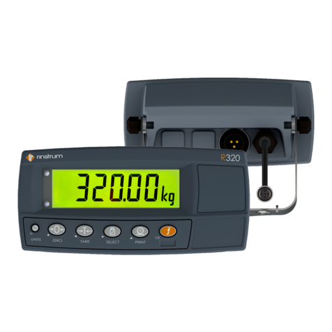
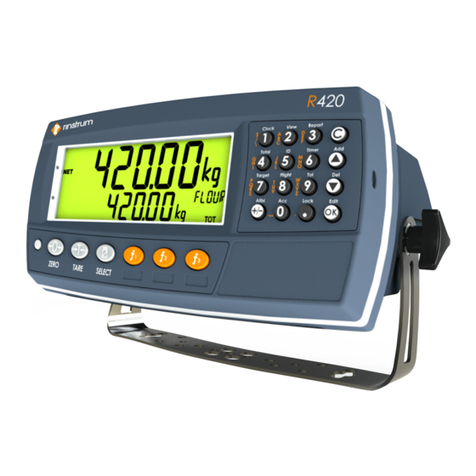
Rinstrum 400 Series Instruction manual

400 Series
(K411)
Batching Indicator
Quick StartManual
004R-615-120

Copyright
All RightsReserved.Nopartofthisdocument maybe
copied,reproduced, republished, uploaded, posted,
transmitted, distributed,stored inor introduced intoa
retrievalsysteminanyform, or byanymeans(electronic,
mechanical,photocopying, recording or otherwise)
whatsoever without prior written permission of Rinstrum
PtyLtd.
Disclaimer
RinstrumPtyLtdreservestheright tomakechangesto
the productscontained inthismanualinorder toimprove
design,
performanceorreliability.
The information inthismanualisbelieved tobe accurate
inall respectsatthetimeof publication, but issubjectto
change without notice.RinstrumPtyLtdassumesno
responsibilityfor anyerrorsoromissionsand disclaims
responsibilityfor anyconsequencesresultingfromtheuse
of theinformation provided herein.

Quick Start - Software Version 1.x & 2.x
004R-615-120 Page 1
Table of Contents
1. INTRODUCTION ........................................................................3
1.1. Manuals ............................................................................3
1.2. Shipping Contents.............................................................3
2. SPECIFICATIONS .....................................................................4
3. INSTALLATION .........................................................................5
3.1. Introduction .......................................................................5
3.2. General Warnings .............................................................5
3.3. Panel Mount Template......................................................6
3.4. Function Keys ...................................................................6
3.5. Optical Communications ...................................................6
4. CONNECTIONS .........................................................................7
4.1. Cable Connections............................................................7
4.2. DC Power (DC PWR +, DC PWR –).................................7
4.3. Load Cell Connection........................................................7
4.4. Auxiliary Connections .......................................................9
4.5. Connecting Shields .........................................................11
4.6. Legal Sealing Details ......................................................12
5. INSTRUMENT SETUP .............................................................15
5.1. Accessing Full/Safe Setup ..............................................15
5.2. Exiting Full or Safe Setup ...............................................16
5.3. Using Menus ...................................................................16
6. SETUP MENUS........................................................................17
6.1. GEN.OPT (General options) ...........................................17
6.2. H.WARE (Hardware Configuration & Test).....................21
6.3. SCALE (Loadcell options and calibration) ......................24
6.4. FUNC (Special functions) ...............................................27
6.5. SER.NET (Network communications).............................32
6.6. SER.AUT (Automatic transmit) .......................................33
6.7. PRINT (Printouts)............................................................34
6.8. SETP (Setpoints) ............................................................36
6.9. BATCH............................................................................38
6.10. ANL.OUT (Analogue Output) ..........................................47
6.11. End (Save and exit) ........................................................47
7. ACCESSORY MODULES........................................................48
7.1. General ...........................................................................48
7.2. Installation and configuration ..........................................48
7.3. Input/Output Configuration..............................................49

Quick Start - Software Version 1.x & 2.x
Page 2 004R-615-120
7.4. Analogue Output .............................................................50
7.5. Communications .............................................................50
8. HARDWARE TESTING............................................................52
8.1. Overview .........................................................................52
8.2. Check Hardware Allocation.............................................52
8.3. Check Inputs ...................................................................53
8.4. Force Outputs .................................................................53
8.5. Force Analogue Output...................................................54
8.6. Check Load Cell Hardware .............................................54
9. ERROR MESSAGES ...............................................................55
9.1. Overview .........................................................................55
9.2. Weighing Errors ..............................................................55
9.3. Setup Errors....................................................................56
9.4. Calibration Errors ............................................................57
9.5. Pause Conditions............................................................58
9.6. Diagnostic Errors ............................................................59

Quick Start - Software Version 1.x & 2.x
004R-615-120 Page 3
1.Introduction
This manual contains information on the installation, calibration
and setup of the indicator.
1.1. Manuals
For more information on the indicator refer to the Reference
Manual and Operator Manual.
1.2. Shipping Contents
The following table identifies the items shipped with indicators.
Please check that your packing box contains the specified
items.
Standard Indicator
•Digital Weighing Indicator
•Operator Manual
•Quick Start Manual
•Trade Label
•Panel Mount Template
•Function Key Overlay Stickers
Other Items (Optional)
There are optional accessories for this indicator, which include:
•Mounting options
•Power supply options
•Expansion modules (which supply additional
communications ports, I/O, analogue output, etc).
•optoLINK temporary connection cable
•PC based configuration tool

Quick Start - Software Version 1.x & 2.x
Page 4 004R-615-120
2. Specifications
Performance
Resolution Up to 100,000 divisions, minimum of 0.25µV/division
Zero Cancellation +/- 2.0mV/V
Span Adjustment 0.1mV/V to 3.0mV/V
Stability/Drift Zero: < 0.15µV/°C (+ 10ppm of deadload max)
Span < 10 ppm/°C, Linearity < 20ppm, Noise < 0.2µVp-p
Excitation 7.4 volts for up to 16 x 350 or 32 x 700 ohm load cells (4-wire or
6-wire plus shield)
Maximum total load cell resistance: 1,000 ohms
A/D Type 24bit Sigma Delta with ±8,388,608 internal counts
Operating
Environment
Temperature: –10 to +50°C ambient
Humidity: <90% non-condensing
Storage: –20 to +50°C ambient
IP65 when panel mounted or with rear boot (otherwise IP40)
Case Materials ABS, Silicon Rubber, Nylon, Acrylic (no halogen used)
Packing Weights Basic Indicator: 0.7kg
Digital
Display LCD with 4 alpha-numeric displays and LED backlighting:
Primary display: 6 x 28.4mm high digits with units and
annunciators
2nd display: 9 x 17.6 mm digits with units
3rd display: 8 x 6.1 mm digits
4th display: 4 x 7.6 mm digits
Setup and Calibration Full digital with visual prompting in plain messages
Digital Filter Sliding window average from 0.1 to 30.0 seconds
Zero Range Adjustable from +/- 2% to +/- 20% of full capacity
Power Input
Standard Power Input 12 to 24VDC (15 VA max) - ON/OFF key with memory feature
Variants
M4101 AC
AC power supply
Input: 110/240VAC 50/60Hz
Output: 12VDC 15VA
M4102 Battery
2.5AH NiMH rechargeable battery pack
Charger Input: 110/240VAC 50/60Hz
Output: 12VDC
Features
Optical Data
Communications
Magnetically coupled optical communications support. Optional
conversion cable connects directly to a standard USB or RS-232
port.
Correction 10 point linearity correction
Serial Outputs RS-232 serial port for remote display, network or printer
supports. RS-485 transmit only for remote display
Transmission rate: 2400, 4800, 9600, 19200 or 57600 baud
3 assignable function
keys
Printing, unit switching, counting, manual hold, peak hold and
totalizing
Battery Backed Clock
Calendar
Battery life 10 years minimum
Approvals FCC, CE, C-tick, Check trade approvals

Quick Start - Software Version 1.x & 2.x
004R-615-120 Page 5
3.Installation
3.1. Introduction
The following steps are required to set up the indicator.
•Inspect indicator to ensure good condition.
•Use connection diagrams to wire up load cell, power and
auxiliary cables as required.
•Use the drilling template provided for hole locations.
•Connect Power to indicator and press <POWER> key to
turn the instrument ON.
•Refer to the Instrument Setup section page 15 for
information on configuring and calibrating the instrument.
•To turn instrument OFF press and hold <POWER> key for
three seconds (until display blanks).
3.2. General Warnings
•Indicator not to be subject to shock, excessive vibration or
extremes of temperature (before or after installation).
•Inputs are protected against electrical interference, but
excessive levels of electro-magnetic radiation and RFI
may affect the accuracy and stability.
•For full EMC or for RFI immunity, termination of cable
shields and correct earthing of the instrument is essential.
•Indicator and load cell cable are sensitive to excessive
electrical noise. Install well clear of any power or switching
circuits.
3.2.1. Electrical Safety
•For your protection all mains electrical hardware must be
rated for environmental conditions of use.
•Pluggable equipment must be installed near an easily
accessible power socket outlet.

Quick Start - Software Version 1.x & 2.x
Page 6 004R-615-120
•To avoid the possibility of electric shock or damage to the
instrument, always switch off or isolate the instrument from
the power supply before maintenance is carried out.
3.3. Panel Mount Template
The panel mount template is supplied with the instrument. It
shows the location of the rectangular cut-out and the four
mounting screws.
3.4. Function Keys
•The indicator has 3 user definable functions keys.
•Special function overlay stickers are supplied. Affix to
matching special function key if used.
•Ensure keypad is clean and dry before affixing sticker.
3.5. Optical Communications
A temporary infrared communications link can be established
between the instrument and a PC using an optional opto-link
cable. This connection can be used to transfer setup and
calibration information from a PC or to download indicator
software upgrades.
The PC end of the cable is a standard female DB9 RS232 or
USB connector. The instrument end of the cable attaches to
the left side of the instrument display.
WARNING
The optical coupling head contains a strong magnet and
should not be placed near any magnetic storage media
(e.g. credit cards, floppy disks etc.)

Quick Start - Software Version 1.x & 2.x
004R-615-120 Page 7
4. Connections
4.1. Cable Connections
All cable connections are made to the rear of the instrument
using pluggable screw terminals. It is not necessary to tin the
ends of the wires with solder or to add crimp ferrules to the
wires, but these techniques are compatible with the terminals.
4.2. DC Power (DC PWR +, DC PWR –)
The DC supply need not be regulated, provided that it is free of
excessive electrical noise and sudden transients. The
instrument can be operated from a high quality plug-pack as
long as there is sufficient capacity to drive both it and the load
cells.
4.3. Load Cell Connection
4.3.1. Load Cell Signals
Very low output scale bases may be used but may induce
some instability in the weight readings when used with higher
resolutions. Generally speaking, the higher the output, or the
lower the number of divisions, the greater the display stability
and accuracy.
The instrument can display the mV/V reading
(H.WARE:LC.HW:MVV) which can be used to check scale
base signal output levels. The instrument may be connected
for either 4-wire or 6–wire operation. Use 4-wire when external
SENSE connections are not available.

Quick Start - Software Version 1.x & 2.x
Page 8 004R-615-120
4.3.2. 4-Wire Connection
The minimum connectivity requirements are the connection of
four wires (i.e. ±Excitation and ±Signal). Internally the
instrument has a precision analogue switch that can be used
to connect the Sense+ and Sense– lines directly to the
Excitation+ and Excitation– lines.
Any addition to the load cell manufacturer's cable length using
4-wire connection is only recommended for short cable runs.
Where long additions to cable lengths are needed, a 6-wire
extension is required.
The SCALE:BUILD:CABLE option must be set to 4-WIRE to
allow for 4-wire connection.

Quick Start - Software Version 1.x & 2.x
004R-615-120 Page 9
4.3.3. 6-Wire Connection
The excitation and signal lines are connected the same as for a
4-wire installation. The extra two wires (Sense + and –) should
be connected to the Excitation + and – lines as close as
possible to the load cell itself. Typically these connections are
made in a load cell termination box.
The BUILD:CABLE option must be set to 6-WIRE to allow for
true 6-wire connection.
4.4. Auxiliary Connections
This section provides diagrams to illustrate the communication
connections.
4.4.1. Direct Personal Computer Link (RX, TX GND)

Quick Start - Software Version 1.x & 2.x
Page 10 004R-615-120
4.4.2. Printer Connections (RXD/TXD, GND and DTR)
4.4.3. Remote Display using RS232 (TXD, GND)
Refer to documentation supplied with the Remote Display for
connection details. Connect RX on the Remote Display with
TX on the instrument and connect the RS232 GND signals
together.
4.4.4. Remote Display using RS485 (TA, TB)
RS485 is recommended for communicating over distances
longer than a few metres. Refer to documentation supplied
with the Remote Display for connection details. Connect TA to
RA and TB to RB.

Quick Start - Software Version 1.x & 2.x
004R-615-120 Page 11
4.5. Connecting Shields
To obtain full EMC or for RFI immunity, cable shields
MUST be connected and the earth lug on the rear of the
instrument must be grounded.
This figure illustrates an example of possible connections. Also
shown are the connecting cables restrained using cable ties
fastened by screws into the rear of the unit.

Quick Start - Software Version 1.x & 2.x
Page 12 004R-615-120
4.5.1. Cable Shield Connection and Earthing
•Care should be taken when connecting shields to maximise
EMC or RFI immunity and minimise earth loops and cross-talk
(interference) between instruments.
•For full EMC or for RFI immunity, termination of the cable
shields at the earth lug is very important. The earth lug of the
instrument must be separately connected to ground potential
via a reliable link.
•The AC power module directly connects the earth lug to the
Earth Pin on the power supply. In installations where earth is
available on the power cable, instrument earthing can be done
with this connection.
•The instrument should only be connected to earth via a single
reliable link to avoid earth loops.
•Where each instrument is separately earthed, interconnecting
cable shields should be connected at one end only.
•Caution: Some load cells connect the cable shield directly to
the load cell (and therefore the scale base). Connection of the
load cell cable shield may be site specific.
4.6. Legal Sealing Details
There are several methods of legally sealing the instrument.
The method chosen will depend on local regulations.
4.6.1. Trade Label and Electronic Seal
For trade-certified applications, a tamperproof certification label
can be placed on the front of the instrument to provide an
electronic seal. The instrument has a built-in calibration
counter to monitor when
critical settings are altered.
The value of the calibration
counter should be written on
the certification label.

Quick Start - Software Version 1.x & 2.x
004R-615-120 Page 13
4.6.2. Lead Seals
There are 2 methods of sealing the instrument with lead and
wire seals:
Figure 1: Lead seal on rear of instrument.
Figure 2: Lead seal on boot.

Quick Start - Software Version 1.x & 2.x
Page 14 004R-615-120
4.6.3. Destructible Sticker Seals
There are 2 methods of sealing with destructible stickers:
Figure 3: Destructible sticker seal on rear of instrument.
Figure 4: Destructible sticker seal on boot.

Quick Start - Software Version 1.x & 2.x
004R-615-120 Page 15
5.Instrument Setup
5.1. Accessing Full/Safe Setup
When Full Setup is used, all menu items are accessible,
including legal for trade and calibration sensitive settings, and
care must be taken to ensure no accidental changes are made
to calibration and trade settings. The Safe Setup method
restricts access to the Trade Critical settings.
WARNING
All items in all menus will be enabled in Full Setup. Care
should be taken to avoid inadvertently altering the Build or
Calibration settings.
Full Setup
To access Full Setup, first ensure the
instrument is on. Then press and hold both
the <POWER> and <F3> keys together for
two seconds.
Safe Setup
To access Safe Setup, first ensure the
instrument is on. Then press and hold both
the <POWER> and <ZERO> keys together for
two seconds.
Full and Safe Setup can be passcode protected to prevent
unauthorised or accidental tampering. If the passcode is lost,
the manufacturer should be contacted for further advice.

Quick Start - Software Version 1.x & 2.x
Page 16 004R-615-120
5.2. Exiting Full or Safe Setup
To save settings, exit setup and return to the normal
weighing mode using one of the following methods:
Method 1: Press the <POWER> key.
Method 2: Press the <ZERO> key repeatedly. When
END displays press <TARE>.
If the power is interrupted while in setup (i.e. by disconnecting
the power cable), unsaved settings will be lost.
5.3. Using Menus
R
Level 1 Level 2 Level 3 Level 4 Level 5
Example: GEN.OPT
└PCODE
└SAFE.PC

Quick Start - Software Version 1.x & 2.x
004R-615-120 Page 17
6. Setup Menus
6.1. GEN.OPT (General options)
DATE.F (Date format)
Path Description
GEN.OPT
└DATE.F
DATE.F Values <OPT>
DD.MM.YYYY (Default) ,
DD.MM.YYYY,
MM.DD.YY
MM.DD.YYYY,
YY.MM.DD,
YYYY.MM.DD
Sets the date format
PCODE (Security passcodes)
Path Description
GEN.OPT
└PCODE
└SAFE.PC
└FULL.PC (*)
└OP.PC
(*) Available in FULL SETUP only
PCODE Values <NUM>
0 (Default) .. 999999
Note: A passcode value
of 0 deactivates the
passcode.
Sets the instrument passcodes. The three
levels of passcode are:
Full passcode (FULL.PC): Controls access
to full setup menus. All settings (including
trade critical settings) can be altered from
full setup. The full passcode will also give
access to safe or operator functions.
Safe passcode (SAFE.PC): Controls
access to safe setup menus. No trade
critical settings can be altered from safe
setup. The safe passcode also gives
access to operator functions as defined by
Key Lock.
Operator passcode (OP.PC): Controls
access to operator functions, as defined by
Key Lock.

Quick Start - Software Version 1.x & 2.x
Page 18 004R-615-120
KEY.LOC (Key Function Access Control)
Path Description
GEN.OPT
└KEY.LOC
└P(*)
└ZERO
└TARE
└RECIPE
└F1
└F2
└F3
└CLOCK
└VIEW
└REPORT
└TOTAL
└ID
└TARGET
└ACC
└PR.MOD
└PR.SEL
└NUM.PAD
└ALIBI
└RECIPE
└FLIGHT
└TOL
└TIMERS
KEY.LOC Values <OPT>
AVAIL*,OPER.PC,
SAFE.PC, LOCKED*
(*) only are available for
POWER.
Access to each of the operator functions can
be configured separately as either:
AVAIL: function always available
OPER.PC: requires a valid Operator
Passcode
SAFE.PC: requires a valid Safe Passcode
LOCKED: function never available
Functions protected with a ‘Safe’ passcode
prompt for the passcode every time.
Entering the Operator Passcode unlocks all
operator protected functions so the operator
is not continually prompted for the
passcode. In order to lock the instrument
again press the ‘.’ key for two seconds
(function ‘Lock’).
Other manuals for 400 Series
7
This manual suits for next models
1
Table of contents
Other Rinstrum Measuring Instrument manuals

Rinstrum
Rinstrum 2100 Instruction manual
Rinstrum
Rinstrum 400 Series User manual

Rinstrum
Rinstrum 400 Series User manual

Rinstrum
Rinstrum 5200 Use and care manual

Rinstrum
Rinstrum M4202 User manual

Rinstrum
Rinstrum K405 User manual

Rinstrum
Rinstrum 400 Series User manual

Rinstrum
Rinstrum R300 Series User manual
Rinstrum
Rinstrum C300 Series User manual

Rinstrum
Rinstrum 400 Series User manual