Rinstrum 5200 Use and care manual

5200
(Totaliser/Checkweigher)
Digital Indicato
r
Communications
Manual
For use with Software Versions 1.0 and above
0025-605-120

Rinstrum - 5200 Communications Manual Rev 1.2
Page 2 0025-605-120
Copyright
All Rights Reserved. No part of this document may be copied, reproduced, republished,
uploaded, posted, transmitted, distributed, stored in or introduced into a retrieval system in
any form, or by any means (electronic, mechanical, photocopying, recording or otherwise)
whatsoever without prior written permission of Rinstrum Pty Ltd.
Disclaimer
Rinstrum Pty Ltd reserves the right to make changes to the products
contained in this manual in order to improve design, performance or reliability.
The information in this manual is believed to be accurate in all respects at the time of
publication, but is subject to change without notice. Rinstrum Pty Ltd assumes no
responsibility for any errors or omissions and disclaims responsibility for any
consequences resulting from the use of the information provided herein.
SPECIAL NOTE
Trade Use of the Rinstrum 5200
This manual may occasionally make reference to Trade Use settings of the 5200. Only
properly marked Trade Certified versions of the 5200 can be used in Legal for Trade
applications. Trade Certification is available only on 5200 instruments with software
Versions 1.0 and above.
Some individual settings may not be legal for trade use. Please check regulations with the
appropriate Weights and Measures Authority.
“Everything should be made as simple as possible, but not simpler.”
- Albert Einstein -

Rinstrum - 5200 Communications Manual Rev 1.2
0025-605-120 Page 3
Table of Contents
1. INTRODUCTION....................................................................................................... 5
1.1. Audience......................................................................................................... 5
1.2. Scope.............................................................................................................. 5
1.3. Manuals .......................................................................................................... 5
1.4. Document Conventions................................................................................... 5
2. CONNECTION OF THE 5200 NETWORK................................................................ 6
2.1. RS-232 Connection......................................................................................... 6
2.2. RS-485 Connection......................................................................................... 7
2.3. Overview......................................................................................................... 8
2.3.1. Commands and Queries .................................................................. 8
2.3.2. Responses ....................................................................................... 8
2.3.3. Parameters ...................................................................................... 8
2.3.4. Termination ...................................................................................... 9
2.3.5. Trade Counter.................................................................................. 9
2.4. Command Details ......................................................................................... 10
2.4.1. ACL: Set Automatic Temperature Calibration On/Off..................... 10
2.4.2. ADR: Set Address.......................................................................... 11
2.4.3. ASF: Set Filtering........................................................................... 12
2.4.4. BDR: Set Baud Rate ...................................................................... 13
2.4.5. CDL: Set Zero ................................................................................ 14
2.4.6. CHK: Set Checkweigh (Catchweigh) Options ................................ 15
2.4.7. CLK: Set Clock............................................................................... 16
2.4.8. COF: Set Output Format ................................................................ 17
2.4.9. CWT: Set Calibration Weight ......................................................... 19
2.4.10. DSP: Set Display Options .............................................................. 20
2.4.11. DTF: Set time and date format....................................................... 21
2.4.12. ENU: Set Units............................................................................... 22
2.4.13. ESR: Query Error Status................................................................ 23
2.4.14. FCN: Function Key Setting............................................................. 25
2.4.15. FOP: Force Output......................................................................... 26
2.4.16. IAD: Set Scale Build....................................................................... 27
2.4.17. ICR: Set Measurement Rate .......................................................... 28
2.4.18. IDN: Set Identification .................................................................... 29
2.4.19. LBT: Button lock settings ............................................................... 30
2.4.20. LDW: Calibrate Zero Dead Weight................................................. 31
2.4.21. LIC: Linearisation ........................................................................... 32
2.4.22. LIV: Set Limit Value........................................................................ 33
2.4.23. LWT: Calibrate Span...................................................................... 34
2.4.24. MSV?: Query Measured Weight Value .......................................... 35
2.4.25. MTD: Motion Setting ...................................................................... 36
2.4.26. PCD: Motion Setting....................................................................... 37
2.4.27. PEV: Custom Print Events ............................................................. 38
2.4.28. PRD: Product Information .............................................................. 39
2.4.29. PRS: Printer Settings ..................................................................... 41
2.4.30. PRT: Print ...................................................................................... 42
2.4.31. PST: Print strings ........................................................................... 43
2.4.32. RBT: Remote Button Settings ........................................................ 44
2.4.33. RES: Reset .................................................................................... 45
2.4.34. SER: Set Serial Communications Settings..................................... 46
2.4.35. STP: Stop Continuous Transfer ..................................................... 47
2.4.36. Sxx: Select Instrument ................................................................... 48
2.4.37. TAR: Tare ...................................................................................... 49
2.4.38. TAS: Gross/Net.............................................................................. 50
Rinstrum - 5200 Communications Manual Rev 1.2
Page 4 0025-605-120
2.4.39. TAV: Set Tare Value ...................................................................... 51
2.4.40. TDD: Load/Save Setup .................................................................. 52
2.4.41. VAL?: mV/V Value Query............................................................... 53
2.4.42. WMD: Set Weighing Mode............................................................. 54
2.4.43. ZST: Zero Settings ......................................................................... 55
3. COMMAND SUMMARY.......................................................................................... 56
3.1. Set Communication Parameters ................................................................... 56
3.2. Set Scale Build ............................................................................................. 56
3.3. Calibration..................................................................................................... 56
3.4. Set Scale Options ......................................................................................... 56
3.5. Product Totalising and Checkweighing Settings ........................................... 56
3.6. General Commands...................................................................................... 57
3.7. Queries ......................................................................................................... 57
3.8. Test Commands ........................................................................................... 57
3.9. Common Commands.................................................................................... 57

Rinstrum - 5200 Communications Manual Rev 1.2
0025-605-120 Page 5
1. Introduction
This manual details the extended networking capabilities (communications protocol) of the
5200.
The extended protocol allows for complete calibration and control of a multi-drop network
of up to 32 5200 instruments. This protocol is used by the View5200 program to calibrate
and configure the 5200 instruments. The Viewer TEST tab can be used as a convenient
terminal to test the 5200 communications.
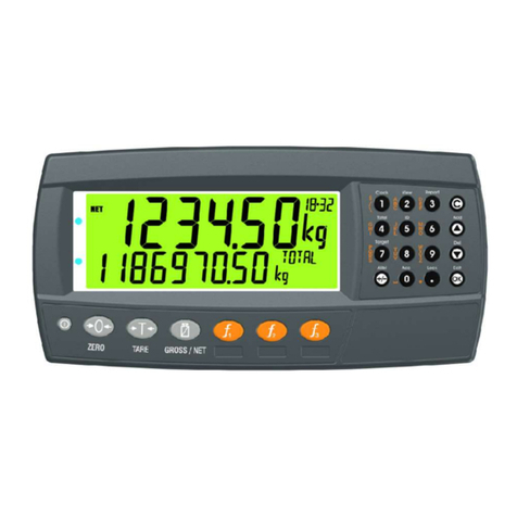
Figure 1: Rinstrum 5200 Digital Indicator
1.1. Audience
This manual is aimed at the designer or installer who is familiar with the operation
and setup of the 5200 Totaliser/Checkweigher (Catchweigher).
1.2. Scope
This manual lists all of the commands for the extended protocol in alphabetical
order. In practice only a small subset of these commands would be used to control
operational parameters. The Command Summary on page 56 groups the
commands into related functions.
1.3. Manuals
For more information on the 5200 Totaliser/Checkweigher, refer to the 5200
Reference Manual, 5200 Operator Manual, 5200 Quick Start Manual or the 5200
Applications Manual (available from www.rinstrum.com).
1.4. Document Conventions
The following document conventions are used throughout this manual.
Bold Text Bold text denotes words and phrases to note.
^ This symbol denotes one space (used in 5200 Commands)
… Ellipses indicate an incomplete listing. For space considerations in
this Manual complete listings of returned Command responses may
not be shown.

Rinstrum - 5200 Communications Manual Rev 1.2
Page 6 0025-605-120
2. Connection of the 5200 Network
2.1. RS-232 Connection
Figure 2: RS-232 Network Connection - 5200 to PC Using COM1
Figure 3: RS-232 Network Connection - 5200 to PC Using COM2

Rinstrum - 5200 Communications Manual Rev 1.2
0025-605-120 Page 7
2.2. RS-485 Connection
Figure 4: Multi-Drop Networking Connections - Connecting to First
Instrument
Figure 5: Multi-Drop Networking Connections - Connecting to Next
Instrument

Rinstrum - 5200 Communications Manual Rev 1.2
Page 8 0025-605-120
2.3. Overview
2.3.1. Commands and Queries
• A Command consists of three ASCII characters (eg. IDN).
• A Query consists of four ASCII characters (the last character being a question
mark) (eg. IDN?).
Before a command or query can be sent, the instrument, which should execute that
command, must be selected. Refer to Sxx: Select Instrument page 48 for more
information.
2.3.2. Responses
The 5200 will return one of the following responses:
Response Description
0 Indicates that a command has been accepted.
1 Indicates that a command failed due to motion.
2 Indicates that a command failed due to an out-of-range condition.
3 Indicates that a command failed due to system errors.
? Indicates that the command was either not understood or could
not be performed.
Specific queries cause the 5200 to respond with the data requested by the query.
For example, if the 5200 was setup with address 4 it would respond with 04 to the
ADR? query.
2.3.3. Parameters
The following rules apply to parameters:
• A command or query can be followed by one or more parameters.
• Parameters are either numeric (eg. 3000) or strings (eg. "Fred").
• String parameters are delimited by quote characters ( "ASCII 34). They are
taken literally (ie. "AbCd" is not the same as "abcd").
• Numeric parameters are variable and leading and trailing spaces are ignored
(ie. 003, 03 and 3 are identical).
• Parameters are separated by the comma character ( ,ASCII 44).
• Most parameters may be left out completely. This makes it possible to change
one parameter without altering the others. For example IAD1,,2; would change
only the position of the decimal place.

Rinstrum - 5200 Communications Manual Rev 1.2
0025-605-120 Page 9
2.3.4. Termination
Termination characters are sent to define the end of a command, query or
response. The following are permissible termination characters:
Termination Character ASCII Code(s)
; 59
LF 10
CRLF 13 10
LFCR 10 13
For example, ADR?; is the same as ADR? CRLF.
Note: The 5200 invariably uses CRLF as the termination of its responses.
2.3.5. Trade Counter
All trade relevant functions are guarded by the trade counter. There is no difference
in changing settings via the communications interface or via the front panel. If the
counter reaches 60000 the 5200 operation is blocked and it must be returned to the
factory.
Note that the 5200 does not check to see if the new data is different from the old
data before incrementing the Trade Counter, so sending IAD1,6000 will increment
the counter even if the 5200 is already setup with a fullscale of 6000 kg.
It is possible to block all changes to trade relevant parameters by setting a Full
Setup Passcode. If such a passcode has been set, trade parameters can only be
changed via the serial port after a PCD command has been sent with the correct
passcode.

Rinstrum - 5200 Communications Manual Rev 1.2
Page 10 0025-605-120
2.4. Command Details
2.4.1. ACL: Set Automatic Temperature Calibration On/Off
This is used to set the Automatic Temperature Calibration On/Off.
General Details
No. of Parameters Save Changes Changes Used Increment Trade Counter
2 - - - - - - Immediately No
Parameter Details
Parameter Description Range Default Required
1 Temperature
calibration during no
motion
0 to 1 (0: Off, 1: On) 1 No
2 Temperature
calibration during
motion
0 to 1 (0: Off, 1: On) 1 No
The 5200 performs an automatic temperature calibration to ensure that changes in
ambient temperature do not affect accuracy. During this calibration no new data is
received. The time taken for this calibration depends on the sync frequency
according to the following formula: 6 / sync frequency (seconds).
This feature cannot be used in Trade mode and both parameters are set to ON
when the instrument is reset.

Rinstrum - 5200 Communications Manual Rev 1.2
0025-605-120 Page 11
2.4.2. ADR: Set Address
This is used to set the address of an instrument.
General Details
No. of Parameters Save Changes Changes Used Increment Trade Counter
2 With TDD1 Immediately No
Parameter Details
Parameter Description Range Default Required
1 Address 0 to 31 31 No
2 Serial Number 0000001 to
9999999
Factory Set No - Command Only
Each 5200 must be assigned a unique address to enable the implementation of a
multi-drop network. The ADR command is used to assign the instrument address
via the communications network.
The following procedure can be used if a 5200 (with a known serial number) and an
unknown (or not unique) address is attached to a multi-drop network.
• Select all instruments using the S99 command.
• Send the ADR command with the new address and the serial number of the
chosen instrument. The ADR command will execute only for the instrument with
the correct serial number. Note: The serial number parameter is used
exclusively for this task.
• Continue until all instruments have unique addresses.
If the serial number is not known, the instruments must be turned on one at a time.
The combination of the S99 and ADR commands can be used to set the addresses.
Example 1: Change Address of Instrument from 1 to 2
Command Response Details
S01; Select Instrument 1
ADR2; 0 CRLF Set Address to 2
TDD1; 0 CRLF Save Change
S02; Select New Instrument
2
IDN?; " ","01234567","5200",0 CRLF Ask for ID
Example 2: Two Instruments (Unknown Addresses) Configured Using Serial
Numbers
Command Response Details
S99; Select All Instruments
ADR01, "123456"; 0 CRLF Instrument With Serial No.
"123456" Gets Address 01
ADR02, "123457"; 0 CRLF Instrument With Serial No.
"123457" Gets Address 02
S01;TDD1;
S02;TDD1;
0 CRLF Save Address Against Power
Loss
S01; Select New Instrument 1
IDN?; " ","0123456","V1.0","5200"
,0 CRLF
Ask for ID

Rinstrum - 5200 Communications Manual Rev 1.2
Page 12 0025-605-120
2.4.3. ASF: Set Filtering
This is used to set the filtering characteristics of an instrument.
General Details
No. of Parameters Save Changes Changes Used Increment Trade Counter
2 With TDD1 On TDD1 No
Parameter Details
Parameter Description Range Default Required
1 Number of
consecutive
readings to
average
0
…
9
10
11
12
13
14
1
…
10
25
50
75
100
200
9 No
2 Anti-Jitter
Setting
0
1
2
Off
Fine
Course
0 No
Example
Command Response Details
S01; Select Instrument 1
ASF?; 10,00,00 CRLF Query Filtering Setting
ASF4,1; 0 CRLF Changed to a 5 reading average with fine
anti-jitter filtering
TDD1; 0 CRLF Save New Settings

Rinstrum - 5200 Communications Manual Rev 1.2
0025-605-120 Page 13
2.4.4. BDR: Set Baud Rate
This is used to set the communication parameters, baud rate, parity, etc.
General Details
No. of Parameters Save Changes Changes Used Increment Trade Counter
8 With TDD1 Immediately No
Parameter Details
Parameter Description Range Default Required
1 Port 0
1
Serial 1
Serial 2
- Yes
2 Baud Rate 0
1
2
3
4
5
6
300
600
1200
2400
4800
9600
19200
5 No
3 Parity 0
1
2
None
Odd
Even
0 No
4 Data bits 7,8 8 No
5 Stop bits 1,2 1 No
6 Termination
Resistors
0
1
OFF
ON
0 No
7 RS-232/
RS-485
(Serial 1 only)
0
1
RS-485
RS-232
0 No
8 CTS
(Serial 2 only)
0
1
OFF
ON
0
No
Example
Change baud rate of instrument 1 serial 1.
Command Response Details
S01; Select Instrument 1
BDR?0; 0,5,0,8,1,0,0,0 CRLF Query Baud Rate Setting
BDR0,3; 0 CRLF
Note: Reply is sent using the new
settings if using the changed port.
Settings changed to 2400 baud
TDD1; 0 CRLF Save New Settings

Rinstrum - 5200 Communications Manual Rev 1.2
Page 14 0025-605-120
2.4.5. CDL: Set Zero
Set the zero dead load cancellation. This is equivalent with pressing the <ZERO>
key on the front of the instrument.
General Details
No. of Parameters Save Changes Changes Used Increment Trade Counter
0 Automatic Immediately No
Example
Set Zero.
Command Response Details
S01; Select Instrument 1
CDL; 0 CRLF Zero dead load set successfully
CDL; 2 CRLF Failed due to weight out of zero range

Rinstrum - 5200 Communications Manual Rev 1.2
0025-605-120 Page 15
2.4.6. CHK: Set Checkweigh (Catchweigh) Options
Set the checkweigh options.
General Details
No. of Parameters Save Changes Changes Used Increment Trade Counter
12 With TDD1 Immediately No
Parameter Details
Parameter Description Range Default Required
1 Trigger Option 0
1
Input trigger only
Weight and/or input
trigger
- No
2 Weight Trigger
Level
999999 to –999999 100 No
3 Weight Trigger
Reset Level
999999 to –999999 0 No
4 Pre-average
Delay
0 to 30000 (x0.01s) 100 No
5 Average time 0 to 30000 (x0.01s) 100 No
6 Display Option 0
1
2
Normal weight
display
Check weight display
Check grade display
0 No
7 Display Timeout 0 to 30000 (x0.01s) 300 No
8 to 12 No Grade
Name,
Grade 1 Name
to Grade 4
Name
6 character string “G0” to
“G4”
No
Example
Set trigger option to weight trigger.
Command Response Details
S01; Select Instrument 1
CHK?; 0,100,0,100,100,0,300,"G0","G1",
"G2","G3","G4" CRLF
Query checkweigh settings
CHK1; 0 CRLF Trigger changed to weight
TDD1; 0 CRLF Save New Settings

Rinstrum - 5200 Communications Manual Rev 1.2
Page 16 0025-605-120
2.4.7. CLK: Set Clock
Set the time and date.
General Details
No. of Parameters Save Changes Changes Used Increment Trade Counter
6 Automatic Immediately No
Parameter Details
Parameter Description Range Default Required
1 Hour 0 to 23 - No
2 Minute 0 to 59 - No
3 Second 0 to 59 - No
4 Date 1 to 31 - No
5 Month 1 to 12 - No
6 Year 0 to 99 (or 2000 to 2099) - No
The year may be in 2 digit or 4 digit format. The 5200 will always respond to queries
in 2 digit format.
Example
Command Response Details
S01; Select Instrument 1
CLK?; 5,5,55,22,4,0 CRLF Query date and time
CLK15,40,0,5,2,2003; 0 CRLF Change to 3:40pm 5/2/2003
CLK15,40,0,5,2,3; 0 CRLF Same as above

Rinstrum - 5200 Communications Manual Rev 1.2
0025-605-120 Page 17
2.4.8. COF: Set Output Format
This is used to set the default output format and reading of the MSV? query. It also
sets the format for the automatic serial outputs.
General Details
No. of Parameters Save Changes Changes Used Increment Trade Counter
1 With TDD1 Immediately No
Parameter Details
Parameter Description Range Default Required
1 Format Setting 0 to 11 6 No
Binary Formats
Format Data Order
0 4 Byte (binary) CRLF MSB before LSB(=00H)
2 2 Byte (binary) CRLF MSB, LSB
4 4 Byte (binary) CRLF LSB(=00H) before MSB
6 2 Byte (binary) CRLF LSB, MSB
8 4 Byte (binary) CRLF MSB before LSB(=Status)
ASCII Formats
Format Parameter 1 Parameter 2 Parameter 3
1, 3 Weight (8) CRLF
5, 7 Weight (8) , Address(2) CRLF
9, 10 Weight (8) , Address(2) , Status (3) CRLF
11 Weight (8) , Address(2) , Extended Status (3) CRLF
Values in brackets signify the number of characters in the fixed length response.
The weight format is the sign (space or minus), followed by 7 digits 0 to 9 including
the decimal point if used.
The binary formats are useful for PLC communications in applications where
conversion of the ASCII weight string is not possible. The binary outputs can
generally be used directly by the PLC.
Status Details
Status Description Bit Comment
001 Overload 0 Weight reading out of range. Underload or
overload.
002 Standstill 1
004 Gross 2
008 Range 2 Active 3 Only used with multi-range or multi-interval.
016 Output 1 Active 4
032 Output 2 Active 5
064 Output 3 Active 6
128 Output 4 Active 7
256 Centre of Zero 8 This status bit is only available in the
extended status - Format 11 only.

Rinstrum - 5200 Communications Manual Rev 1.2
Page 18 0025-605-120
Note: The status bits are added together. For example, a status of 6 (4+2) means
the weight reading is gross, not within centre of zero, there is no motion and all limit
values are inactive.
Example 1: General Use
Command Response Details
S01; Select Instrument 1
COF?; 3 CRLF Query Format
MSV?; –00001.0 CRLF Query Weight Reading
COF9; 0 CRLF Change to Format 9
TDD1; 0 CRLF Save New Setting
MSV?; –00001.0,01,006 CRLF Query weight reading using the new
format
Example 2: Use of Binary Format for PLC Use
Command Response Details
Initialisation
S01; Select Instrument 1
COF8; 0 CRLF Set Format 8
TDD1; 0 CRLF Save Format Setting
PLC Operation
MSV?; Query weight reading using the new format. In
this example the weight is a stable gross reading
of 1000kg.
COF 8 replies with:
<24 bits of weight><8 bit status> CRLF
The hexadecimal values of the returned data are
<00><03><E8><06><0C><0A> but this data is
not printable directly.

Rinstrum - 5200 Communications Manual Rev 1.2
0025-605-120 Page 19
2.4.9. CWT: Set Calibration Weight
Set the calibration weight to be used for span calibration. This must be set before
using the LWT; span calibration command.
General Details
No. of Parameters Save Changes Changes Used Increment Trade Counter
1 With TDD1 Immediately No
Parameter Details
Parameter Description Range Default Required
1 Calibration
Weight
2% - 100% of fullscale
weight.
(Send IAD? to read
fullscale setting)
3000 No
Example
Command Response Details
S01; Select Instrument 1
CWT?; 3000 CRLF Query calibration weight setting
CWT4000; 0 CRLF
(Note that weight is sent without
any decimal point. So 400.0 kg
is send as 4000 not 400.0)
Change Calibration Weight to 4000
TDD1; 0 CRLF Save new setting

Rinstrum - 5200 Communications Manual Rev 1.2
Page 20 0025-605-120
2.4.10. DSP: Set Display Options
Set the backlight and auxiliary display operation.
General Details
No. of Parameters Save Changes Changes Used Increment Trade Counter
2 With TDD1 Immediately No
Parameter Details
Parameter Description Range Default Required
1 Backlight 0
1
OFF
ON
1 No
2 Auxiliary Display 0
1
OFF
TIME
0 No
Example
Command Response Details
S01; Select Instrument 1
DSP?; 1,0 CRLF Query display options
DSP0; 0 CRLF Switch backlight off
TDD1; 0 CRLF Save new setting
Other manuals for 5200
1
Table of contents
Other Rinstrum Measuring Instrument manuals

Rinstrum
Rinstrum 400 Series Instruction manual

Rinstrum
Rinstrum R300 Series User manual

Rinstrum
Rinstrum C300 Series User manual

Rinstrum
Rinstrum 32 Series Instruction manual

Rinstrum
Rinstrum 5200 Instruction manual

Rinstrum
Rinstrum 400 Series User manual

Rinstrum
Rinstrum R300 Series Instruction manual

Rinstrum
Rinstrum M4201 User manual

Rinstrum
Rinstrum K405 User manual

Rinstrum
Rinstrum 2100 Instruction manual