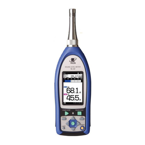
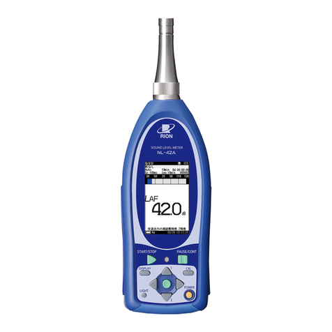
Rion NA-28 User manual

3-20-41 Higashimotomachi, Kokubunji, Tokyo 185-8533, Japan
http://www.rion.co.jp/english/
SERIAL INTERFACE MANUAL
Sound Level Meter
NA-28


i
Organization of the NA-28 Documentation
The documentation for the Sound Level Meter NA-28 consists of three sepa-
rate manuals.
• Instruction Manual
Describes operating procedures for the Sound Level Meter NA-28,
connection and use of peripheral equipment such as a level recorder
and printer, and use of the memory card.
• Serial Interface Manual (this document)
Describes communication with a computer, using the serial interface
built into the Sound Level Meter NA-28. The manual covers the com-
munication protocol, use of control commands for the sound level meter,
format of data output by the sound level meter, and other topics.
• Technical Notes
This document provides in-depth information about sound level meter
performance, microphone construction and characteristics, inuence
of extension cables and windscreen on the measurement, and other
topics.

ii

iii
Organization of This Manual
This manual describes the features of the serial interface built into the Sound
Level Meter NA-28.
The manual contains the following three sections.
Chapter 1 Preparations for USB Communication
Describes how to connect the unit to a computer via a USB link and how
to install the USB driver. The chapter also contains general information
about usage.
Chapter 2 Basic Syntax
Explains USB related syntax and other items.
Chapter 3 Command Reference
Describes the commands for controlling the NA-28, including command
format, functions, and other aspects.
* All company names and product names mentioned in this manual are
trademarks or registered trademarks of their respective owners.

iv
Contents
Organization of the NA-28 Documentation ..................................... i
Organization of This Manual ........................................................ iii
Chapter 1 Preparations for USB Communication .......................1
About USB Functionality ...............................................................2
Connection to a Computer ..............................................................3
Operating Environment...................................................................4
Installing the USB Driver................................................................5
Installation procedure ...............................................................5
Connection to the computer ....................................................10
Disconnection from the computer ...........................................11
Checking the virtual COM port ..............................................12
Chapter 2 Basic Syntax ............................................................15
Outline .........................................................................................16
Local Mode/Remote Mode ..........................................................17
Transfer Codes ..............................................................................18
Transfer Format.............................................................................19
ID: ID Number .......................................................................20
ATTR: Block Attribute ...........................................................21
Block Reception Processing ..........................................................22
Command Types .....................................................................22
Error Processing .....................................................................23
Transfer Types ........................................................................24
Communication Cutoff..................................................................29
Power Save Mode ...................................................................29
Power Off ...............................................................................29
Auto Shutdown .......................................................................29
Rated Values .................................................................................30

v
Chapter 3 Command Reference ............................................... 31
Commands ...................................................................................32
Command List ........................................................................32
Command Format ...................................................................38
Error Codes ............................................................................39
Parameters ..............................................................................39
Command Send Example ........................................................40
Command Description ............................................................ 41
Examples for Control Via External Commands ......................86

vi

1
Contents
About USB Functionality ................................................................2
Connection to a Computer...............................................................3
Operating Environment...................................................................4
Installing the USB Driver................................................................5
Installation procedure ................................................................5
Connection to the computer .....................................................10
Disconnection from the computer ............................................ 11
Checking the virtual COM port ...............................................12
Chapter 1
Preparations for USB Communication

2
About USB Functionality
The NA-28 supports operation control and data transfer via a USB connection. Con-
nection of multiple units is not supported.

3
Connection to a Computer
The illustration below shows how to connect the USB port on the bottom of the
Sound Level Meter NA-28 to the computer, using a generic USB cable. The USB
cable is an optional.
DC 5-6V
TRIG IN/
COMP OUT
AC DC
OUTPUT USB
USB port
Open cover on bottom
To USB port of computer
USB (mini-B) male
USB (A) male

4
Operating Environment
Supported Operating Systems
- Microsoft Windows XP Professional (32 bit)
- Microsoft Windows 7 Professional (32 bit/64 bit)
- Microsoft Windows 8 Pro (32 bit/64 bit)

5
Installing the USB Driver
By connecting the NA-28 to a computer with a USB cable, and using a dedi-
cated communication/control program, the NA-28 can be controlled remotely
from the computer, and measurement data can be sent to the computer in
real time. To enable use of these functions, you must rst download driver
software from the RION Corporation web site and install this driver on the
computer to be used with the NA-28. The driver will create a virtual COM
port on the computer.
Installation procedure
When connecting the NA-28 and the computer for the rst time, install the
USB driver as follows.
1. Download the latest USB driver from the RION Co., LTD. web site
(http://www.rion.co.jp/english/).
When using 32 bit OS, execute the le “setup.exe” located in the
“installer_x86” folder.
When using 64 bit OS, execute the le “setup.exe” located in the
“installer_x64” folder.
The installation starts.

6
Installing the USB Driver
Follow the wizard to complete the installation.
Screens during installation are as follows.

7
Installing the USB Driver
2. Turn power to the NA-28 on, select [I/O](Input/Output) and set [USB
Communication] to “ON”.
Important
The above steps must be completed before
connecting the USB cable.
3. Connect the NA-28 to the computer with a USB cable.
Important
Connect the NA-28 directly with the USB cable
to the computer. If the NA-28 is connected via a
USB hub, normal operation is not assured.
Depending on your environment, [Windows Security] may be dis-
played. Click on “Install” or “Continue”.

8
Installing the USB Driver
Select “Install the software automatically (Recommended)”, and click on
“Next>”.
In case of Windows XP
When the computer detects the NA-28, [Found New Hardware Wizard] is
started up. Proceed following the wizard.
Select “No, not this time”, and click on “Next>”.
In case of Windows 7 and Windows 8
When the computer detects the NA-28, the device driver software installa-
tion is started automatically. When the installation has been completed, USB
communication is enabled.

9
Installing the USB Driver
Click on “Finish”.
The driver installation creates a virtual COM port in the computer. For infor-
mation on how to verify that the installation was successful, see the section
“Checking the virtual COM port” on page 12.
Click on “Continue Anyway”.

10
Installing the USB Driver
Connection to the computer
If you are connecting the NA-28 to the computer for the rst time, refer to
page 3.
1. Turn power to the NA-28 on, select [I/O] (Input/Output) and set [USB
communication] to “ON”.
2. Connect the NA-28 to the computer with a USB cable.
Important
Be sure to set [USB communication] to “ON” at
the NA-28 before connecting the USB cable.
USB communication is now enabled.

11
Installing the USB Driver
Disconnection from the computer
CF card in NA-28 will be recognized as “removable media”. Consequently,
the correct procedure as described below must be followed when discon-
necting the unit.
1. Click on the “Safely remove hardware” icon in the right section of
the taskbar, and select “Safely remove USB Mass Storage Device
- Drive (*1)”.
*1: The drive letter (E in the example shown) will differ, depending
on the computer conguration.
2. When the message shown below appears, disconnect the USB
cable.
The NA-28 is now properly disconnected.

12
Installing the USB Driver
Checking the virtual COM port
1. After installing the driver, set [USB Communication] to “ON” at the
NA-28 and connect the USB cable.
2. Open the Device Manager (“Hardware” tab under “Properties” in
My Computer).
Other manuals for NA-28
2
Table of contents
Other Rion Measuring Instrument manuals
Popular Measuring Instrument manuals by other brands

Blue-White industries
Blue-White industries F-2000 instruction manual

BRONKHORST
BRONKHORST FLOW-CONTROL Series instruction manual

Bartec
Bartec VOLUTANK Petro 3003 quick guide

Dent
Dent PowerScout 12 HD quick start guide

Datum Systems
Datum Systems VoidMate installation guide

Agilent Technologies
Agilent Technologies 3588A datasheet