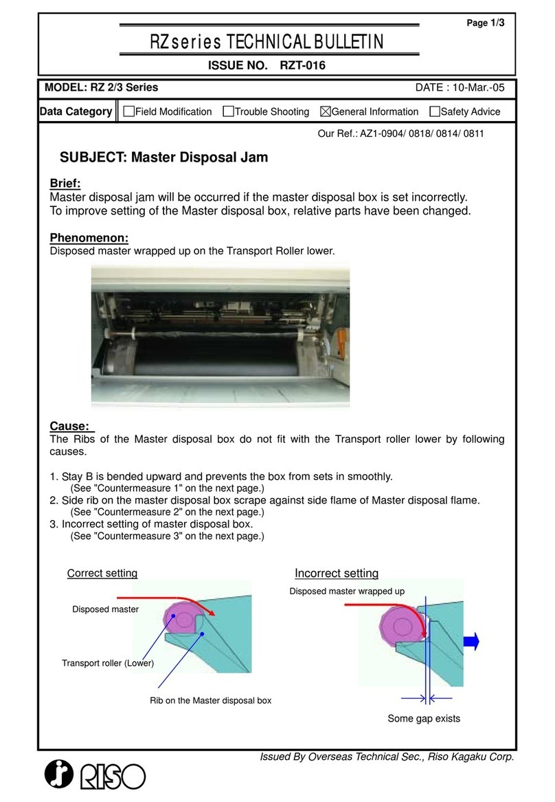
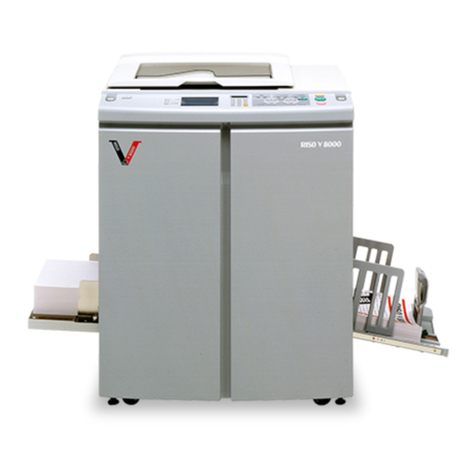
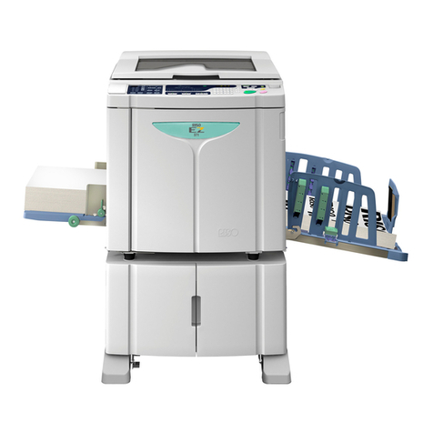
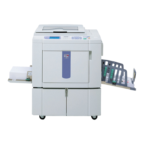
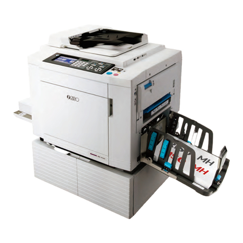
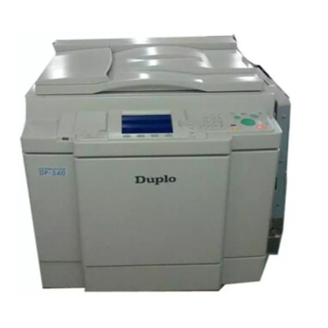
Riso RZ3xx Series User manual

RISO Inc. Technical Communications
us.riso.com
Copyright : 2005 Riso Kagaku Corporation
All Rights Reserved. This Technical Manual was prepared and
written for the exclusive use of RISO International Group Certified
Dealers. Reproduction and/or transmittal of this material in any
form or by any means, including photocopying or recording of the
information is strictly prohibited without the consent of a member
of RISO International Group.
RISO INTERNATIONAL GROUP
RISO KAGAKU CORPORATION (JAPAN) RISO DEUTSCHLAND GMBH (GERMANY)
RISO, INC. (U.S.A.) RISO FRANCE (FRANCE)
RISO EUROPE LIMITED (U.K.) RISO IBERICA (SPAIN)
RISO HONG KONG (HONG KONG) RISO CANADA (CANADA)
RISO UK (U.K.) ZHUHAI RISO TECHNOLOGY (CHINA)
RISO THAILAND LIMITED (THAILAND) RISO AFRICA (SOUTH AFRICA)
RISO KOREA LIMITED (KOREA) RISOGRAPH ITALIA (ITALY)
RZ2xx
RZ3xx
SERIES
TECHNICAL MANUAL
REVISION 3.0
FEBRUARY2005

RISO Inc. Technical Communications
us.riso.com
INDEX
CHAPTER 1 :MAINTENANCE
CHAPTER 2 :MACHINE SUMMARY
CHAPTER 3 :MAIN DRIVE
CHAPTER 4 :FIRST PAPER FEED SECTION
CHAPTER 5 :SECOND PAPER FEED SECTION
CHAPTER 6 :PRESS SECTION
CHAPTER 7 :PAPER EJECTION SECTION
CHAPTER 8 :PRINT DRUM SECTION
CHAPTER 9 :CLAMP UNIT
CHAPTER 10 :MASTER REMOVAL SECTION
CHAPTER 11:FBORIGINAL SCANNING SECTION ( RZ3 SERIES )
CHAPTER 12 :FBORIGINAL SCANNING SECTION ( RZ2 SERIES )
CHAPTER 13 :AF SCANNING SECTION
CHAPTER 14 :MASTER MAKING SECTION
CHAPTER 15 :OTHER PRECAUTIONS
CHAPTER 16 :PANEL MESSAGES
CHAPTER 17 :TEST MODE
CHAPTER 18 :ELECTRICAL COMPONENTS
CHAPTER 19 :WIRING DIAGRAM ( RZ2 SERIES )
CHAPTER 20 :WIRING DIAGRAM ( RZ3 SERIES )

RISO Inc. Technical Communications
us.riso.com
CHAPTER 1: MAINTENANCE
[ 1 - 1 ]
Contents
Preface..................................................................................................................................... 1-2
Caution ..................................................................................................................................... 1-3
Warning.................................................................................................................................... 1-4
1.Work Precautions............................................................................................................... 1-5
2.JIGs.................................................................................................................................... 1-8
3.Exterior Cover Removal ..................................................................................................... 1-9
4.Opening the PCB bracket................................................................................................. 1-13
CHAPTER 1: MAINTENANCE

RISO Inc. Technical Communications
us.riso.com
CHAPTER 1: MAINTENANCE
[ 1 - 2 ]
Preface
This manual provides Technical Service Information for the RISO PRINTER model RZ series.
This manual provides procedures for removing and installing major components. Following these procedures
will minimize machine malfunctions. This information and format will also increase technical representatives'
awareness and experience regarding repairs necessary to insure end-user satisfaction.

RISO Inc. Technical Communications
us.riso.com
CHAPTER 1: MAINTENANCE
[ 1 - 3 ]
[Handling of Lithium Battery]
- Never fail to follow the following instructions when you discard the used
lithium battery.
1. Never let the battery short-circuited.
If the (+) and (-) terminals contact each other or metal materials, the battery will
be short-circuited. If the batteries are collected and stored inorderly or one upon
another, the above-mentioned case will occur.
- DANGER -
If the battery is short-circuited, it will heat up and may in some cases explode into
fire.
2. Never heat up the battery.
- DANGER -
If you heat the battery up to more than 100 degrees Celsius or put it into the fire,
it may burn dangerously or explode.
3. Never disassemble the battery or press it into deformation.
- DANGER -
If you disassemble the battery, the gas pouring out of the inside may hurt your
throat or the negative lithium may heat up into fire.
If the battery is pressed into deformation, the liquid inside may leak out of the
sealed part or the battery may be short-circuited inside an explode.
4. Never fail to keep the battery out of reach of children.
If you put the battery within reach of children, they may swallow it down.
Should they swallow the battery, immediately consult the doctor.
[Replacement of the Lithium Battery]
1. The lithium battery must be replaced by a trained and authorized service
technician.
2. The battery must be replaced only with the same or equivalent type
recommended by the manufacturer.
3. Discard used batteries according to the manufacturer’s instructions.
CAUTION

RISO Inc. Technical Communications
us.riso.com
CHAPTER 1: MAINTENANCE
[ 1 - 4 ]
!! WARNING !!
Important Safety Precautions
1. Always disconnect electrical supply before placing hands in the
machine.
I. To avoid injuries:
Be sure to disconnect the electrical power before disassembling, assembling, or when
making adjustments on the machine.
II. Protection of the machine:
Make sure to turn OFF the power to the machine before plugging or unplugging the
electrical connectors, or when connecting a Meter.
2. WARNING:
The back light tube of LCD of the Control Panel on this Model contains mercury
which must be recycled or disposed of as hazardous waste.
3. Always connect electrical connectors firmly.
I. To avoid electrical failure:
The connectors must be connected firmly together and onto the PCBs.
Press on the ends of the connectors and then on the middle to ensure a firm fit.
II. Protection of the electrical components:
The electrical components may be damaged due to short circuits caused by a loose
connector.
FIRST
Wire harness connector
THEN
Press the center, firmly.
Press the ends.
0116

RISO Inc. Technical Communications
us.riso.com
CHAPTER 1: MAINTENANCE
[ 1 - 5 ]
Type Tip size Shaft length, etc.
Phillips screw driver
No. 2
No. 2
No. 2
No. 1
( 25 0 mm)
( 100 mm– 1 50 mm)
(stubby type)
(75 mm–100 mm)
High frequency
driver 2.5 mm
5. 0 mm 4.0 mm 3.0 mm
2. 5 mm 2.0 mm 1.5 mm
(For 3.0mm, 2 pieces required )
Spanners
Hex w renches
Standard
screw driver
Nut dr iv er
(box driver)
5 mm 5. 5 mm 7 mm
8 mm 10 mm 13 mm
Monkey
6 mm
3 mm
1.8 mm
( 100 mm– 1 50 mm)
( 100 mm– 1 50 mm)
(precision type)
8 mm
7 mm
( 100 mm– 1 50 mm)
( 100 mm– 1 50 mm)
Type Rem arks
Steel scale 150 mm
Feeler gauge
Radial cutting pliers
Pl ie r s
Nipper
Small flashlight
Multimeter
Soldering iron 20 W–30 W
File Flat, round
1. Work Precautions
When conducting maintenance work, be careful to avoid injury caused by springs or the sharp
edges of sheet metal.
Inspection
If you discover any defects or problems during an inspection, fix the problems or if necessary take steps
such as replacing a part.
Removal
Check the problem area. At the same time, examine the cause of the problem and determine whether
the part needs to be removed or disassembled. Next proceed according to the procedures presented in
the Technical Manual. In cases where, for example, it is necessary to disassemble areas with large
numbers of parts, parts which are similar to each other, or parts which are the same on the left and right,
sort the parts so that you do not mix them up during reassembly.
(1) Carefully sort the removed parts.
(2) Distinguish between parts which are being replaced and those which will be reused.
(3) When replacing screws, etc., be sure to use the specified sizes.
Assembly and Installation
Unless specified otherwise, perform the removal procedures in
reverse during assembly and installation. In cases where
protrusions or holes are provided to assist in positioning parts,
use them for accurate positioning and securing.
(Protrusions and holes for positioning parts Half pierced
section)
Tools
Using tools other than those specified can lead to injury or
damage screws and parts. Have all the tools necessary for the
work available.
[Standard Tool list]
Half-pierced section
0102
0103
0101

RISO Inc. Technical Communications
us.riso.com
CHAPTER 1: MAINTENANCE
[ 1 - 6 ]
Sensor types
• Photoelectric sensors may be broadly divided into
the following four types: interrupt types (U-
shaped), actuator types, reflective types, and
transmittive types.
• Magnetic sensors use Hall ICs, which react to the
magnetic force in magnets.
• Always turn off the power before plugging or
unplugging sensor connectors.
COM
N.C.
N.O.
N.C.
N.O.
COM
Electrical system work
• After removing wire bundles, fasten them with wire
bundle bands (bar lock ties) so that they will not
sag.
• When installing parts, be careful to avoid pinching
or damaging the wire bundles.
• If a fuse blows, always replace it with one with the
specified capacity.
• Using a fuse with a larger capacity can not only
damage parts, but may cause fires.
• Be careful not to drop image scanners, thermal
print heads, and other sensors as they can be
easily damaged.
Interrupt types
Reflective types
Transmittive types
Actuator types
Receiver
Sender
Receiver
Sender
Sender Sender
Receiver
Receiver
0104
0105 0106
0107
Reflective (prism) types
Send
Receive Prism
Wiring bundle bands
(bar lock ties)
Switch types
• Microswitches may be divided between normally
open (N.O.) types and normally closed (N.C.) types.
With an N.O. connection, an internal contact is
connected when the switch actuator is pressed.
With an N.C. connection, an internal contact is
disconnected when the switch actuator is pressed.
Note
The machine is comprised of many gears. When inspecting or replacing parts, apply grease to the
gears. If they are not properly greased, the gears may make abnormal sounds, and malfunctions or
mechanical problems may occur.

RISO Inc. Technical Communications
us.riso.com
CHAPTER 1: MAINTENANCE
[ 1 - 7 ]
Installation location
Do not install the machine in any of the following locations.
(1) Those subject to direct sunlight or any bright location such as by a window (If you must install in such
a location, put a curtain or the like over the window.).
(2) Those where the temperature changes drastically.
(3) Those that are too hot, cold, humid, or dry.
RECOMMENDED:
Temperature range: 15 degrees Celsius - 30 degrees Celsius
Humidity range: 40% - 70% No condensation allowed
(4) Those with radiant heat sources and any locations in the direct path of air from air conditioners or
heaters.
(5) Any poorly ventilated location.
(6) Dusty atmosphere.
(7) Any tilted location.
(Installation height difference: 10 mm max. front - rear, 10 mm max. left - right).
Electrical connection
- Plug the plug securely into the socket so that there is no problem with the contact in the power
supply plug section.
- Do not use any triplets or extension cords.
- Do not allow any other machine to stand on or crush the power cord.
Ground connection
- Always ground this machine to prevent electrical shock in the unlikely event of electrical leakage.

RISO Inc. Technical Communications
us.riso.com
CHAPTER 1: MAINTENANCE
[ 1 - 8 ]
2. JIGs
021-16007-005 Spring; Screen (2 pieces required)
Cut the ring end to make into hook, as shown on the
photograph, and attach wire tie bar on the other end.
016-16141-003 8mm Dia. x 160mm Shaft (JIG)
(2 pieces required)
Note:
The part numbers are subject to change without notice.
0108
0109

RISO Inc. Technical Communications
us.riso.com
CHAPTER 1: MAINTENANCE
[ 1 - 9 ]
3. Exterior Cover Removal
Front cover
(1) Open the front door, remove screws ( M4x8: 5pcs).
(2) Close the front door, remove screws (M4x8: 2pcs) on the paper feed side and screws (M4x8: 2pcs) on
the paper ejection side, and then dismount the front cover together with the front door.
Master-making unit cover; front
(1) With the machine power on, press the green release button to release the master-making unit and pull
out the unit.
(2) Remove screws (M4x8: 4 pcs) from the master-making unit front cover and remove the cover.
Master-making unit front cover
Front cover
Front door
0111

RISO Inc. Technical Communications
us.riso.com
CHAPTER 1: MAINTENANCE
[ 1 - 10 ]
Stage cover
(1) Open the stage cover, remove a screw (M4x10: 1pc each) from each of the two hinges (right and left) of
the stage cover, and then attach those screws in the screw holes behind. Lift the stage cover off the
machine.
Side cover; paper ejection
(1) Remove screws (M4x8: 2pcs), and dismount the side cover;paper ejection.
Rear side cover; paper ejection
(1) Remove the following covers.
- Rear cover
- Stage cover
- Scanner rear cover
- Scanner cover;paper ejection
(2) Remove screws (M4x8: 2pcs), and dismount the rear side cover;paper ejection.
Stage cover
Side cover; paper ejection
Rear side cover; paper ejection
0112

RISO Inc. Technical Communications
us.riso.com
CHAPTER 1: MAINTENANCE
[ 1 - 11 ]
Rear cover
Rear cover
- Remove screws (M4x8: 4pcs), and dismount the rear cover.
Download cover
- Remove screws(M4x8: 2pcs), and dismount the download cover.
Side cover; paper feed
- Remove screws ( M4x8: 2pcs), and dismount the side cover;paper feed.
Rear side cover; paper feed
(1) Remove the following covers.
- Rear cover
- Scanner cover; paper feed
(2) Remove screws ( M4x8: 2pcs), and dismount the rear side cover;paper feed.
Rear side cover; paper feed
Side cover;paper feed
Download cover
0113

RISO Inc. Technical Communications
us.riso.com
CHAPTER 1: MAINTENANCE
[ 1 - 12 ]
Scanner cover; paper feed
- Remove screws ( M4x8: 3pcs), and dismount the scanner cover;paper feed.
Scanner cover; paper ejection
- Remove screws( M4x8: 4pcs), and dismount the scanner cover;paper ejection.
Scanner cover; rear
(1) Dismount the stage cover.
(2) Remove screws(M4x8: 3pcs), and dismount the scanner cover;rear.
Operation panel
(1) Remove screws (M4x8: 3pcs)
(2) Lift up the operation panel after sliding to the front, unplug the connector, and then remove the operation
panel.
0114
Scanner cover; rear Scanner cover; paper ejection
Scanner cover; paper feed
Operation panel

RISO Inc. Technical Communications
us.riso.com
CHAPTER 1: MAINTENANCE
[ 1 - 13 ]
PCB bracket on which the power supply and
mechanical control PCBs are mounted.
4. Opening the PCB Bracket
(1) Switch off the power, and dismount the rear cover.
(2) Remove screws (M4x8: 5pcs) and slowly swing open the PCB bracket on which the power supply and
mechanical control PCBs are mounted.
0115

RISO Inc. Technical Communications
us.riso.com
CHAPTER 1: MAINTENANCE
[ 1 - 14 ]
MEMO

RISO Inc. Technical Communications
us.riso.com
CHAPTER 2: MACHINE SUMMARY
[ 2 - 1 ]
Contents
1.Cross-Sectional Diagram ................................................................................................... 2-2
2.Operation Outline ............................................................................................................... 2-3
3.Outline of Paper-feeding, Printing and Paper-ejection Operations...................................... 2-4
4.Outline of Master-removal, Master-making and Master loading Operations ....................... 2-5
5.Optional Accessories (Excludes China Market Models) ..................................................... 2-6
6.Machine Specification (Excludes China Market Models) .................................................... 2-7
RISO RZ 390 UI ................................................................................................................. 2-7
RISO RZ 370 EP ................................................................................................................ 2-8
RISO RZ 370 AW,AN......................................................................................................... 2-9
RISO RZ 310 UI ............................................................................................................... 2-10
RISO RZ 300 EP .............................................................................................................. 2-11
RISO RZ 230 EP .............................................................................................................. 2-12
RISO RZ 230 AW,AN....................................................................................................... 2-13
RISO RZ 220 UI, AS......................................................................................................... 2-14
RISO RZ 200 EP .............................................................................................................. 2-15
RISO RZ 200 AW............................................................................................................. 2-16
7.Feature List (Excludes China Market Models) ................................................................. 2-17
8.Optional Accessories (China Market Models only) ........................................................... 2-18
9.Machine Specification (China Market Models only) .......................................................... 2-19
RISO RZ 370 C ................................................................................................................ 2-19
RISO RZ 230 C ................................................................................................................ 2-20
10. Feature List (China Market Models only) ......................................................................... 2-21
CHAPTER 2: MACHINE SUMMARY

RISO Inc. Technical Communications
us.riso.com
[ 2 - 2 ]
CHAPTER 2: MACHINE SUMMARY
1. Cross-Sectional Diagram
Mirror carriage Lens Lamp carriage CCD
Cutter
Thermal print head
Write roller
Compressing plate
Master disposal box
Scraper roller
Pickup roller
Paper feed tray
Guide roller Timing roller Pressure roller Suction unit Paper receiving tray
7
5
12
3
4
9
6
8
RZ3 Series
Sends paper from the paper-feed tray one sheet at a time.
Stops the paper sent from the first paper-feed stage, and accurately
feeds it to the print drum and pressure section.
The pressure roller presses the paper firmly against the print drum for
printing and feeding.
Removes the printed paper from the print drum using the separator, and
sends it to the paper-receiving tray.
Supplies ink from the ink cartridge to the surface of the print drum for
printing.
Clamps the leading edge of a master.
Peels the master from the print drum after use, and discharges it into
the master disposal box.
The lamp carriage and mirror carriage move, and the CCD unit scans
the original on the scanner table.
Transports and creates a master using the thermal print head, then
sends the produced master to the print drum, and cuts the master
material.
First paper-feed area :
Second paper-feed area
Printing section
Paper-ejection section
Print cylinder (drum)
Clamp unit
Master-removal
section
Flatbed section
Master-making section
1
2
3
4
5
6
7
8
9
:
:
:
:
:
:
:
0201
:

RISO Inc. Technical Communications
us.riso.com
CHAPTER 2: MACHINE SUMMARY
[ 2 - 3 ]
Set an original, and press the Start key.
Master removal operation
Removes the used master from the
print drum, and sends it to the
master disposal box.
Master-making operation
The original is scanned by the
image sensor, and the image is
transferred onto a master by the
thermal print head.
Master loading operation
The produced master is wound
around the print drum and cut.
The proof-print is printed.
Printing operation
Paper is fed from the paper-feed tray one sheet
at a time for printing. The printed paper is ejected
out onto the paper-receiving tray.
2. Operation Outline

RISO Inc. Technical Communications
us.riso.com
[ 2 - 4 ]
CHAPTER 2: MACHINE SUMMARY
(1) When the print drum rotates, the scraper roller and
pickup roller also turn to feed paper. The stripper pad
allows only one sheet to pass through to the second
paper-feed area.
(2) The paper sent from the first paper-feed area contacts
the timing roller and guide roller, and stops temporarily.
This causes slight buckling of the paper.
(3) The timing roller and guide roller start rotating, feeding
paper to the pressure section. (This operation is
referred to as the “second paper-feed”. To prevent
tension from being placed on the end of the paper, the
scraper roller and pickup roller are free to spin.)
(4) When the paper is fed further in from the second paper-
feed area, the pressure roller rises to clamp the paper
between the drum and pressure roller to start the
printing operation.
(5) The printed paper is removed from the print drum by
the separator and separation fan. When the pressure
roller rises, the guide roller also moves up to prevent
tension from being placed on the tailing end of the
paper.
(6) Then, the suction fan sucks in the air to keep the paper
firmly on the transfer belts while the paper is carried to
the paper-receiving tray.
(7) The next sheet of paper is sent to the first paper-feed
area, and the guide roller lowers.
3. Outline of Paper-feeding, Printing, and Paper-ejection Operations
Scraper roller
Pickup roller
Stripper pad
Guide roller
Timing roller
Pressure roller
Separation fan
Separator
Transfer belt
0202
This manual suits for next models
1
Table of contents
Other Riso Disc Duplicator manuals
Popular Disc Duplicator manuals by other brands

BestDuplicator
BestDuplicator BD18xxL Controller user guide

Alesis
Alesis CD Twin LE Quick start owner's manual

Savin
Savin 3150DNP operating instructions

Rimage
Rimage Producer III 7100 reference guide

MicroBoards Technology
MicroBoards Technology Quic Disc QD-2 user manual

JMA
JMA SUPRACODE instruction manual

Addonics Technologies
Addonics Technologies Jasper II 1S JD2-325SN user guide

Codonics
Codonics Virtua E manual

Systor
Systor SYS3 Series user manual

MicroBoards Technology
MicroBoards Technology CopyWriter Series Specifications

Codonics
Codonics Virtua Technical brief

Primera
Primera CD Color Printer III user manual