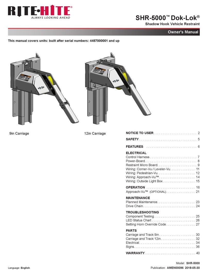
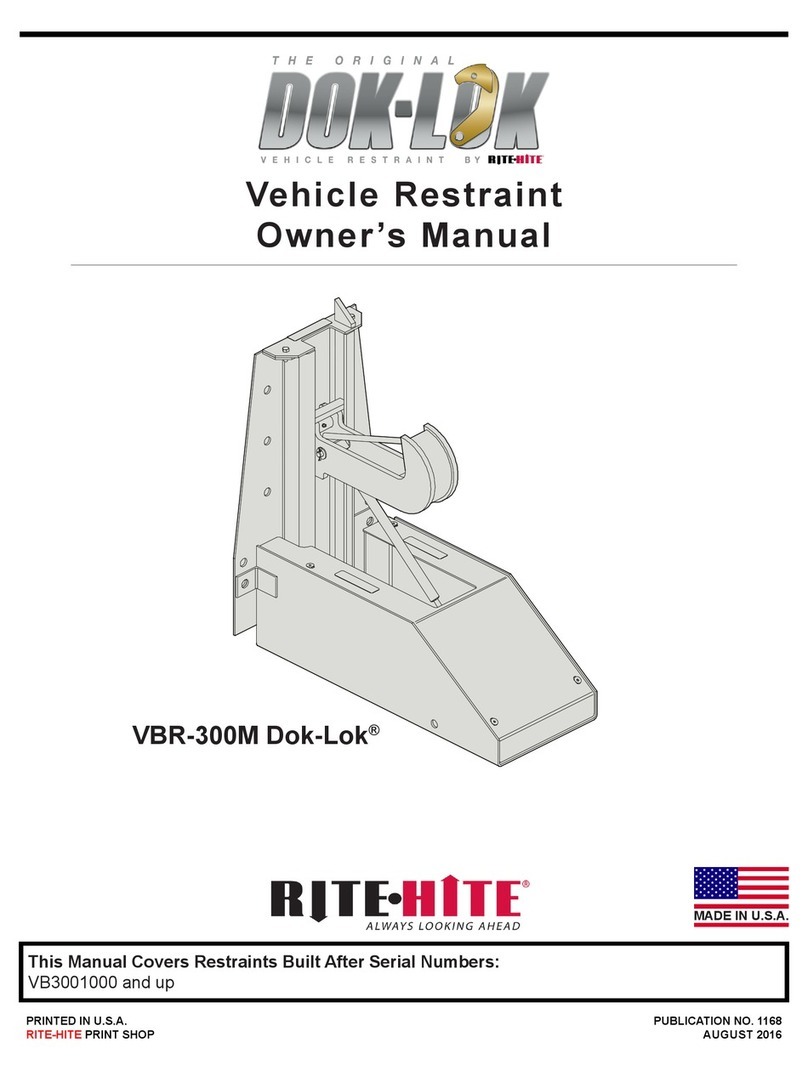
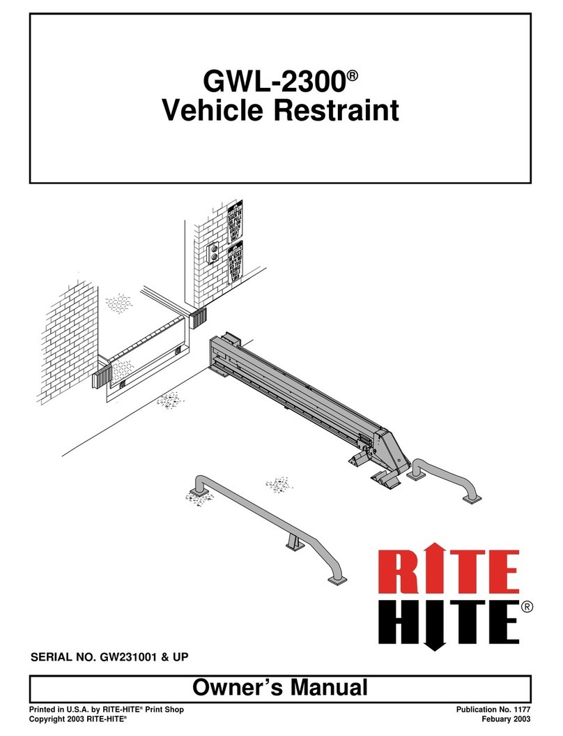
RITE-HITE DOK-LOK RHR-600 User manual

Model RHR-600
DOK-LOK
Printed in U.S.A Publication No. 1158
© 2001
RITE-HITE Corp.
August 2001
Owner’s Manual
Serial No. RHR001000 and UP
DL0001-0

2
RITE-HITE RHR-600 DOK-LOK Owner’sManual
Table ofContents
Introduction ................................................................................. 3
Owners Responsibility . . . . . . . . ................................................................. 4
DefinitionandFunction......................................................................... 5
Features .................................................................................... 5
TypicalInstallationViews ....................................................................... 7
Installation/ApplicationInformation ................................................................ 7
WiringDiagram ............................................................................. 12
ElectricalSchematic(Standard) ................................................................. 13
ElectricalSchematic(Optional).................................................................. 14
OperatingProcedure ......................................................................... 15
Maintenance................................................................................ 19
Troubleshooting ............................................................................. 21
ReplacementParts ........................................................................... 26
Patents
The
RITE-HITE
®products in this manual are covered by one or more of the following U.S. patents: 4,379,354; 4,443,150;
4,472,099; 4,560,315 (RE: 32,968); 4,605,353 (RE: 33,154); 4,634,334; 4,692,755; 4,843,373; 5,212,846; 5,297,921; 5,375,965;
5,453,735; 5,531,557; 5,553,987; 5,582,498; 5,664,930; 5,702,223; 5,762,459; 5,882,167; 5,964,572; 6,010,297; 6,074,157;
6,092,970; 6,106,212; 6,116,839; 6,190,109 and pending U.S. and foreign patent applications.
TrademarkAcknowledgements
RITE-HITE
®,
GUARDRITE
®,
SAFE-T-LIP
®,
HYDRACHEK
®,
WHEEL-LOK
™,
DOK-LOK
®,
DUAL-DOK
®,
SAFE-T-STRUT™,
and SAFE-T-GATE
™ are trademarksof
RITE-HITE
®.

RITE-HITE RHR-600 DOK-LOK Owner’sManual
3
Safety Warnings
LOCKOUT/TAGOUTProcedures
The Occupational Safety and Health Administration (
OSHA
)
requires, in addition to posting safety warnings and barricading
the workarea (including, but not limited to, trucking office and
loading docks), that the power supply has been locked in the
OFF position or disconnected. It is mandatory that an approved
lockout device is utilized. An example of a lockout device is
illustrated. The proper lockout procedure requires that the
person responsible for the repairs is the only person who has
the ability to remove the lockout device.
In addition to the lockout device, it is also a requirement to tag
the power control in a manner that will clearly note that repairs
are underway and state who is responsible for the lockout
condition. Tagout devices have to be constructed and printed
so that exposure to weather conditions, or wet and damp
locations, will not cause the tag to deteriorate or become
unreadable.
RITE-HITE
does not recommend any particular lockout device,
but recommends the utilization of an
OSHA
approved device
(refer to
OSHA
regulation 1910.147).
RITE-HITE
also
recommends the review and implementation of an entire safety
program for the Control of Hazardous Energy (LOCKOUT/
TAGOUT). These regulations are available through
OSHA
publication 3120.
Safety Conventions
Introduction
Read and understand this manual before attempting to install
or operate any
DOK-LOK
vehicle restraint. For best results,
have this product serviced by your authorized
RITE-HITE
representative.
The RHR-600
DOK-LOK
vehicle restraint by
RITE-HITE
is
intended to provide a safer workplace for workers in shipping
and receiving dockareas. The RHR-600
DOK-LOK
vehicle
restraint is an electro-mechanical restraint device that, when
properly installed and operated, retains a secure connection
between the truckand dock. Signal lights, warning horn and
signs provide instructions to the truckdriver and
DOK-LOK
vehicle restraint operator that a safe condition exists. The
DOK-LOK
vehicle restraint is operated by pressing push
buttons on an inside control panel.
NoticetoUser
Your local
RITE-HITE
representative provides the Planned
Maintenance Program (P.M.P.) which can be fitted to your
specific operation. Call your local representative or
RITE-HITE
at (800) 456-0600.
Figure 1
: LOCKOUT/TAGOUT
When workingwith electrical or electroniccontrols,
makesurethatthepower sourcehas been locked out
and tagged accordingto
OSHA
regulations and
approved local electrical codes.
DANGER
This is thehighestlevel statement.Failure tofollow
thelisted instructions will mostlikelyresultin severe
injuryor death.
This is a statementofserious hazard. Failure to
follow thelisted instructions could placethe
individual atriskofserious injuryor death.
Thestatementsusedwith this level ofwarningdeal
with asafeoperatingprocedure. If theprocedure is
ignored,thepossibility ofpersonal injurymayexist.
IMPORTANTis used todrawattention toaprocedure
thatneeds tobefollowed topreventmachine
damage.
DANGER
WARNING
CAUTION
IMPORTANT

4
RITE-HITE RHR-600 DOK-LOK Owner’sManual
Owners Responsibility
The following information is presented in
ANSI
Publication
MH30.1-2000 Section 4 Safety Requirements and
Considerations. The owner’s responsibilities include the
following:
1. The owner should recognize the inherent danger of the
interface between dockand transport vehicle. The
owner should, therefore, train and instruct operators in
the safe use of dockleveling devices in accordance with
the information provided below.
The manufacturer shall publish, provide to the initial
purchaser, and make the following information readily
available to owners:
— Installation instructions,
— Recommended initial and periodic inspection
procedures,
— Maintenance procedures,
— Operating instructions,
— Descriptions or specifications for replaceable or
repairable parts,
— Tables to identify the grade (slope) for all variations
of length or configuration of the dockleveling
device, and
— Information identifying the maximum uncontrolled
drop encountered upon sudden removal of support
while within the working range of the equipment.
It shall be the responsibility of the owner to verify that
the material listed in this section has been received
and that it is made available for the instruction and
training of personnel entrusted with the use or
maintenance of the dockleveling device.
2. When a transport vehicle is positioned as closely as
practicable to a dockleveling device, there should be at
least 4"(100 mm) of overlap between the front edge of
the lip and the edge of the floor or sill of the transport
vehicle.
3. Nameplates, cautions, instructions, and posted
warnings shall not be obscured from the view of the
operating or maintenance personnel for whom such
warnings are intended.
4. Manufacturer’s recommended periodic maintenance and
inspection procedures in effect at date of shipment shall
be followed, and written records of the performance of
these procedures should be kept.
5. Dockleveling devices that are structurally damaged or
have experienced a sudden loss of support while under
load, such as might occur when a transport vehicle is
pulled out from under the dockleveling device, shall be
removed from service, inspected by the manufacturer’s
authorized representative, and repaired as needed
before being placed backin service.
6. The manufacturer shall supply replacement nameplates,
cautions or instruction labels, and operating and
maintenance manuals upon request of the owner. The
owner shall see that all nameplates and caution and
instruction markings or labels are in place and legible
and that the appropriate operating and maintenance
manuals are provided to users.
7. Modifications or alterations of dockleveling devices shall
be made only with written permission of the original
manufacturer. These changes shall be in conformance
with all applicable provisions of this standard and shall
be at least as safe as the equipment was before
modification. These changes shall also satisfy all safety
recommendations of the original equipment
manufacturer for the particular application of the dock
leveler.
8. When industrial trucks are driven on and off transport
vehicles during the loading and unloading operation, the
brakes on the transport vehicle shall be applied and
wheel chocks or positive restraints that provide the
equivalent protection of wheel chocks engaged.
NOTE
: The MH30 Committee recognizes the devices
intended to secure a transport vehicle to a loading
dockby mechanical means. However, no standards
currently exist for the strength, construction or
attachment of the underride guard on a transport
vehicle. It is therefore recommended that users of
such positive restraint devices review the:
— Means of attachment to the transport vehicle,
— Strength of the overall connection,
— Proper coordination of the actuation of devices
with any signaling system used, and
— Need to use wheel chocks.
9. In selecting dockleveling devices, it is important to
consider not only present requirements but also future
plans or adverse environments.

RITE-HITE RHR-600 DOK-LOK Owner’sManual
5
Definition and Function
The RHR-600
DOK-LOK
vehicle restraint is an electro-
mechanical, self-aligning restraint device used to secure trucks
and semi-trailers with an intact Rear Impact Guard (R.I.G.) to
the face of a loading dock.Thisisachievedbyhooking the
R.I.G. with an electrically powered steel hook. This prevents
forward movement of the truck/trailer that may create an unsafe
void between the face of the dockand the rear end of the truck/
trailer as a forklift travels from the loading dockonto the trailer;
or to create an obstruction noticeable to the truckdriver, should
the driver accidentally try to pull the truck/trailer away while it is
being serviced.
The proper or improper activation of the hookis monitored by:
•VISUALCONTROL
— One set of flashing green or red lights located at the
inside of the building for the forklift operator, and one
set located outside of the building for the truckdriver. In
addition to the lights, there are three instruction signs.
• AUDIO CONTROL
— A horn will sound at the inside of the building, warning
the forklift operator if there is no R.I.G.present,orifthe
engagement is improper. In this case, the trailer must
be secured by other means (wheel chocks, etc.) prior to
servicing trailer.
Prerequisite for proper hookengagement is that the trailer is
parked firmly against a 4"(trade standard) thickdockbumper.
The activation/deactivation is solely controlled from the inside
of the building by momentarily depressing either the LOCK
(raise) button or the UNLOCK (lower) button.
The normal mode of the hookis in the lower stored position,
showing a flashing red light (trailer not secured) at the inside of
the building and a flashing green light (trailer free to move to or
away from the loading dock) at the outside of the building.
Once the trailer is parked, the dockattendant will depress the
LOCK button. This will raise the hookto engage the R.I.G.As
soon as the R.I.G. is properly locked, there will be
simultaneous light change — the inside will change from red to
green flashing (trailer secured) and the outside will change
from green to red flashing (do not move trailer). After the
service is completed, the dockattendant will have to depress
the UNLOCK button which then will return the hookto its lower
stored position.
A proper hookengagement is achieved when the hookraises
unobstructed to fully trap the horizontal cross member of the
R.I.G. Assembly. An improper hookengagement is if the
horizontal cross member of the R.I.G. is missing, obstructed, or
it is bent or located so far toward the rear axle of the trailer that
it will prevent the free passage of the hook. In either case, the
lights will stay in a non-serviceable mode and a horn will
sound. At this point, the trailer must be secured by other means
(example: wheel chocks) in order to become serviceable.
Features
Refer to
Figure 2
for locations of these features:
R.I.G.
Acronym used for the Federally mandated
rear impact
guard
located on the rear of over the road trailers to
prevent accidental underride by automobiles.
Roller Track Assembly
Mounted to the loading dockwall to guide the carriage
assembly in a vertical plane and transmit the creep or pull
out force from a trailer to the loading dockwall.
Carriage Roller Assembly
Comprised of a steel roller housing, a pre-lubricated
needle bearing to allow easy movement of the carriage
assembly.
CarriageReturn Springs
Bias the carriage assembly to its upward stored position
and to maintain contact with the R.I.G. while servicing a
trailer.
Lower SpringBar
Provides a connection between the carriage assembly and
roller trackassembly using carriage return springs.
CarriageAssembly
Sloped front provides self-positioning by the R.I.G.and
restrains the trailer once the hookhas been activated by
the dockattendant.
CarriageAssemblySlopeExtension
Allows trailers with lower R.I.G.s to be serviced by the
DOK-LOK
vehicle restraint.
Hook
Entraps R.I.G. to prevent trailer from rolling/creeping away
from the dock.
Motor Assembly
Provides means of moving the hookbetween its stored
and active positions.
SpringCovers with LipGuide
Protect the springs and keep debris out of the roller track
assembly. Right hand cover has an integral lip guide which
is used to guide the lip past the roller trackassembly in a
below dockend load condition.
LimitSwitches,Control Harness,Control Box, Outside
Light Box, and Signage
Combination of these components is used to control the
RHR-600
DOK-LOK
vehicle restraint and provide audio/
visual communications to the dockattendant and trailer
driver.

6
RITE-HITE RHR-600 DOK-LOK Owner’sManual
Figure 2
: RHR-600
DOK-LOK
Features

RITE-HITE RHR-600 DOK-LOK Owner’sManual
7
Typical Installation Views
Installation/Application Information
A
DOK-LOK
vehicle restraint may be installed on dockswithor
without levelers. Consult
RITE-HITE
for proper application.
Follow the six(6) step installation procedure below:
1. Inspect
DOK-LOK
vehicle restraint materials.
2. Install roller trackplate.
3. Install
DOK-LOK
vehicle restraint to roller trackplate.
4. Install electrical components.
5. Install signs.
6. Test operation.
Inspect
DOK-LOK
Vehicle RestarintMaterials
Open and inspect all materials. Refer to
Figure 2
. Immediately
report any damage or material shortage. Study component
assemblies and determine their proper locations. Refer to
Figure 26
and
Figure 27
.
Install Roller Track Plate
The RHR-600
DOK-LOK
vehicle restraint is shipped
assembled. The trackroller plate must be disassembled from
the
DOK-LOK
vehicle restraint to begin installation. To
disassemble:
1. Remove motor cover.
2. Remove spring cover and springs. Refer to
Figure 4
.
3. Remove nuts from spring bar.
4. Roll
DOK-LOK
vehicle restraint out of roller trackplate.
Be careful to keeprollersontheaxles. Refer to
Figure
4
.
Figure 3
: Flush Mount RHR-600
DOK-LOK
with Leveler in Recessed Pit
Postsafety warningsandbarricade workarea,at
dock level and atground level,toprevent
unauthorized use ofthe dock position.
Whether thereisaleveler or not, a4" thick bumper is
required. DONOTinstall a
DOK-LOK
vehicle restraint
on dockswithout4"thick bumpers. For thicker
bumpers consultfactory.
DANGER
IMPORTANT
Figure 4
: Removing Motor Cover, Spring Covers and Springs

8
RITE-HITE RHR-600 DOK-LOK Owner’sManual
Install roller trackplate onto dockface at specified location by
welding to an embedded steel plate or by using the 15 concrete
anchors provided in conjunction with welding to pit steel and a
leveler frame. Refer to
Figure 5
.
NOTE
: Trim roller trackplate, as necessary, up to a
maximum of 5"from the bottom. Refer to
RITE-HITE Application Guidelines
.
NOTE
: Some mechanical docklevelers have an adjusting
nut access hole in the leveler front subframe. If the
RHR-600
DOK-LOK
vehicle restraint roller track
interferes with the access hole, the trackplate must
be cut to allow access. Refer to
Figure 8, page 9
.
NOTE
: Some levelers may be slightly recessed within pit. A
shim must be inserted between the roller trackplate
and the leveler front subframe and then must be
welded in place. Refer to
Figure 9, page 9
for
adding a necessary lip guide.
Anchor Installation Instructions
1. Put roller trackplate in place.
2. Drill hole of 5/8"diameter and minimum of 4-5/8"deep.
Clean out hole.
3. Insert anchor and drive flush with roller trackplate,
making certain that the threaded wedge is put in first. Do
not disassemble anchor prior to installation.
4. Install all anchors and torque to 100 ft-lbs.
NOTE 1
For site specific installation refer to
RITE-HITE
Application information provided with
DOK-LOK
vehicle restraint. When in doubt, call
RITE-HITE
Representative or
RITE-HITE
Customer Service
at (800) 456-0600.
•Aplumb roller track plateisrequired. If thedock face
is notplumb/perpendicular,contact your
RITE-HITE
representativeor
RITE-HITE
at(800) 456-0600.
•Thecarriage roller track cannotbebentor deformed.
Straighten or replaceasrequired.
IMPORTANT
Fifteen (15) concreteanchors are provided with each
vehicle restraint.You mustinstall an anchor in each
roller track platehole except those plug-welded to
embedded steel
Figure 5
: Anchoring Roller TrackPlate
IMPORTANT
See NOTE 1.

RITE-HITE RHR-600 DOK-LOK Owner’sManual
9
WeldingInstallation Instructions
If the installation being worked on is a “reinstallation” the
following electrical connections must be disconnected prior to
welding. MakesuretoLOCKOUT/TAGOUT the power at the
fused disconnect, then, remove motor and limit switch
connections from the control harness located inside the motor
cover and disconnect the ground located in the outside junction
box. Once all welding procedures have been completed,
reconnect all wires.
NOTE 1
:
Figure 6
– Plug weld all holes that are in contact
with pit curb steel. All fifteen (15) holes must be
either plug welded or anchored.
NOTE 2
:
Figure 6
– Shims must be the full length of the
roller trackmounting plate. Minimum electrode
must be 1/8” 7018 or better.
NOTE 3
:
Figure 6
–Neverinstall
DOK-LOK
vehicle
restraint directly onto concrete blockor brickdock
face.
NOTE 4
:
Figure 6
– When welding
DOK-LOK
vehicle
restraint, disconnect power and ground leads to
DOK-LOK
vehicle restraint and leveler.
NOTE 5
:
Figure 6
– Due to actual conditions, total mounting
height may be different. Refer to
RITE-HITE
Application Guidelines
for actual mounting height.
Special Application Installation
NOTE 1
:
Figure 9
–Shimasrequired behind trackangles
(1/2"thickminimum bar stock) and weld in place.
Never weld on the RHR-600
DOK-LOK
vehicle
restraintafter motor is wired intothecontrol boxand
thepower totheboxis on. Electrical currentfromthe
welder can “feedback”through thecircuitand
damagethemotor and other components.
Figure 6
: Welding Roller Track, Front View
Add length tolipguide as required (supplied by
others).Weld in placeasshown in
Figure 9
.Donot
weld toleveler frontframeangle.
IMPORTANT
See NOTE 1
-
NOTE 5
.
See NOTE 5
IMPORTANT
Figure 7
: Welding Roller Track, Side View
Figure 8
:RollerTrack,FrontView
Figure 9
:RollerTrack,SideView
See NOTE 1.

10
RITE-HITE RHR-600 DOK-LOK Owner’sManual
Install
DOK-LOK
to Roller Track Plate
1. Attach the four (4) springs to the lower spring bar.
2. Pull upward and slide over top spring mount on the track
roller plate. Then slide the carriage assembly into the
roller track.Referto
Figure 10
.
3. Position and bolt the lower spring bar to the bottom of
the
DOK-LOK
vehicle restraint carriage.
4. Install the spring covers and motor cover.
NOTE
:If
DOK-LOK
vehicle restraint is being relocated,
follow lubrication instructions in
Maintenance,
page 19
.
Install Electrical Components
DOK-LOK
Power Source
If the incoming electrical power for the RHR-600
DOK-LOK
vehicle restraint is taken from a nearby electrical appliance,
i.e., overhead door opener, verify that the amperage is in
accordance with local and federal codes.
The
DOK-LOK
vehicle restraint requires 120V, single phase
power, 60 Hzpower and 10 amps of current, for a 1/4 HP
motor, to operate properly.
Tw o ( 2 )
DOK-LOK
vehicle restraints can be hooked into one
(1) 20 amp branch circuit breaker per the 1999 National
Electrical Code Paragraph 430-53.
When in doubt, call your
RITE-HITE
representative or
RITE-HITE
at (800) 456-0600.
The
DOK-LOK
vehicle restraint assembly includes a 63"long
flexible wiring harness. Also provided are the control boxwith
lights and the outside signal light box. The outside junction box,
conduit fittings and wire are provided by others. Quality
material and workmanship should be used. Refer to
Figure 11,
page 11
for component location information. Refer to
Figure
12, page 12
through
Figure 14, page 14
for wiring information.
When liftingcarriage(approx. 110 lbs.)use lifting
device(ex.crane,jack).Liftingbyhand maycause
back injury.
Figure 10
: Installing Carriage to Roller Track
CAUTION
When workingwith electrical or electroniccontrols,
makesurethatthepower sourcehas been locked out
and tagged accordingto
OSHA
regulations and
approved local electrical codes.
All componentsmustbeconnected toaSAFETY
EARTHGROUNDwhere indicated. TheSAFETY
EARTHGROUNDmustconformtothe1999 National
ElectricCode Section 250-50section (a)or section (c)
for a groundingelectrode system.
DANGER
IMPORTANT

RITE-HITE RHR-600 DOK-LOK Owner’sManual
11
Install Signs
There are two (2) driver warning signs and one (1) inside
operator sign supplied with each
DOK-LOK
vehicle restraint.
Because of the many ways signs can be mounted, hardware is
not supplied. Mount both outside signs on the right hand side
of the
DOK-LOK
vehicle restraint. The mirror-image sign is
usually mounted above the lower sign and near the outside
signal lights. (Mirror-image permits the truckdriver to read sign
from truckmirror.) Mount the inside sign nexttothecontrolbox.
All signs must be installed.
NOTE 1
:
Figure 11
– Some docks may have dock/truck
seals (or shelters) installed or planned which are
larger than standard. Outside light, sign location,
and mounting should be studied before
proceeding to avoid interference.
NOTE 2
:
Figure 11
–Ifrequired for special reasons, signs
may be trimmed for fit. NEVER cut or eliminate
sign letters/words.
NOTE 3
:
Figure 11
– Attach signs with concrete anchors or
screws. Nails are not acceptable.
NOTE 4
:
Figure 11
– NEVER put conduit in front of signs. A
clear view of both exterior signs and the single
interior sign must be maintained at all times.
OperatingTest
Follow
Operating Procedure, page 15
.
Figure 11
: Suggested Component Location
See NOTE 1,NOTE 2,NOTE 3,NOTE 4.

12
RITE-HITE RHR-600 DOK-LOK Owner’sManual
WiringDiagram
NOTE 1
:
Figure 12
–Allwiretobe#14 gauge. All conduit
andfittingstobe3/4"or per local code.
NOTE 2
:
Figure 12
– Refer to
Figure 11, page 11
for motor
and limit switch cord routing and wire harness
installation instructions.
NOTE 3
:
Figure 12
–ACmotor rating 1/4 HP, 120V, 1PH, 60
Hz,5.2A,(F.L.A.) reversible, intermittent duty.
NOTE 4
:
Figure 12
– If outside lights do not work,check
connections of wires #40, 41 and 42.
NOTE 5
:
Figure 12
– SAFETYEARTH GROUND required.
Figure 12
: Installation Wiring Diagram
See NOTE 5
See NOTE 4
See NOTE 3
See NOTE 1.

RITE-HITE RHR-600 DOK-LOK Owner’sManual
13
Electrical Schematic(Standard)
Figure 13
: Electrical Schematic (Standard)

14
RITE-HITE RHR-600 DOK-LOK Owner’sManual
Electrical Schematic(Optional)
Figure 14
: Electrical Schematic (Optional)

RITE-HITE RHR-600 DOK-LOK Owner’sManual
15
OperatingProcedure
STORED
Hookis in the STORED position. Inside light is flashing red
alerting forklift operator unsafe condition exists. Outside light is
flashing green alerting truckdriver it is safe to backin.
•Before loadingor unloadingavehicle atyour loading
dock while usinga
DOK-LOK
vehicle restraint, always
visuallyinspect tobesurethatthe
DOK-LOK
vehicle
restrainthookentrapstheR.I.G. assembly.If a
condition occurs thatcannotberemedied by backing
thetrailer firmlyagainstthedock bumpers,secure the
trailer by other means.
•Besurethatthe area around theR.I.G. assemblyis
free ofplates or other obstructions.
•Alwaysoperatethe
DOK-LOK
vehicle restraintfrom
thetopofthe dock.
•Inspect all restraintlightsandhorns dailytomake
certain theyworkproperly.
•Performmaintenanceonrestraintsinaccordancewith
Maintenance, page 19
ofthis manual.
•
DOK-LOK
vehicle restraintsshould beoperated only
by authorized personnel whohave read and
understand the Owner’s Manual.
•Call
RITE-HITE
at(800) 456-0600 with anyquestions.
FAILURETOFOLLOWTHESEPROCEDURESCOULD
ALLOWUNEXPECTED TRAILER/LOADINGDOCK
SEPARAT ION RESULTINGINDEATHORSERIOUS
INJURY!
WARNING
Figure 15
: STORED Position

16
RITE-HITE RHR-600 DOK-LOK Owner’sManual
RestraintLocking, LOCK Button Pressed
Trailer has backed into loading dockand is parked firmly
against dockbumpers. Hookrotates from stored position to
entrap R.I.G. Inside light is steady red alerting the operator that
an unsafe condition exists and hookis in transit. Outside light is
flashing red alerting truckdriver not to move.
If horn sounds, go to FAULT, otherwise go to Restraint
LOCKED.
RestraintLOCKED
Once the R.I.G. is entrapped by the hook,alocked condition
exists. Inside light is flashing green alerting the forklift operator
a safe condition exists. Outside light is flashing red alerting
truckdriver not to move.
If during loading/unloading the inside light turns red and the
horn sounds, press LOCK button to secure the R.I.G.
Figure 16
: Restraint LOCKING
Visually inspect to ensure that the
DOK-LOK
vehicle
restraint hooksecurely entraps the R.I.G. of the trailer
being serviced before operating the dockleveler.
WARNING
Figure 17
: Restraint LOCKED

RITE-HITE RHR-600 DOK-LOK Owner’sManual
17
RestraintUNLOCKING, UNLOCK Button Pressed
Hooktravels from the locked position to the STORED position.
Inside light is steady red alerting the operator that an unsafe
condition exists and hookis in transit. Outside light is flashing
red alerting truckdriver not to move. If horn sounds go to
FAULT,otherwisegotoSTORED.
FAULT StateFromLOCKINGState
Hookcannot entrap the R.I.G. This could be due to a R.I.G.
that is located too far toward the rear axle, bent, obstructed, or
missing. Inside light is flashing red and horn is pulsing, alerting
the forklift operator that the trailer is not locked. Outside light is
flashing red alerting the truckdriver not to move.
If the trailer is parked firmly against the dockbumpers go to
HORN OVERRIDE. If not, press UNLOCK to clear the fault,
have trailer backup and repeat Restraint LOCKING.
FAULT StateFromUNLOCKINGState
Hookcannot rotate to the STORED position. The hookcould
be caught on the R.I.G. or another part of the trailer. Inside light
is flashing red and horn is pulsing, alerting the forklift operator
that the trailer is not locked. Outside light is flashing red
alerting the truckdriver not to move.
Make sure trailer is parked firmly against the dockbumpers. If
not, press LOCK to entrap R.I.G., have trailer backup and
repeat Restraint UNLOCKING.
Figure 18
: Restraint UNLOCKING
Figure 19
: Fault State

18
RITE-HITE RHR-600 DOK-LOK Owner’sManual
HORN OVERRIDE State,HORN OVERRIDE
Button Pressed after SecuringTrailer by
AlternateMeans
An alternate means of securing the truckmust be used (i.e.
wheel chocks). Inside lights are flashing red and green
alerting the forklift operator the trailer is secured by other
means. Outside light is flashing red alerting the truckdriver
not to move.
To return to STORED, press the HORN OVERRIDE button
followed by the UNLOCK button.
Figure 20
: HORN OVERRIDE State

RITE-HITE RHR-600 DOK-LOK Owner’sManual
19
Maintenance
NOTE
: If a leveler is installed at the RHR-600
DOK-LOK
vehicle restraint location, it may be necessary to raise
the leveler to remove the
DOK-LOK
vehicle restraint
carriage assembly from the roller track. Use care
when removing
DOK-LOK
vehicle restraint carriage
assembly from roller trackto not pull control harness
wires out of wall mounted junction box.Raisethe
leveler, insert and secure the
SAFE-T-STRUT
, and
LOCKOUT/TAGOUT the power source.
Daily
1. Remove debris around
DOK-LOK
vehicle restraint.
2. Verify inside, outside lights and horn are working.
3. Replace damaged or missing light bulbs and lenses.
4. Repair, remount, or replace outside and inside signs as
required.
5. Inspect dockbumpers. Missing bumpers must be
replaced.
180Days
1. Perform all
Daily
maintenance.
2. Grease rollers at fittings located on the top and bottom
axle. Use
Mobilith
SHC220No.2grease(orequivalent
temperature range lithium based grease). Seven (7) to
eight (8) pumps should be used for first 180 Day
maintenance. Two (2) to three (3) pumps at subsequent
180 Day maintenance intervals.
3. Verify clutch toque is greater than 500 in-lbs at the hook
shaft.
4. Inspect outside junction and light box. They should be
rigidly mounted. If loose or damaged, inspect all wires
and wire connections.
5. Checkthat all concrete anchor bolts are torqued to 100
ft-lbs.
6. Inspect flexible electrical harness from
DOK-LOK
vehicle restraint to junction box.Lookfor kinks, crushed
areas, etc.
7. Perform operational test after all maintenance repairs
and adjustments are complete.
8. Inspect dockbumpers. Four inches (4")ofprotectionis
required. Worn, torn, loose or missing bumpers must be
replaced.
360Days
1. Perform all
Daily
and
180 Days
maintenance.
2. Checkand tighten, if necessary, motor drive chain. To
tighten see
Figure 21, page 20
.
3. Spray lube chain using spray grease (Zep 2000
recommended).
4. Lubricate (Zep 2000) limit switch mounting bracket
between drive sprocket and cam.
When workingwith electrical or electroniccontrols,
makesurethatthepower sourcehas been locked out
and tagged accordingto
OSHA
regulations and
approved local electrical codes.
Postsafety warningsandbarricade workarea,at
dock level and atground level,toprevent
unauthorized use ofthe dock position.
Asafeworkplacerequires all lightsandthehorn to
beworkingproperly.DONOTuse
DOK-LOK
vehicle
restraintifpartsarebroken or missing.
When liftingcarriage(approx. 110 lbs.)use lifting
device(ex.crane,jack).Liftingbyhand maycause
back injury.
Maintenance may be requiredmorefrequently at loading
docksexposed to harsh environments (extreme climates,
corrosive chemicals, frequency of usage, etc.). Consult
RITE-HITE
if these conditions exist for accelerated
maintenance requirements.
DANGER
DANGER
WARNING
CAUTION
IMPORTANT

20
RITE-HITE RHR-600 DOK-LOK Owner’sManual
DriveChain Adjustment
Periodically inspect the drive chain for dirt and chain slack.
Open the motor enclosure for inspection. Clean the chain with
solvent. After cleaning, spray the chain with a good quality
chain spray type lubricant.
The drive chain should not have more than 1/4"slack. Refer to
Figure 21
. To tighten chain:
1. Open motor enclosure and loosen the four (4) motor
mounting bolts.
2. Pry the motor assembly forward, in the slotted holes,
until the chain is tight with proper alignment between
sprockets. Hold in this position and tighten the four (4)
motor mounting bolts to 105 in-lbs in increments of
10 in-lbs. Tighten in pattern shown. See
Figure 21
.
3. Test for proper chain alignment.
4. Close the motor enclosure.
When workingwith electrical or electroniccontrols,
makesurethatthepower sourcehas been locked out
and tagged accordingto
OSHA
regulations and
approved local electrical codes.
DANGER
Figure 21
: Maintenance and Lubrication
Table of contents
Other RITE-HITE Lock manuals
Popular Lock manuals by other brands

YLI
YLI YM-500 Wiring instructions

Wittkopp
Wittkopp Primor 100 installation instructions

Gantner
Gantner GAT ECO.Side Lock 7000 BA Installation, commissioning & operation

Soyal
Soyal LK1201A quick start guide

keylezz
keylezz Turn BasicPlus Customer's operating and assembly instructions

AMSEC
AMSEC ESL15 operating instructions