RITE-HITE Wheel-Lok GWL-2300 User manual

GWL-2300®
Vehicle Restraint
Owner’s Manual
Printed in U.S.A. by RITE-HITE®Print Shop Publication No. 1177
Copyright 2003 RITE-HITE®Febuary 2003
SERIAL NO. GW231001 & UP

2
Pub. No. 1177 - Febuary 2003
RITE-HITE GWL-2300 Owner’s Manual
INTRODUCTION . . . . . . . . . . . . . . . . . . . . . . . . . . . . . . . . . . . . . . . . . . . . . . . . . . . . . . . . . . . . . . . . . . . . . . . . .. . 2
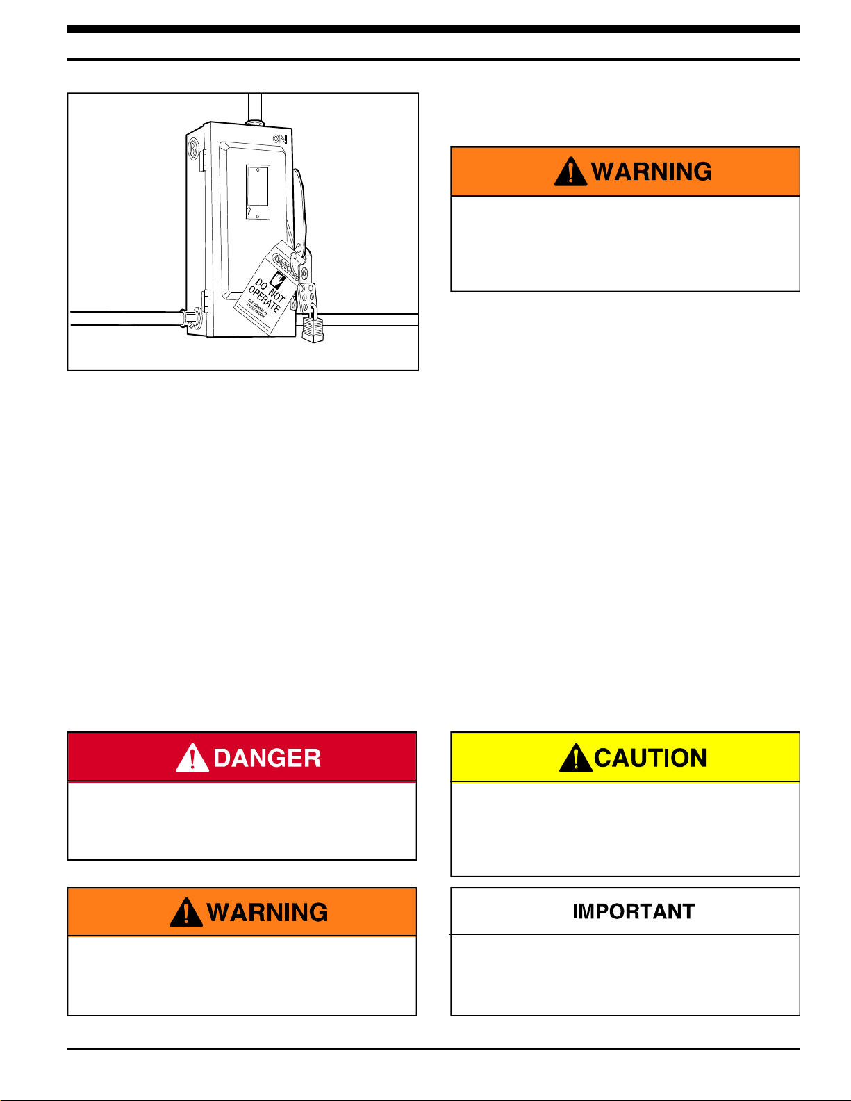
SAFETY WARNINGS . . . . . . . . . . . . . . . . . . . . . . . . . . . . . . . . . . . . . . . . . . . . . . . . . . . . . . . . . . . . . . . . . . . . . . . 3
OWNER RESPONSIBILITY . . . . . . . . . . . . . . . . . . . . . . . . . . . . . . . . . . . . . . . . . . . . . . . . . . . . . . . . . . . . . . . . . . 4
DEFINITION AND FUNCTION. . . . . . . . . . . . . . . . . . . . . . . . . . . . . . . . . . . . . . . . . . . . . . . . . . . . . . . . . . . . . . . . . 5
FEATURES . . . . . . . . . . . . . . . . . . . . . . . . . . . . . . . . . . . . . . . . . . . . . . . . . . . . . . . . . . . . . . . . . . . . . . . . . . . . . . 6
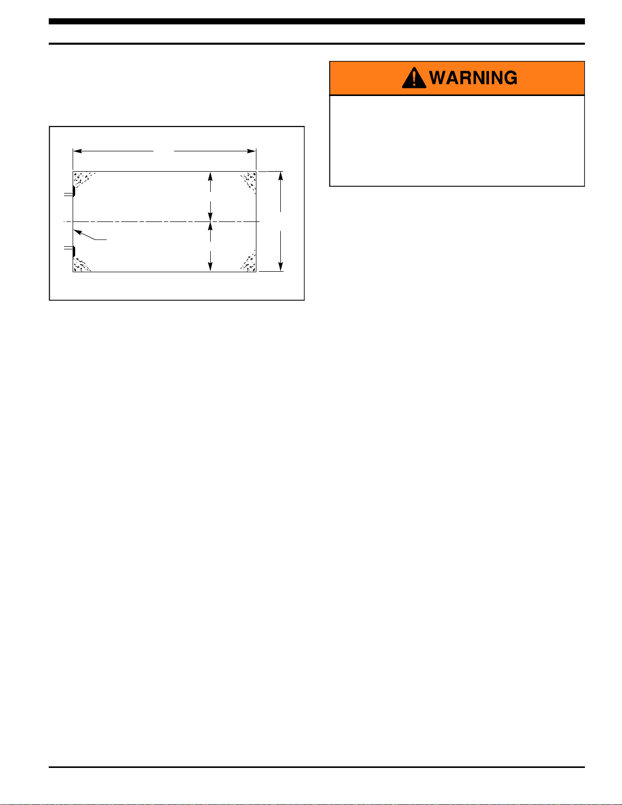
INSTALLATION INSTRUCTIONS. . . . . . . . . . . . . . . . . . . . . . . . . . . . . . . . . . . . . . . . . . . . . . . . . . . . . . . . . . . . . . 8
WIRING DIAGRAM . . . . . . . . . . . . . . . . . . . . . . . . . . . . . . . . . . . . . . . . . . . . . . . . . . . . . . . . . . . . . . . . . . . . . . . 14
ELECTRICAL SCHEMATIC . . . . . . . . . . . . . . . . . . . . . . . . . . . . . . . . . . . . . . . . . . . . . . . . . . . . . . . . . . . . . . .. . . 15
OPERATING PROCEDURES & TESTING . . . . . . . . . . . . . . . . . . . . . . . . . . . . . . . . . . . . . . . . . . . . . . . . . . . . . . 18
MAINTENANCE (BASED ON TYPICAL APPLICATIONS OF 8 TRUCKS PER DAY). . . . . . . . . . . . . . . . . . . . . . . . 23
TROUBLESHOOTING . . . . . . . . . . . . . . . . . . . . . . . . . . . . . . . . . . . . . . . . . . . . . . . . . . . . . . . . . . . . . . . . . . . . . . . 25
HORN OVERRIDE CODE AND DIAGNOSTICS . . . . . . . . . . . . . . . . . . . . . . . . . . . . . . . . . . . . . . . . . . . . . . . . . . . . 28
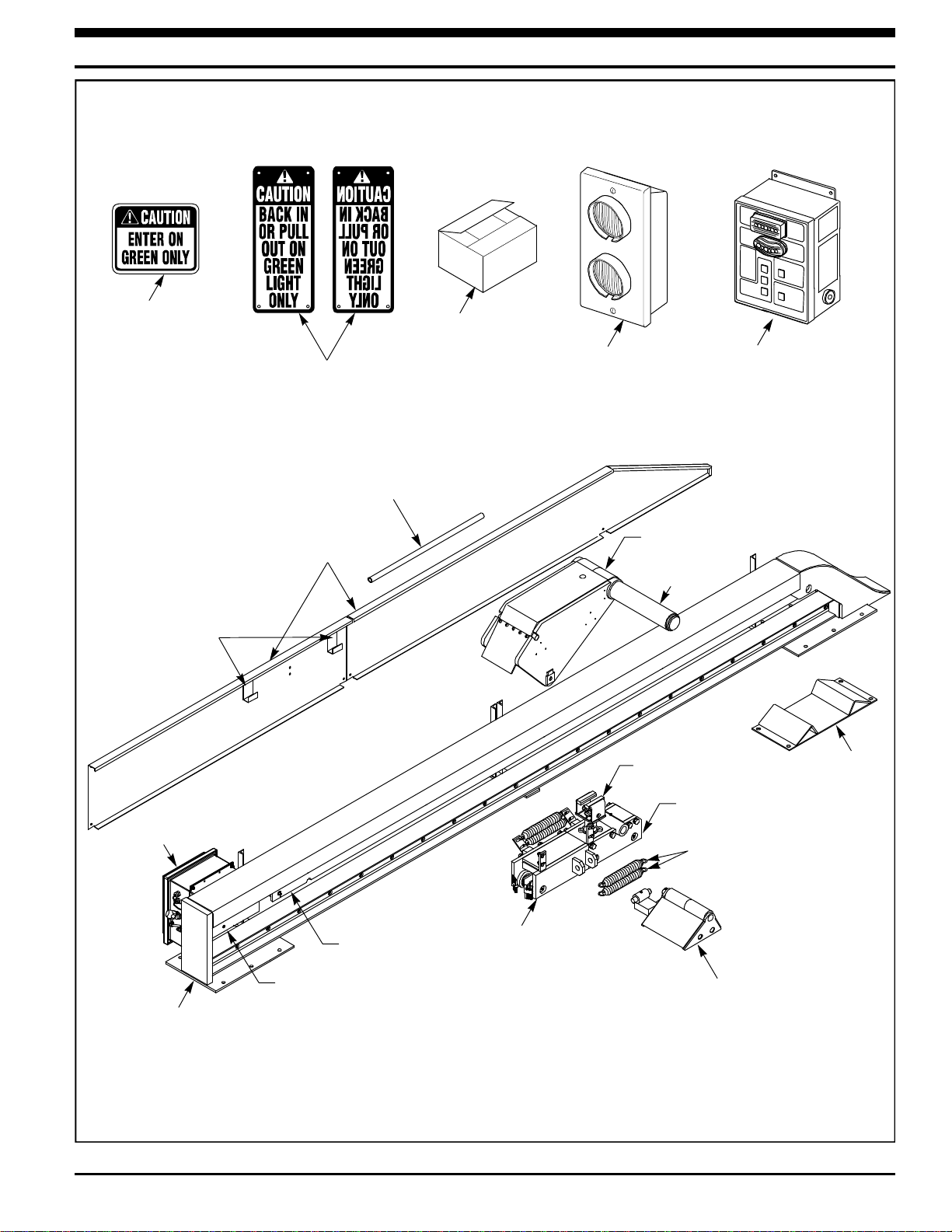
REPLACEMENT PARTS . . . . . . . . . . . . . . . . . . . . . . . . . . . . . . . . . . . . . . . . . . . . . . . . . . . . . . . . . . . . . . . . . . . . . . 30
TABLE OF CONTENTS
INTRODUCTION
Read and understand this manual before attempting to install or operate. For best results, have this product serviced
by your authorized RITE-HITE®representative.
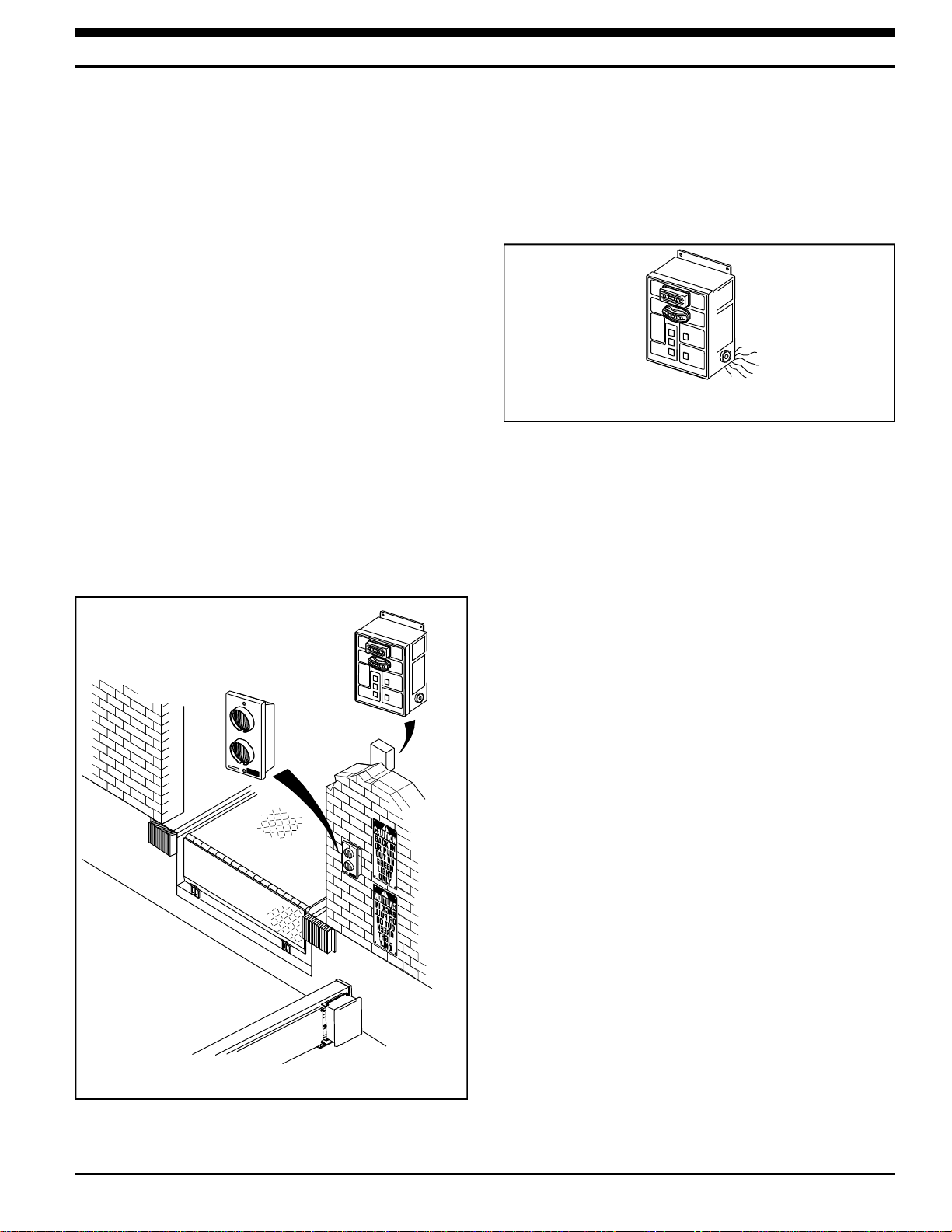
The GWL-2300 vehicle restraint by RITE-HITE is intended to provide a safer workplace for workers in shipping and
receiving dock areas. The GWL-2300 vehicle restraint is a restraint device that, when properly installed and operated,
retains a secure connection between the truck and dock. Signal lights, warning horn and signs provide instructions to
the truck driver and GWL-2300 vehicle restraint operator that a safe condition exists. The GWL-2300 vehicle restraint
is operated by pressing push buttons on an inside control box.
NOTICE TO USER
Your local RITE-HITE®representative provides a Planned Maintenance Program (P.M.P.) which can be fitted to your
specific operation. Call your local representative or the RITE-HITE®Corporation at 414-355-2600.
The RITE-HITE®products in this manual are covered by one or more of the following U.S. patents: 4,531,248;
4,560,315 (RE: 32,968); 4,570,277; 4,605,353 (RE: 33,154); 4,634,334; 4,692,755; 4,744,121; 4,819,770; 4,843,373;
4,865,507; 4,920,598; 4,995,130; 5,040,258; 5,111,546; 5,212,846; 5,271,183; 5,299,386; 5,311,628; 5,323,503;
5,375,965; 5,440,772; 5,442,825; 5,453,735; 5,531,557; 5,546,623; 5,553,987; 5,582,498; 5,664,930; 5,702,223;
5,762,459 (RE: 37,570); 5,882,167; 5,964,572; 6,010,297; 6,065,172; 6,070,283; 6,074,157; 6,085,375; 6,092,970;
6,106,212; 6,116,839; 6,190,109; 6,220,809; 6,627,016; 6,238,163; 6,322,310; 6,311,352; 6,360,394; 6,368,043,
6,431,819; and pending U.S. and foreign patent applications. RITE-HITE®, LEVEL-RITETM, GUARDRITE®, SAFE-T-
LIP®, HYDRACHEK®, WHEEL-LOKTM , DOK-LOK®, DUAL-DOK®, and SAFE-T-GATE®are trademarks of RITE-HITE®
Corporation.

RITE-HITE GWL-2300 Owner’s Manual
SAFETY WARNING
Pub. No. 1177 - Febuary 2003
3
LOCKOUT/TAGOUT PROCEDURES
The Occupational Safety and Health Administration (OSHA) requires, in addition to posting safety warnings and
barricading the work area (including, but not limited to, trucking office and loading docks), that the power supply has
been locked in the OFF position or disconnected. It is mandatory that an approved lockout device is utilized. An
example of a lockout device is illustrated. The proper lockout procedure requires that the person responsible for the
repairs is the only person who has the ability to remove the lockout device.
In addition to the lockout device, it is also a requirement to tag the power control in a manner that will clearly note that
repairs are under way and state who is responsible for the lockout condition. Tagout devices have to be constructed
and printed so that exposure to weather conditions, or wet and damp locations, will not cause the tag to deteriorate or
become unreadable.
RITE-HITE®does not recommend any particular lockout device, but recommends the utilization of an OSHA approved
device (refer to OSHA regulation 1910.147). RITE-HITE®
also recommends the review and implementation of an entire
safety program for the Control of Hazardous Energy (Lockout/Tagout). These regulations are available through OSHA
publication 3120.
When working with electrical or electronic con-
trols, make sure that the power source has been
locked out and tagged out according to OSHA
regulations and approved local electrical codes.
The statements used with this level of warning
deal with a safe operating procedure. If the
procedure is ignored, the possibility of personal
injury may exist.
This is the highest level statement. Failure to
follow the listed instructions will most likely
result in severe injury or death.
IMPORTANT is used to draw attention to a
procedure that needs to be followed to prevent
machine damage.
This is a statement of serious hazard. Failure to
follow the listed instructions could place the
individual at risk of serious injury or death.
Figure 1 - LOCKOUT/TAGOUT

OWNER RESPONIBILITY
RITE-HITE GWL-2300 Owner’s Manual
4
Pub. No. 1177 - Febuary 2003
1. The owner should recognize the inherent danger
of the interface between dock and transport
vehicle. The owner should, therefore, train and
instruct operators in the safe use of dock
equipment in accordance with the information
provided below. The manufacturer shall publish,
provide to the initial purchaser, and make the
following information readily available to owners:
•Installation instructions
•Recommended initial and periodic inspections
procedures
•Maintenance procedures
•Operating instructions
•Descriptions or specifications for replaceable or
repairable parts
•Tables identifying the grade (slope) for all
variations of length or configuration of the dock
equipment, and
•Information identifying the maximum
uncontrolled drop encountered upon sudden
removal of support while within the working
range of the equipment.
It shall be the responsibility of the owner to verify
that the material listed in this section has been
received and that it is made available for the
instruction and training of presonnel entrusted with
the use or maintenance of the dock equipment.
2. When a transport vehicle is parked at a loading
dock, it is important that the vehicle is relatively
perpendicular to the dock face and in close contact
with at least one of the dock bumpers.
3. Nameplates, cautions, instructions, and posted
warnings shall not be obscured from the view of
operating or maintenance personnel for whom
such warnings are intended.
4. Manufacturer’s recommended periodic maintenance
and inspection procedures in effect at date of
shipment shall be followed, and written records of
the performance of these procedures should be
kept.
5. As with any piece of machinery, dock equipment
requires routine maintenance, lubrication, and
adjustments. Your local RITE-HITE®representative
offers owners the option of a Planned Maintenance
Program (P.M.P.). As part of this service, your local
RITE-HITE®representative will do all routine
maintenance, lubrication, and adjustments.
6. Dock equipment that is structurally damaged shall
be removed from service, inspected by a
manufacturer’s authorized representative, and
repaired as needed before being placed back in
service.
7. The manufacturer shall make available
replacement nameplates, caution/instruction
labels, and operating/maintenance manuals upon
request of the owner. The owner shall see that all
nameplates, caution/instruction markings or labels
are in place and legible, and that the appropriate
operating/maintenance manuals are provided to
users.
8. Modifications or alterations of dock equipment
shall be made only with written permission of the
original manufacturer. These changes shall also
satisfy all safety recommendations of the original
equipment manufacturer for the particular
application of the dock equipment.
9. When industrial trucks are driven on and off
transport vehicles during the loading and unloading
operation, the brakes on the transport vehicle shall
be applied and wheel chocks or a positive
restrainting device shall be engaged.
10. In selecting dock equipment, it is important to
consider not only present requirements but also
future plans or adverse environments.

DEFINITION AND FUNCTION
RITE-HITE GWL-2300 Owner’s Manual
Pub. No. 1177 - Febuary 2003
5
The GWL-2300 vehicle restraint is a truck and trailer
locking system used to help secure trucks and trailers to
the face of a loading dock. The engagement mechanism
is positioned by the trailer as it approaches the loading
dock. The locking arm assembly, which blocks the rear
wheel of the truck or trailer, can then be engaged by
pressing the LOCK push button.
This prevents forward movement of the truck/trailer that
may create an unsafe void between the face of the dock
and the rear end of the truck/trailer as the forklift travels
from the loading dock onto the trailer; and creates an
obstruction noticeable (via outside lights) to the truck
driver, should the driver accidentally try to pull the truck/
trailer away while it is being serviced.
NOTE
There is no need to hold button to maintain its function.
Once a button is depressed, the GWL-2300 vehicle
restraint will lock or unlock for a preset time interval.
The normal mode of the restraint is the locking arm
assembly stored at the far end (away from the dock)
with the barrier arm on the approach. Inside lights
should be flashing red and outside lights should be
flashing green.
The proper activation of the barrier and the locking
mechanism is monitored by:
Visual Controls – one set of flashing green and red
lights located inside the building for the dock personnel,
and one set located outside the building for the truck
driver. See Figure 2.
Audio Controls – a horn sounds inside the building,
warning dock personnel when the locking mechanism is
not properly activated. In this case, the truck or trailer
must be secured by other means (wheel chocks etc.)
prior to servicing the trailer. See Figure 3.
Outside Light Box
With Red And
Green Lights
Inside Control Box
With Red And
Green Lights
FIGURE 3 - AUDIO CONTROLS
FIGURE 2 - VISUAL CONTROLS

See Figure 4 for locations of these features.
HYDRAULIC CYLINDER
Moves the Lifting Rails back and forth, thus raising or
lowering the locking pawl into place.
POWER UNIT ENCLOSURE
Houses the 120 VAC Hydrualic Power Unit and terminal
block assembly.
BARRIER SHAFT
The shaft which serves as the restraining obstruction in
front of the rearmost tire. It is connected to the locking
arm assembly.
BARRIER RAMP
The assembly that the barrier shaft stores in. Barrier
ramp is used to protect the barrier shaft when a
truck/trailer backs into place.
FRAME ASSEMBLY
The main weldment which is bolted onto the approach.
It acts as a guide/rail for the locking arm assembly,
trigger trolley, and lock trolley.
LOCKING ARM ASSEMBLY
The assembly which is rotated up into its UP position
when a trailer backs into the dock.
LOCKING ARM TROLLEY ASSEMBLY
Locking arm trolley assembly holds the locking arm
assembly to the frame and houses the pawl assembly.
LIFTING RAILS
The component which is pushed by the hydraulic
cylinder. It rides upon diagonal slotted plates along the
frame. The vertical motion drives the locking pawl into
the ratchet.
PAWL ASSEMBLY
Assembly which is driven upward into the ratchet by the
Lifting Rails when the unit is locked.
TRIGGER ASSEMBLY
Component which is contacted by the rearmost tire of a
trailer. When a tire engages the trigger, it will pull the
locking arm assembly into its UP position, and pull the
locking arm assembly along the frame assembly.
TRIGGER TROLLEY ASSEMBLY
The trigger trolley assembly holds the trigger assembly
to the frame.
EXTENSION SPRINGS
The extension springs connect the locking arm trolley to
the trigger trolley.
LOCK SENSOR (SW1)
Communicates to the control box whether or not the unit
is locked. (Not shown, See page 26)
UNLOCK SENSOR (SW2)
Communicates to the control box whether or not the unit
is unlocked. (Not shown, See page 26)
CONTROL BOX, OUTSIDE LIGHT BOX,
AND SIGNAGE
The combination of these components are uses to
control the function of the GWL-2300 Wheel Restraint
and provide audio/visual communication to the dock
attendant and the trailer driver.
6
Pub. No. 1177 - Febuary 2003
RITE-HITE GWL-2300 Owner’s Manual
FEATURES

Pub. No. 1177 - Febuary 2003
7
RITE-HITE GWL-2300 Owner’s Manual
Control
Box
Outside
Signs
Maintenance
Strut
Power Unit
Enclosure
Frame
Assembly
Lifting Rails
Hydraulic
Cylinder Trigger
Assembly
Barrier
Ramp
Locking Arm
Assembly
Barrier Shaft
Pawl
Assembly
Locking Arm
Trolley Assembly
Trigger Trolley
Assembly
Side
Covers
Inside
Sign Anchor
Kit
Outside
Lights
Maintenance Strut
Storage Hooks
Extension Springs
FIGURE 4 - FEATURES OF GWL-2300

INSTALLATION INSTRUCTIONS
RITE-HITE GWL-2300 Owner’s Manual
8
Pub. No. 1177 - Febuary 2003
The performance of any machine can be no better than
the installation and application. The GWL-2300 vehicle
restraint requires only ordinary application and
installation skills using good workmanship and quality
materials.
Follow the 7-step Installation Procedure:
1. Inspect GWL-2300 vehicle restraint components.
2. Install GWL-2300 vehicle restraint frame assembly.
3. Install wheel guides.
4. Install barrier ramp.
5. Install electrical components.
6. Fill and bleed hydraulic system.
7. Install signs.
8. Test operation.
INSPECT COMPONENTS
Open and inspect all materials. Refer to Figure 4.
Immediately report any damage or material shortage.
Study component assemblies and determine their
proper locations. Refer to Figures 30 - 39.
GWL-2300 VEHICLE RESTRAINT POWER
SOURCE
On occasion, the incoming electrical power for the
GWL-2300 vehicle restraint is taken from a convenient
nearby electrical appliance, i.e., overhead door opener.
Generally, there is no problem using this sort of power
source; you must, however, verify that the amperage is
in accordance with local and federal codes.
The GWL-2300 vehicle restraint requires 120V, single
phase 60 Hz power and 5 amps of current. Four (4)
GWL-2300 vehicle restraints can be hooked into one (1)
20 amp feeder circuit per the current N.E.C. Paragraph
#430-53.
WHEN IN DOUBT, CALL YOUR RITE-HITE
REPRESENTATIVE OR RITE-HITE AT (800) 456-0600.
Post safety warnings and barricade work area,
at dock level and at ground level, to prevent
unauthorized use of the dock position. When working with electrical or electronic
controls, make sure that the power source has
been locked out and tagged according to OSHA
regulations and approved local electrical codes.
All components must be connected to a
SAFETY EARTH GROUND where indicated. The
SAFETY EARTH GROUND must conform to the
current National Electric Code Section 250-81
section (a) or section (c) for a grounding
electrode system.

RITE-HITE GWL-2300 Owner’s Manual
Pub. No. 1177 - Febuary 2003
9
CONCRETE APPROACH REQUIREMENTS
Verify the approach meets the following criteria:
1. The approach must be concrete, 137" wide by 300"
long x 6" minimum thickness. See Figure 5.
2. The approach must be free of discontinuities (such
as cracks, potholes, etc.) greater than 1/4" where
the trigger will travel. In addition, the trigger must
not travel more than 1" below the base plate of the
rail assembly without surface preparation under
trigger path. See Figure 6, Section A-A.
3. The GWL-2300 vehicle restraint can be installed
and shimmed up to 1" without modification. If
greater than 1" of shimming is necessary, longer
anchors and trigger bridge plate will be required.
Please consult RITE-HITE.
TRENCH DRAINS
1. If the GWL-2300 vehicle restraint crosses a trench
drain parallel to the dock face, the drain grate must
be bridged with a 1/4" thick steel plate where the
trigger will travel.
2. If the trench drain lies in the same position as a
GWL-2300 vehicle restraint anchor plate, a steel
plate must be welded to the mounting pad and
anchored to the approach. See Figure 6.
Never weld on the GWL-2300 vehicle restraint
when the electrical components are connected
to the main control box and the power to the
box is “ON”. Electrical current from the welder
can “FEED BACK” through the circuit and could
cause injury or damage electrical components.
137"
Ref.
300"
Dock
Face 68-1/2"
C
L
68-1/2"
FIGURE 5 - CONCRETE PAD

10
Pub. No. 1177 - Febuary 2003
RITE-HITE GWL-2300 Owner’s Manual
INSTALLATION OVER A TRENCH DRAIN AND SHIMMING INSTRUCTIONS
Rearmost
Trench Drain
Position
Bridge Plate
For Trigger
Travel Path
If Necessary.
Anchor And
Weld In-place
1/4"Typ.
16"
11-1/2"
Bridge Plate For
Trench Drains 1/4" Plate
Steel. Plate Width Must
Be 1/2" Wider Than
Mounting Plate To Allow
For Welding. Plate
Length Determined By
Location And Width
Of Drain.
C
L
55"
Ref.
C
L
Approach
Bumper Face
A
A
Shim Middle Frame Bar
Full Depth To Approach
17-1/2" To
Front Of Rear
Base Plate
Rearmost
Trench Drain Position Frontmost
Trench Drain Position
Trigger
Travel Path
Locate Anchor Tabs Away From
Trigger Travel Path. Anchor
Mounting Holes Must Be A Minimum
3" From Edge Of Trench Drain.
Locate Anchor Mounting Tabs On Both Sides Of Trench Drain
If Welding To GWL-2300 Mounting Plate Is Not Possible.
Shim Material Is Required If Welding
To GWL-2300 Frame Bar Plate
Section A-A
Side View
Top View
1" Max.
Allowable
Trigger
Approach
Shims
1/4"Typ.
Frontmost
Trench Drain
Position
Tube And I-Beam
Must Remain Parallel
Bevel Plate
Edges To Prevent
Roller Damage
Assembly
Level frame over
each base plate
FIGURE 6 — INSTALLATION OVER A TRENCH DRAIN AND SHIMMING
A maximum shimming of 1" thickness is
permitted for installations of the GWL-2300.
Make sure that solid metal shims are used.
Shims must fully support the mounting plate
and are secured in place with the mounting
anchors. Use the holes in the mounting plate
as a drilling guide. Consult RITE-HITE
Applications where more than 1" of shimming
is required.

Pub. No. 1177 - Febuary 2003
11
RITE-HITE GWL-2300 Owner’s Manual
INSTALL FRAME ASSEMBLY
LOCATE THE CENTERLINE
1. Secure a 20' length of string at the lower right edge
of the dock leveler pit at the dock face. Measure out
5' of string, and holding a piece of chalk at the end
of the 5' length of string, draw a large arc which
begins well before and extends past where you
expect the centerline to be. See Figure 7.
2. Repeat Step 1, this time beginning at the lower left
edge of the dock leveler pit at the dock face. Where
the two arcs intersect indicates one point of the
centerline.
3. Repeat Steps 1 and 2, using 20' of string instead of
5'. Use the intersections of both arcs as points to
snap a chalk line. This line is the centerline (Line A)
for the frame assembly.
LOCATE FRAME POSITION
1. Measure to the right of the centerline 52-1/2". Snap
a chalk line for Line B. To ensure Line B is parallel
to the centerline (Line A), measure and mark at
several locations. See Figure 7.
2. Measure 17-1/2" off each bumper face. Snap a
chalk line for Line C. See Figure 7.
POSITION FRAME
1. Remove side covers from rail assembly prior to
positioning and anchoring.
2.
Position the GWL-2300 vehicle restraint along the B
and C lines as shown in Figure 8. The front edge of
the rear mounting plate should be aligned with Line
C. The edge of the front and rear base plate should
be aligned with Line B. See Figure 8.
SHIM AND ANCHOR FRAME
1. Starting at one end of the frame assembly, see
Figure 6 for shimming instructions, drill anchor holes
using mounting plates as templates. Insert anchor
bolts, tapping each into the drilled holes with a
hammer so that the head of the anchor is as close
to the anchor plate as possible without causing the
frame to twist.
2.
After all concrete anchors have been inserted, using
a torque wrench, tighten each to 100 ft-lbs of
torque. Verify that dimension between top of I-beam
and tube is consistent, and frame stays level above
each base plate. See Figure 6.
20 Feet 20 Feet
5 Feet
Line C
5 Feet
17-1/2"
Loading Dock
52-1/2"
C
L
FIGURE 7 - LOCATING CENTERLINE
103"
Line C
55"
Ref.
Protective
Wheel Guide
(Optional)
52-1/2" 40"
12"
Loading Dock
C
L
52"
17-1/2"
283"
Ref.
127"
Ref.
10-1/4"
FIGURE 8 - ANCHORING TRACK

INSTALLATION WHEEL GUIDES
RITE-HITE GWL-2300 Owner’s Manual
12
Pub. No. 1177 - Febuary 2003
NOTE
If there is another loading dock on the right side of the
GWL-2300 vehicle restraint installation and this position
does not have wheel guides, it is required to install a
protective wheel guide. See Figure 8.
1. Measure 10-1/4" off the stored end mounting plate
and snap a chalk line.
2. Measure 52" off the centerline to the right, 51" left
and snap a chalk line.
3. Position short wheel guide (GWL-2300 vehicle
restraint side) so nearest mounting plate is 10-1/4"
from GWL-2300 vehicle restraint mounting plate
and inside edge of guide tube is 52" from the
centerline. See Figure 8.
4. Position long wheel guide so front most mounting
plate is aligned with the front most mounting plate
of the short wheel guide and so that the inside
edge of the guide tube is 51" from the centerline.
See Figure 8.
5. Measure and verify that there is 103" between
wheel guides. Adjust as required and anchor to
approach.
6. Insert concrete anchors and tighten, using a torque
wrench, to 100 ft-lbs.
INSTALL BARRIER RAMP
1. Position ramp at outer edge of barrier as shown in
Figure 9.
2. Verify locking arm clearance by manually lowering
and raising the locking arm weldment in and out of
the ramp. Use the maintenance strut located on
the inside of the rear side cover.
3. Insert (4) concrete anchors and torque to 100 ft-
lbs.
LOCKING RANGE
These operating instructions are intended for ALL DOCK
PERSONNEL who are involved in loading/unloading
trucks and trailers. GWL-2300 vehicle restraint is a
safety system used to accommodate trucks and trailers
with tire diameters ranging from 30" to 44", while the
rear axle is located at a maximum of 158" away from
the face of the loading dock. See Figure 10.
The locking arm is heavy. Lift it, using the
supplied strut (located on the inside of the
rear side cover), to the required position by
fully inserting the strut into the tube and then
moving the locking arm upwards in one
motion. Lift carefully and stand clear to avoid
pinching fingers or feet. Lifting by hand may
cause back injury. Secure the arm in the
elevated position against unintentional
movements. See Figure 9.
7"
Ramp
Location
10-1/4"
Wheel Guide
Location
Flush
13.25"
Ref.
FIGURE 9 - INSTALLING BARRIER RAMP
AND FRONT WHEEL GUIDE
Max.
158"
Min.
43"
FIGURE 10 - WHEEL POSITION RANGE
Always check that the vehicle is parked firm
against the bumpers before locking the
GWL-2300 vehicle restraint.

RITE-HITE GWL-2300 Owner’s Manual
Pub. No. 1177 - Febuary 2003
13
INSTALL ELECTRICAL COMPONENTS AND SIGNS
1. Mount control box, outside light box and signs as
shown in Figure 11.
2. Run conduit from control box to outside light box
and from outside light box to junction box. See
Figure 12.
3. Run 3/4” liquid tight flexible conduit from junction
box to power unit enclosure.
When working with electrical or electronic
controls, make sure that the power source has
been locked out and tagged according to OSHA
regulations and approved local electrical codes.
80"
1"
22"
96"
Junction Box Outside
Of Dock Bumpers
C
LLoading Dock
Control Box
Mounted Inside
Of Building
48"
18"
15"
Approach
Some Docks May Have Truck Seals (Or Shelters)
Installed Or Planned Which Are Larger Than
Standard. Outside Light And Sign Location
Mounting Should Be Studied Before Proceeding
To Avoid Interference.
Outside Light Box
Mounted Outside
Of Building
Reverse Letters
Caution Sign
Mounted Outside
Of Building
Caution Sign
Mounted Outside
Of Building
Interior Caution Sign
Mounted Inside
Of Building
Door Opening
(Reference)
Outside Edge Of Shelter
(If Equipped)
View From Outside Of Loading Dock
Junction Box NEMA 4 J.I.C., Size Per Current N.E.C. Section 370.16.
NOTE: Projection Of Box Not To Exceed 3-1/ 2".
FIGURE 11 - ELECTRICAL INSTALLATION AND SIGN LAYOUT

WIRING DIAGRAM
RITE-HITE GWL-2300 Owner’s Manual
To Customer
Power Supply
And Safety
Protection Device
30 Amp Rated
Fused Disconnect
With 10 Amp
Non-time Delay Fuse
(Suppled By Others)
NEMA 4 J.I.C. Box
(Supplied By Others)
(Waterproof)
4" x 4" x 3"
Suggested Size
(3" Max. Projection
From Wall Allowable)
From Inside Control Box
To Junction Box
Alternate Knockout
For Inside
Control Box Wiring
1
2
3
4
5
6
7
G
G
1
2
3
4
5
6
7
Power Unit Enclosure
1
2
3
4
5
6
7
G
G
1
2
3
4
5
6
7
To SW1 Limit Switch
To SW2 Limit Switch
From Junction Box
3/4" Flexible
Liquid Tight
(Supplied By Others)
Circuit
Breaker
RESET
button
To Customer Power Supply,
120V, 60Hz, 30 Amp Fused Disconnect
With 10 Amp Non-Time Delay Fusing
(Supplied By Others)
Control Box
Outside Lights
40 42
41
RED
GREEN
(8) Wires (11) Wires
FIGURE 12 - WIRING DIAGRAM
14
Pub. No. 1177 - Febuary 2003

RITE-HITE GWL-2300 Owner’s Manual
Pub. No. 1177 - Febuary 2003
15
ELECTRICAL SCHEMATIC (STANDARD)
Limit
Switch 1
Lock
Limit
Switch 2
Unlock
motor
lock
motor
unlock
no fuse
required
diagnostic
button
CPU
module
(SW1)
(SW2)
green
green
white
black
black
white
(4) (5) (6) (7)
ground lugs
NOTE: Use included female spade
connectors for installation.
LEGEND
label LED lamp
denotes field wiring
5631D028
outside light
common
outside light
green
outside light
red
(42)
(41)
(40)
to option module
motor
common
to customer power supply,
120V, 60Hz, 30 amp
fused disconnect with 10 amp
non-time delay fusing
(supplied by others)
ground
lugs
power
module
1A, 250V
control
fuse (3)
(2)
(1)
FIGURE 13 - ELECTRICAL SCHEMATIC (STANDARD)

ELECTRICAL SCHEMATIC (OPTIONAL
RITE-HITE GWL-2300 Owner’s Manual
16
Pub. No. 1177 - Febuary 2003
CPU
module
photoeye
inter-
connect
hydraulic
inter-
connect
raise
LEGEND
lable LED lamp
denotes field wiring
leveler/overhead door
stored interlock
mechanical/
FA inter-
connect
NOTE: Use included female spade
connectors for installation.
5631D029
unidox
inter-
connect
selector
switch
OFF ON
security
system
interface
output
unidox
inter-
connect
output
green
light
inter-
lock
output
option
module
circuit breaker
reset button
power
module
NOTE: The standard wiring is not shown in this drawing to better show the option module wiring.
For information on standard wiring, see previous page.
FIGURE 14 - ELECTRICAL SCHEMATIC (OPTIONAL)

RITE-HITE GWL-2300 Owner’s Manual
FILL AND BLEED HYDRAULIC SYSTEM
1. Using the maintenance strut, position the locking
arm assembly to a “locked” (up) position to
simulate a truck at the dock.
2. Fill hydraulic reservoir using the supplied (MIL-H-
5606) hydraulic fluid.
3. Press and hold the diagnostic button inside the
control box until the horn chrips (refer to Figure 13
on page 15).
4. Once horn chirps enter code 1-1-1-1 by using the
buttons on the face of the control box. Controls are
now in FILL mode. Holding the LOCK and
UNLOCK button will run the pump forward and
reverse.
5. Cycle the vehicle restraint to remove air from the
system. Add remaining hydraulic fluid. Stop cycling
once the cylinder extends and retracts without
hesitation.
6. Press diagnostic button inside control box to exit
FILL mode.
OPERATING TEST
The GWL-2300 vehicle restraint is now ready for the
initial test procedure, which must be carried out prior to
use of the device. Follow Operating Procedures, page
18.
Make sure that electrical schematics are in the control
box and that working area is clean and free of any
packaging material. The GWL-2300 vehicle restraint
should now be installed properly and ready for use.
Pub. No. 1177 - Febuary 2003
17
Post safety warnings and barricade work area,
at dock level and at ground level, to prevent
unauthorized use of the dock position.
Stand clear when you push the locking arm to
its stored position. The arm should only be
moved by hand for the initial installation and test
procedure by authorized and trained personnel.
NEVER leave the arm in the elevated position.
If light sequence differs from what is described
above, check the electrical installation. If the
situation can not be resolved, call RITE-HITE for
assistance. NEVER leave the job site with the
GWL-2300 vehicle restraint not working properly.
Store the locking arm in its rest position
before you leave the site.

NO TRUCK PRESENT
If the GWL-2300 vehicle restraint is in the UNLOCKED
position (shaft assembly is down and stored in barrier
ramp), the Light Communication System should give the
following signals:
1. OUTSIDE light flashing GREEN, which indicates
that a vehicle may pull into or out of the loading bay.
2. INSIDE light flashing RED, which indicates that
loading or unloading is not permitted, since the truck
is not secured against the building. See Figure 15.
LOCKING A TRUCK/TRAILER
It is assumed that the loading bay is empty (no truck).
The outside GREEN light and the inside RED light are
flashing, the barrier is down. A truck can now approach
the loading position. As the truck backs in, it will activate
the trigger, causing the locking arm to come up. The
mechanism will automatically adjust to the correct wheel
size. The truck will move locking arm and trolleys into
position automatically. When the truck is parked firmly
against the bumpers, the operator can lock the vehicle.
To lock the vehicle, the LOCK button must be
depressed momentarily. The outside light will change
instantly from flashing GREEN to flashing RED. The
inside light will remain steady RED until the locking
mechanism is engaged properly. Once it is engaged, the
inside light will change to flashing green. The truck may
now be serviced. The light communication and truck
position are shown in Figure 16.
18
Pub. No. 1177 - Febuary 2003
RITE-HITE GWL-2300 Owner’s Manual
OPERATING PROCEDURES
Outside Lights
OUTSIDE LIGHT
STATUS
GREEN
Inside Lights
CONTROL BOX
STATUS
GWL-2300 POSITION
GREEN
RED
LOCK
UNLOCK
OVERRIDEHORN
3
2
1
FIGURE 15 - STORED POSITION, INSIDE RED LIGHT AND OUTSIDE GREEN LIGHT

Pub. No. 1177 - Febuary 2003
19
RITE-HITE GWL-2300 Owner’s Manual
Outside Lights
OUTSIDE LIGHT
STATUS
RED
Inside Lights
CONTROL BOX
STATUS
GWL-2300 POSITION
GREEN
RED
LOCK
UNLOCK
OVERRIDEHORN
3
2
1
FIGURE 16 - TRUCK LOCKED AGAINST THE BUMPERS
TRUCK LOCKED
If the GWL-2300 vehicle restraint is in the LOCKED
position with the barrier up and the locking mechanism
engaged properly, the Light Communication System
should give the following signals:
1. OUTSIDE light flashing RED, indicating that the
truck driver is not permitted to leave.
2. INSIDE light flashing GREEN, indicating that the
truck may now be loaded or unloaded. See Figure
16.
UNLOCKING A TRUCK/TRAILER
In order to release the truck after completion of the
loading/unloading process, the UNLOCK pushbutton
must be pressed. The inside light will turn instantly to
steady RED, while the outside light remains flashing
RED until the locking mechanism is disengaged. The
outside light will turn to flashing GREEN, allowing the
truck to depart. The truck will automatically move the
locking arm to the stored position when departing.
On occassion the truck/trailer may move
forward during servicing putting pressure on
the pawl assembly. If an unlock “Fault” occurs
the truck/trailer may need to be positioned
firmly against the dock bumpers to release the
pressure on the pawl assembly.

RITE-HITE GWL-2300 Owner’s Manual
20
Pub. No. 1177 - Febuary 2003
TRUCK NOT PROPERLY LOCKED
In case the locking mechanism can not engage properly,
the alarm will sound. The outside and inside lights will
show flashing RED. The light communication, alarm and
truck position are shown in Figure 17.
TRUCK NOT PROPERLY LOCKED, HORN
SILENCED
Outside Lights
OUTSIDE LIGHT
STATUS
RED
Inside Lights
Horn
CONTROL BOX
STATUS
GWL-2300 POSITION
RED
LOCK
UNLOCK
OVERRIDEHORN
3
2
1
FIGURE 17 - FAULT MODE, TRUCK NOT PROPERLY LOCKED, HORN ON
Before operating “HORN OVERRIDE”, secure
trailer by other means.
Outside Lights
OUTSIDE LIGHT
STATUS
RED
Inside Lights
CONTROL BOX
STATUS
GWL-2300 POSITION
GREEN
RED
LOCK
UNLOCK
OVERRIDEHORN
3
2
1
FIGURE 18 - FAULT MODE, TRUCK NOT PROPERLY LOCKED, HORN SILENCED
The horn may be silenced AFTER the trailer has been
secured by other means. This can be done by entering
the horn silence code. Both inside lights will now flash
(red and green) and all control buttons are inactive. See
Figure 18. Once loading is completed, enter the horn
silence code and press the unlock push button. The
truck/trailer may now depart.
Other manuals for Wheel-Lok GWL-2300
3
Table of contents
Other RITE-HITE Lock manuals
Popular Lock manuals by other brands

WSS
WSS STUDIO Assembly instruction

Assa Abloy
Assa Abloy Sargent 8200 Series installation instructions

Assa Abloy
Assa Abloy Sargent KP Series Installation & programming instructions

Kaba Group
Kaba Group Saflok InSync L Usage instructions

Colombo
Colombo R Series Mounting manual

Assa Abloy
Assa Abloy TCWI1-M812 manual