Ritmo UP 125 User manual

Original Handbook: Italian Rev.0 Oct 4th , 2022 MU002016
ISO9001 Quality System
UP 125
EN
OPERATION AND MAINTENANCE MANUAL
BEDIENUNGS UND WARTUNGSANLEITUNG
DE
MANUEL D’UTILISATION ET D’ENTRETIEN
F
E
MANUAL DE INSTRUCCIONES Y MANTENIMIENTO
I
MANUALE D’ISTRUZIONI E MANUTENZIONE
P
MANUAL DE INSTRUÇÕES E MANUTENÇÃO

1. INTRODUZIONE......................................................3
2. CARATTERISTICHE TECNICHE................................. 3
3. CAMPO DI UTILIZZO.................................................... 3
4. CRITERI DI SICUREZZA.................................................4
5. ISTRUZIONI D’USO......................................................5
FISSAGGIO COLONNA................................................5
FORATURA ................................................................5
RACCORDO................................................................6
POLIFUSORE.............................................................. 7
SALDATURA............................................................... 7
SALDATURA IN SERIE.................................................9
6. MANUTENZIONE.......................................................10
7. MALFUNZIONAMENTI ..............................................10
1. INTRODUCTION....................................................11
2. TECHNICAL FEATURES..........................................11
3. APPLICATIONS......................................................11
4. SAFETY CRITERIA..................................................12
5. WORKING INSTRUCTIONS....................................13
DRILL-PRESS SECURING ...........................................13
BORE........................................................................13
OUTLET-SOCKET FITTING.........................................14
HOT IRON ................................................................15
WELDING.................................................................15
CONTRUCTION OF MULTI-BRANCH PIPE LINE .........17
6. MAINTENANCE.....................................................18
7. TROUBLESHOOTING.............................................18
1. INTRODUZIONE......................................................3
2. CARATTERISTICHE TECNICHE................................. 3
3. CAMPO DI UTILIZZO.................................................... 3
4. CRITERI DI SICUREZZA.................................................4
5. ISTRUZIONI D’USO......................................................5
FISSAGGIO COLONNA................................................5
FORATURA ................................................................5
RACCORDO................................................................6
POLIFUSORE.............................................................. 7
SALDATURA............................................................... 7
SALDATURA IN SERIE.................................................9
6. MANUTENZIONE.......................................................10
7. MALFUNZIONAMENTI ..............................................10
1. INTRODUCTION....................................................27
2. CARACTERISTIQUES TECHNIQUES........................27
3. CHAMPS D’UTILISATION.......................................27
4. SÉCURITÉ..............................................................28
5. INSTRUCTIONS DE TRAVAIL..................................29
FIXATION DE LA COLONNE ......................................29
FORER......................................................................29
RACCORD À SELLE....................................................30
ELÉMENT CHAUFFANT.............................................31
SOUDAGE ................................................................31
CONSTRUCTION DE COLLECTEURS ..........................33
6. ENTRETIEN................................................................34
7. DIAGNOSTIC DES ANOMALIES..............................34
1. INTRODUCCIÓN ...................................................35
2. ESPECIFICACIONES............................................... 35
3. ÁMBITO DE APLICACIÓN......................................35
4. CRITERIOS DE SEGURIDAD................................... 36
5. INSTRUCCIONES DE USO...................................... 37
FIJACIÓN DE LA COLUMNA-SOPORTE .....................37
PERFORACIÓN.........................................................37
ACCESORIO .............................................................38
POLIFUSOR..............................................................39
SOLDADURA............................................................ 39
COLECTORES ...........................................................41
6. MANTENIMIENTO................................................ 42
7. MAL FUNCIONAMIENTO...........................................42
1. INTRODUÇÃO.......................................................43
2. CARACTERÍSTICAS TÉCNICAS................................43
3. APLICAÇÃO...........................................................43
4. CRITÉRIOS DE SEGURANÇA ..................................44
5. INSTRUÇÕES DE USO............................................45
FIXANDO A COLUNA................................................45
PERFURAÇÃO...........................................................45
ACESSÓRIO DE DERIVAÇÃO.....................................46
POLIFUSORA............................................................47
SOLDAGEM..............................................................47
COLETORES..............................................................49
6. MANUTENÇÃO.....................................................50
7. SOLUÇÃO DE PROBLEMAS ...................................50
I
EN
DE
F
E
P

3
I
1. INTRODUZIONE
Egregio Cliente,
La ringraziamo per aver scelto una macchina della linea di prodotti Ritmo.
Questo manuale e il suo allegato sono stati redatti dal Costruttore della macchina
con lo scopo di illustrare le caratteristiche e le modalità di utilizzo di questo
prodotto. In essi sono contenute tutte le informazioni e le avvertenze necessarie
per un uso appropriato e sicuro dell’apparecchio da parte di operatori
professionisti. Raccomandiamo di leggerli in tutte le loro parti prima di
accingersene all’uso e di conservarli a corredo della macchina per consultazioni
future e/o eventuali successivi utilizzatori.
Siamo certi che Le sarà facile familiarizzare con la Sua nuova attrezzatura e che
potrà servirsene a lungo con piena soddisfazione.
Cordialmente,
Ritmo S.p.A.
2. CARATTERISTICHE TECNICHE
Peso netto macchina [Kg]:
16
Dimensioni valigia di trasporto l x l x h [mm]
420x580x177
Peso valigia di trasporto [Kg]
7
Campo diametri condotta [mm]:
Ø 63 ÷ Ø 630
Campo diametri derivazioni [mm]:
Ø 32 ÷ Ø 125
1
Mandrino con griffe di fissaggio raccordo
2
Colonna di fissaggio
3
Squadra con livella (a richiesta squadra da 630mm)
4
Catena con manico di serraggio
5
Prolunga catena
6
Paletto inserimento TP
ADATTATORE PER TRAPANI
7
Adattatore
DOTAZIONI A RICHIESTA
8
Trascinatore (per tutte le tazze)
9
Frese a tazza
MATRICI A SELLA e POLIFUSORI
10
Matrici
11
Polifusore
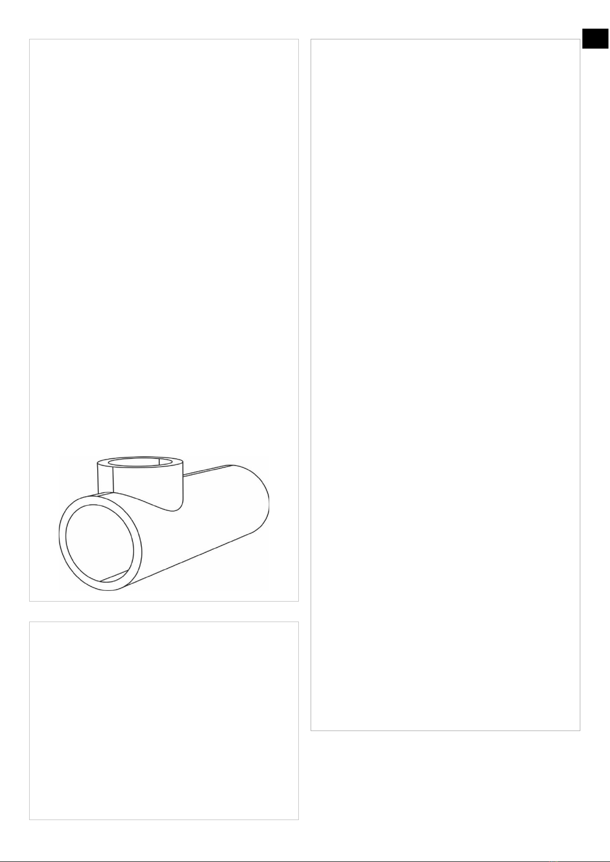
3. CAMPO DI UTILIZZO
La UP 125 è attrezzatura da cantiere che serve a realizzare derivazioni e collettori
forando e saldando per polifusione la conduttura con raccordi a di materiale
termoplastico quale PE, PP ed altri.
1
2
3
4
5
6
7
9
8
10
11
10

4
I
4. CRITERI DI SICUREZZA
L’utilizzo di questo prodotto è destinato esclusivamente a personale addestrato e
qualificato secondo le normative vigenti.
Adibire la macchina esclusivamente alla funzione descritta nel Capitolo Utilizzo e
secondo le istruzioni d’uso e manutenzione della saldatrice. Qualsiasi altro
impiego è da considerarsi improprio ed è vietato, poiché può causare lesioni agli
operatori, a terzi, e/o danni alla macchina o ad altri oggetti.
È assolutamente vietato rimuovere i dispositivi di sicurezza (interruttori,
microinterruttori, sigilli ecc.).
Sostituire prontamente qualsiasi componente usurato o danneggiato con ricambi
originali Ritmo.
Qualsiasi intervento di riparazione sulla macchina deve essere effettuato da
personale esperto e qualificato.
SEGNALI DI ALLERTA
Quando vedete questo segnale di allerta, leggete attentamente il
suo significato: LA TUA SICUREZZA È IN PERICOLO.
I segnali sono accompagnati da una delle seguenti parole:
PERICOLO, AVVERTIMENTO, e la CAUTELA.
Indica un imminente situazione di pericolo che se non
viene evitata darà luogo a morte o danno serio.
Indica una situazione potenzialmente pericolosa che se
non viene evitata potrebbe dare luogo a morte o danno serio.
Indica una situazione di pericolo che se non viene evitata
può dare luogo a danno minore o moderato.
In questo manuale è possibile incontrare altre due indicazioni: NOTA ed
IMPORTANTE.
NOTA: può attirare l’attenzione su un comportamento che potrebbe
danneggiare l’apparecchiatura . Può anche indicare una attenzione contro
pratiche pericolose.
IMPORTANTE: indica un suggerimento per come migliorare e/o
facilitare la metodologia di lavoro.
LEGGERE E CAPIRE
Non utilizzare questa apparecchiatura finché
non si abbia letto accuratamente e capito i
capitoli “CRITERI DI SICUREZZA” e ”ISTRUZIONI
D’USO” descritti nel presente manuale e negli
altri eventuali allegati ad esso. La propria
sicurezza e la sicurezza di altri dipendono
dall’uso appropriato della presente
attrezzatura. Seguire ed applicare le specifiche
normative relative all’uso
dell’apparecchiatura in funzione del luogo di
utilizzo.
Ritmo non può prevedere ogni possibile circostanza che potrebbe comportare
un potenziale pericolo. Gli avvertimenti in questo manuale e sulla macchina
non possono perciò garantire la sicurezza completa, pertanto bisogna
procedere all’utilizzo dell’apparecchiatura applicando un’opportuna
metodologia di lavoro che garantisca la propria sicurezza e quella degli altri.
Assicurarsi che l’uso e la manutenzione dell’apparecchiatura non creino
situazioni di pericolo.
PERICOLI DI NATURA ELETTRICA
Presente su:
•FORATRICE
•TERMOELEMENTO
Verificare che le caratteristiche elettriche della macchina corrispondano a
quelle della fonte di alimentazione. Il quadro da cantiere o il gruppo
elettrogeno ai quali si collega la macchina devono essere dotati di interruttore
differenziale ad alta sensibilità (I=30mA).
Non esporre la macchina alla pioggia o ad altri liquidi. Assicurarsi che le
protezioni isolanti (ad esempio i guanti) siano sempre perfettamente asciutte.
Non esporre i cavi ad agenti chimici o a sollecitazioni meccaniche (come
passaggio di veicoli e pedoni, contatto con oggetti taglienti, strattoni ecc.).
Scollegare la presa di alimentazione dalla rete elettrica a lavori terminati o
sospesi. Prima di utilizzare la macchina controllare l’integrità dei singoli
componenti, in particolare parti isolanti, cavi, passacavi e pressacavi.
Verificare mensilmente il corretto intervento dell’interruttore differenziale.
Effettuare una pulizia accurata della macchina al termine del suo utilizzo. Non
usare solventi, benzine, sostanze abrasive che potrebbero danneggiare le parti
isolanti.
Collegare a terra la macchina.
Verificare l’efficienza del collegamento a terra
L’eventuale cavo di prolunga deve essere a norma e adatto alla
potenza richiesta.
Luoghi ristretti o particolarmente umidi, cantieri circondati da
masse metalliche o acqua (ad esempio cantieri navali) richiedono l’utilizzo di
apparecchiature alimentate in SELV (bassissima tensione di sicurezza).
PERICOLI DI NATURA MECCANICA
Presente su:
COLONNA
MANDRINO
FRESA A TAZZA
Tenersi a distanza di sicurezza durante i movimenti della colonna.
PERICOLO DI
SCHIACCIAMENTO
PERICOLO DI
IMPIGLIAMENTO
PERICOLO DI
TAGLIO
PROIEZIONE
SCHEGGE
PERICOLI DI NATURA TERMICA
Presente su:
TERMOELEMENTO
Movimentare il termoelemento con cautela.
Pulire il termoelemento con cautela.
Non toccare il cordolo di saldatura e le zone limitrofe prima del completo
raffreddamento.
PERICOLO
DI USTIONI
USARE
GUANTI PROTETTIVI
Presente su:
TERMOELEMENTO
Non utilizzare la macchina in atmosfera esplosiva (per la
presenza di gas, vapori infiammabili ecc.).
Tenere fuori dal raggio d’azione del termoelemento
materiali deteriorabili con il calore o infiammabili (olii,
solventi, vernici ecc.).
PERICOLO DI
INCENDIO
CONTROLLO TEMPERATURA
Una errata impostazione della temperatura del
termoelemento può comportare un cattivo esito della
saldatura.
Verificare periodicamente con un termometro digitale
tarato che la temperatura delle superfici delle matrici
termoelemento sia corretta.

5
I
5. ISTRUZIONI D’USO
FISSAGGIO COLONNA
Fissare la colonna sul tubo centrando il punto di foratura.
Bloccare la prima maglia disponibile sul sistema di ancoraggio e fissarla con la
spina di sicurezza (1).
Tendere la catena attorno al tubo ruotando il manicotto (2).
FORATURA
1. Montare il mandrino adattatore sulla colonna:
2. Fissare la sega a tazza
3. Montare il trapano
non fissare il trapano sulla colonna.

6
I
Mantenere saldamente l’impugnatura del trapano, avviare la foratrice e forare
la condotta.
Spegnere la foratrice e rimuoverla dalla colonna.
RACCORDO
Inserire il mandrino del raccordo e fissare la catenella di sicurezza per evitarne
la caduta accidentale.
Tenere il collare della colonna sufficientemente allentato da permettere la
rotazione del mandrino senza basculare.
Posizionare le griffe in base alle dimensioni del raccordo.
Mantenere saldamente la
posizione del trapano

7
I
Bloccare il raccordo con le griffe.
Fissare la posizione delle griffe serrando la manopola.
POLIFUSORE
Montare le matrici adeguate fissandole in modo da garantire una buona
trasmissione del calore.
Attendere il raggiungimento della temperatura di lavoro.
SALDATURA
Inserire il polifusore tra raccordo e condotta e portare in contatto le zone da
saldare con le matrici.

8
I
Alcuni raccordi possono richiedere il preriscaldamento della zona di saldatura
sul tubo per un accoppiamento più omogeneo.
Posizionare il paletto di inserimento del polifusore tra il riscaldatore e il
raccordo attaccato al mandrino. Spingere il polifusore verso il tubo. Se
necessario, abbassare il mandrino per spingere la matrice contro il paletto.
Se necessario ruotare il mandrino per allineare il raccordo con la matrice del
polifusore.
Non utilizzare la maniglia inferiore per ruotare il mandrino, per non allentare le
griffe sul raccordo.
Al termine della fase di riscaldamento sollevare rapidamente il raccordo per
estrarre il polifusore.
9
I
Inserire il raccordo nella condotta e terminare la saldatura. Se necessario
ruotare il mandrino per migliorare l’allineamento.
Al termine del raffreddamento liberare la condotta ed il raccordo.
SALDATURA IN SERIE
Nell’esempio di seguito le derivazioni si trovano sullo stesso piano:
Le saldature possono essere effettuate anche su condotte con l’asse
longitudinale non in piano.
Utilizzare la squadretta con livella per segnare i centri dei fori.
Procedere con la foratura della condotta ed alla saldatura dei raccordi.
La squadretta consente di saldare anche raccordi sui fianchi utilizzando il lato
opposto alla figura in alto

10
I
6. MANUTENZIONE
Sconnettere foratrice e polifusore dalla rete
elettrica prima di eseguire qualsiasi intervento di manutenzione.
COLONNA
Mantenere le guide dei carrelli sempre pulite e oliate.
Non pulire le guide con stracci abrasivi o sostanze corrosive.
PASTIGLIA FRENO
Se il sostegno della colonna tende a scivolare verso il basso, fissare la pastiglia
del freno:
1. allentare il controdado e fissare la vite esagonale incassata al suo interno.
2. Fissare nuovamente il controdado
TERMOELEMENTO
Al termine di ogni saldatura pulire la superficie delle matrici di riscaldamento,
ancora alla temperatura di esercizio, con decapante adatto.
FORATRICE
Controllare lo stato di usura delle frese a tazza e del mandrino.
7. MALFUNZIONAMENTI
Sconnettere la macchina dalla rete elettrica prima di eseguire
qualsiasi intervento di manutenzione.
Consultare il manuale dedicato del polifusore.
Avvertenza
Le caratteristiche tecniche della macchina e i dati riportati nel presente manuale
possono subire variazioni senza preavviso a discrezione del costruttore.
È vietata la riproduzione, anche parziale e sotto qualsiasi forma, di questo
documento.
Le parti di ricambio e la documentazione tecnica è disponibile anche online:
www.ritmo.cloud.
Supporto in caso di problemi:
S.p.A.
via A. Volta, 35/37 - Z.I. Selve
35037 BRESSEO DI TEOLO (PD)
ITALIA
Tel. +39.049.990.1888
Fax +39.049.990.1993
service@ritmo.it
Smaltimento
Non smaltire con i rifiuti domestici!
Aggiunga l’apparecchio fuori uso ad una raccolta separata affinché possa
essere riutilizzato in rispetto all’ambiente.

11
EN
1. INTRODUCTION
Dear Customer,
thank you for choosing our products.
This manual has been written to illustrate the characteristics and the appropriate
and safe use of the product that you have acquired. You will find all the necessary
information and advice for the correct and safe use of the equipment by
specialized personnel. We recommend reading all its parts carefully before using
the equipment and keeping it for future reference and future users.
We are sure that it will be easy for you to become familiar with your new
equipment and that you can use it for a long time and with great satisfaction.
Best regards,
Ritmo S.p.A.
2. TECHNICAL FEATURES
Net Weight [Kg]:
16
Transport box l x l x h [mm]
420x580x177
Transport box weight [Kg]
7
Main-pipe diameters [mm]:
Ø 63 ÷ Ø 630
Branch pipe diameters [mm]:
Ø 32 ÷ Ø 125
1
Fitting chuck
2
Drill press
3
Framing bracket with level (630mm bracket on demand))
4
Locking chain
5
Chain extension
6
Heater insertion rod
ADAPTER FOR DRILLS
7
Adapter
EQUIPMENT ON DEMAND
8
Holesaw driver (all sizes)
9
Hole saw
SADDLE DIES AND HOT IRON
10
Dies
11
Iron for heat fusion
3. APPLICATIONS
UP 125 is construction equipment that serves to bore a main pipe made of PP, PE,
other thermoplastics and weld by polyfusion the outlet-sockets of branch pipes.
1
2
3
4
5
6
7
9
8
10
11
10

12
EN
4. SAFETY CRITERIA
This equipment should only be used in accordance with the instructions
described in this manual. Any other use is forbidden, since it may cause damages
to persons, machine or other objects
The usage of this product is intended exclusively to qualified operators according
to the standards in force.
Use this machine only for the purposes described on chapter “Fields of
Application” and according to its operator’s manual.
Replace defective or worn-out parts only with Ritmo genuine spare parts.
Any intervention or repair on this product has to be carried out by qualified
operators.
SAFETY ALERTS
This hazard alert sign appears in this manual, when you see this
sign, carefully read what it says: YOUR SAFETY IS AT STAKE.
You will see the hazard alert sign with these words:
DANGER, WARNING, and CAUTION.
Indicates an imminently hazardous situation which, if not
avoided, will result in death or serious injury.
Indicates a potentially hazardous situation which, if not
avoided, could result in death or serious injury.
Indicates a hazardous situation which, if not avoided, may
result in minor or moderate injury.
In this manual you should look for two other words: NOTICE and IMPORTANT.
NOTICE: can keep you from doing something that might damage the machine
or someone's property. It may also be used to alert against unsafe practices.
IMPORTANT: can help you do a better job or make your job easier in some
way.
READ AND UNDERSTAND
Do not operate this equipment until you have
carefully read, and understand the "Safety" and
"Operation" sections of this manual, and all
other equipment manuals that will be used with
it. Your safety and the safety of others depends
upon care and judgment in the operation of this
equipment.
Follow all applicable federal, state, local, and
industry specific regulations.
Ritmo Manufacturing, cannot anticipate every possible circumstance that
might involve a potential hazard. The warnings in this manual and on the
machine are therefore not all inclusive. You must satisfy yourself that a
procedure, tool, work method, or operating technique is safe for you and
others. You should also ensure that the machine will not be damaged or made
unsafe by the method of operation or maintenance you choose.
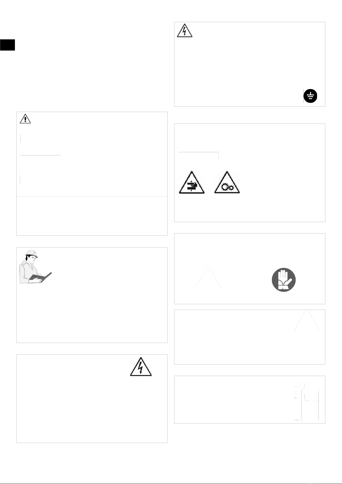
ELECTRIC HAZARDS
Parts involved:
•HOT IRON
•DRILLING MACHINE
Check that the electric features of the machine correspond with those of the
power source.
The on-site board or the power unit to which the machine is connected must
be equipped with a high-sensitivity differential switch (I=30mA).
Do not expose the machine to rain or to any other liquids.
Make sure that all the accessories, implements, etc. used for protection (e.g.
gauntlets) are always completely dry.
Do not expose the cables to chemical agents, mechanical strain or general
hazards such as the passage of vehicles or passers-by, contact with sharp
objects, pulls, etc.
Unplug the machine when no longer in use or for temporary interruptions.
Before using the machine check that each single part is in perfect working
order, especially the insulating components like cables, cable leads and
pressers. Once monthly, check that the differential switch is in perfect
working order.
Clean the machine thoroughly at the end of each session. Do not use solvents,
petrol or any abrasive substances which might damage the
insulating parts.
Connect the machine to earth.
Check that the earth connection is operative.
If it becomes necessary to use an extension, the cable must
comply with the regulations in force and be suitable for the
power required.
SELV-powered equipment (extremely low safety voltage) is
required in narrow spaces, particularly damp places, sites surrounded by
metal structures or water (e.g. shipyards).
MECHANICAL HAZARDS
Parts involved:
DRILL PRESS
FITTING CHUCK
HOLE SAW
Keep at a safe distance while the carriage is in motion.
CRUSHING
HAZARD
CATCHING
ENTANGLING
HAZARD
CUTTING
HAZARD
SPLINTERING
HAZARD
HAZARD RELATED TO TEMPERATURE
Parts involved:
•HEATING PLATE
Handle the heating plate with caution.
Extreme caution should be taken when cleaning the heating plate.
Do not touch the welded bead nor the surrounding areas until they have
cooled down completely.
BURNING
HAZARD
USE PROTECTIVE
GLOVES
Parts involved:
•HEATING PLATE
Do not use the machine if the area is at risk of explosion
due to the presence of flammable gases etc.
Keep outside the range of the heating plate any
flammable materials or those which may deteriorate in
the
heat (e.g. oils, solvents, paint, etc.).
FIRE HAZARD
TEMPERATURE CHECK
Incorrect setting of the thermoelement temperature can
lead to a bad welding result.
Periodically check with a calibrated digital thermometer
that the temperature of the thermoelement surfaces is
correct.

13
EN
5. WORKING INSTRUCTIONS
DRILL-PRESS SECURING
Find the bore position and secure the drill press on the top of the main pipe.
Block the first available link of the chain and secure it with the split pin (1).
Tension the chain around the pipe by turning the sleeve (2).
BORE
1. Mount the adapter on the press
2. Secure the hole-saw.
3. Mount the drill on the drill-press.
do not secure the drill to the press directly

14
EN
Firmly hold the drill, start it and bore the hole.
Switch off the drill and remove it from the drill-press.
OUTLET-SOCKET FITTING
Insert the chuck of the fitting and secure the safety chain to prevent it from
falling accidentally.
Keep the column collar loose enough to allow the chuck to rotate without
slipping off.
Position the jaws according to the size of the fitting.
Firmly hold the drill in its position

15
EN
Close the jaws to firmly hold the fitting.
Tighten the knob to secure the jaws’ position.
HOT IRON
Mount the dies suitable to the parts to be welded. The dies must couple with
both main pipe and fitting.
The contact surfaces must ensure a good heat transmission.
Wait till the dies have reached the working temperature.
WELDING
Insert the iron between the fitting and the main pipe, then bring the areas to
be welded into contact with the dies.

16
EN
Some fittings may require preheating of the welding area on the pipe for a more
homogeneous coupling.
Place the Heater insertion rod between the hot iron and the fitting secured to
the chuck. Push the iron towards the pipe. If necessary, lower the chuck to push
the spigot into the pipe bore.
If necessary, turn the chuck to align the fitting with the die.
Do not use the lower handle to turn the chuck, in order not to loosen the jaws
on the fitting.
At the end of the heating phase, quickly lift the fitting to extract the iron.

17
EN
Insert the fitting into the main pipe and carry out the welding. If necessary,
turn the spindle to improve alignment.
At the end of the cooling, loose both pipe and fitting.
CONTRUCTION OF MULTI-BRANCH PIPE LINE
In the example below the outlet-sockets are on the same plane:
The welds can also be carried out on pipes with the longitudinal axis not
level.
Use the framing bracket to align the bores to be made on the same plane.
Proceed with drilling the main pipe and welding the fittings.
The framing-bracket also allows you to weld fittings on the pipe-sides as
depicted below:
18
EN
6. MAINTENANCE
Unplug the drill and the heater from the power source before
performing any maintenance intervention.
DRILL PRESS
Keep the drill-press column clean and lubricated.
Do not clean the guide with abrasive rags or corrosive substances.
BRAKE PAD
If the column press tends to slide down, tighten the brae-pad:
1. loosen the lock nut and fix the hexagonal screw recessed inside it.
2. Re-tighten the lock nut
HOT IRON
At the end of each welding, clean the surface of the dies, still at
the operating temperature, with a suitable cleaning flux.
DRILLING MACHINE
Check the wear of the hole saws and chuck.
7. TROUBLESHOOTING
Unplug the drill and the heater from the power source before
performing any maintenance intervention.
Read the hot-iron handbook
Notice
The technical characteristics of the machine and the data shown in this manual
may undergo variations without notice at the discretion of the manufacturer.
It is strictly prohibited to reproduce this document or part of it in any form
whatsoever.
Full spare part list and technical documents available online at www.ritmo.cloud.
Help in the event of problems:
S.p.A.
via A. Volta, 35/37 - Z.I. Selve
35037 BRESSEO DI TEOLO (PD)
ITALY
Tel. +39.049.990.1888
Fax +39.049.990.1993
service@ritmo.it
Disposal Do not dispose of in the household trash. Add the device that is no
longer able to be used to a separate collection for the purpose of
environmentally friendly recycling.

19
D
1. EINLEITUNG
Sehr geehrter Kunde,
Wir danken Ihnen, eine Maschine der Ritmo-Produktion gewählt zu haben.
In diesem Handbuch werden die Funktionen und die Verwendung Ihres neuen
Produkts erläutert. Es enthält sämtliche Informationen und Hinweise für den
sachgerechten und sicheren Einsatz des Geräts durch fachlich geschultes Personal.
Das Handbuch muss vor dem Gebrauch der Maschine vollständig gelesen werden
und ist für zukünftigen Bedarf oder andere Benutzer sorgfältig mit der Maschine
zusammen zu verwahren. Wir sind überzeugt, dass Sie mit Ihrem neuen Gerät
schnell vertraut sein werden und dass es Ihnen auch für lange Zeit beste Dienste
leisten wird.
Mit freundlichen Grüßen,
Ritmo S.p.A.
2. TECHNISCHE EIGENSCHAFTEN
STANDARD AUSFÜHRUNG
Gesamtgewicht der Maschine [Kg]:
16
Abmessungen Transportkiste l x l x h [mm]
420x580x177
Gewicht Transportkiste [Kg]
7
Hauptrohrdurchmesser [mm]:
Ø 63 ÷ Ø 630
Durchmesser Abgang [mm]:
Ø 32 ÷ Ø 125
1
Spindel mit Backen zur Befestigung der Einschweißsattel
2
Bohrmaschinenständer
3
Rahmenhalterung mit Wasserwaage (630 mm auf Nachfrage)
4
Verriegelungskette
5
Kettenverlängerung
6
Schweißwerkzeug-Einführstange
ADAPTER FÜR BOHRER
7
Spindeladapter
ZUBEHÖR AUF ANFRAGE
BOHRMASCHINE UND LOCHSÄGEN
Netzspannung:
220÷230 V, 50÷60 Hz einphasig
120 V 60 Hz einphasig
Leistungsaufnahme Nennwert [W]:
750W
Gesamtgewicht [kg]:
3
Geräuschpegel
LwA = 77 dBA
8
Mitnehmer (alle Lochsägen)
9
Lochsägen
SCHWEISSWERKZEUG UND MUFFENSCHWEISSGERÄTS
10
Schweißwerkzeug
11
Muffenschweißgerät
3. ANWENDUNGSBEREICH
UP 125 ist eine Maschine zum Bohren eines Hauptrohrs aus PP, PE und anderen
Thermoplasten und zum Schweißen von Einschweißsätteln.
1
2
3
4
5
6
7
9
8
10
11
10
20
D
4. SICHERHEITSKRITERIEN
Die Verwendung dieses Produkts ist nur für Personal bestimmt, das gemäß den
geltenden Vorschriften geschult und qualifiziert ist.
Verwenden Sie das Gerät ausschließlich für die im Kapitel über die Verwendung
und gemäß den Anweisungen zur Verwendung und Wartung des Schweißgeräts
beschriebene Funktion. Jede andere Verwendung ist als unsachgemäß zu
betrachten und ist verboten, da sie zu Verletzungen von Bedienern, Dritten
und/oder Schäden an der Maschine oder anderen Gegenständen führen kann.
Es ist strengstens verboten, die Sicherheitsvorrichtungen (Schalter,
Mikroschalter, Dichtungen usw.) zu entfernen.
Ersetzen Sie verschlissene oder beschädigte Komponenten sofort durch Original-
Ritmo-Ersatzteile.
Alle Reparaturarbeiten an der Maschine müssen von fachkundigem und
qualifiziertem Personal durchgeführt werden.
ALARMSIGNALE
Wenn Sie dieses Warnzeichen sehen, lesen Sie dessen Bedeutung
sorgfältig durch: IHRE SICHERHEIT IST IN GEFAHR.
Die Signale werden von einem der folgenden Wörter begleitet:
GEFAHR, WARNUNG und VORSICHT.
Weist auf eine unmittelbar bevorstehende
Gefahrensituation hin, die zum Tod oder zu ernsthaften Schäden führt, wenn
sie nicht vermieden wird.
Weist auf eine potenziell gefährliche Situation hin, die
zum Tod oder zu ernsthaften Schäden führen kann, wenn sie nicht vermieden
wird.
Weist auf eine gefährliche Situation hin, die zu
geringfügigen oder mäßigen Schäden führen kann, wenn sie nicht vermieden
wird.
In diesem Handbuch finden Sie zwei weitere Angaben: HINWEIS und
WICHTIG.
HINWEIS: Dies kann auf Verhaltensweisen aufmerksam machen, die das
Gerät beschädigen können. Dies kann auch auf Vorsicht vor gefährlichen
Praktiken hinweisen.
WICHTIG: Weist auf einen Vorschlag zur Verbesserung und / oder
Erleichterung der Arbeitsmethode hin.
LESEN UND VERSTEHEN
Verwenden Sie dieses Gerät erst, wenn Sie die in diesem
Handbuch und in anderen Anhängen beschriebenen
Kapitel Sicherheitskriterien und Gebrauchsanweisung
sorgfältig gelesen und verstanden haben. Ihre eigene
Sicherheit und die Sicherheit anderer hängt von der
ordnungsgemäßen Verwendung dieser Ausrüstung ab.
Die spezifischen Vorschriften für die Verwendung des
Geräts sind entsprechend dem Verwendungsort zu befolgen und
anzuwenden.
Ritmo kann nicht alle eventuell möglichen Umstände vorhersehen, die eine
potenzielle Gefahr darstellen könnten. Die Warnhinweise in diesem
Handbuch und auf der Maschine können daher keine vollständige Sicherheit
garantieren. Daher ist es erforderlich, dass bei der Verwendung des Geräts
eine geeignete Arbeitsmethode angewendet wird, die die eigene Sicherheit
und die anderer gewährleistet. Stellen Sie sicher, dass bei Verwendung und
Wartung der Geräte keine gefährlichen Situationen entstehen.
ELEKTRISCHE GEFÄHRDUNGEN
Betrifft:
•HEIZELEMENT
•BOHRMASCHINE
Überprüfen Sie, ob die elektrischen Eigenschaften der Maschine denen der
Stromquelle entsprechen. Der Schaltkasten der Baustelle oder das
Stromaggregat, an das die Maschine angeschlossen ist, muss mit einem
hochempfindlichen Differenzschalter (I= 30mA) ausgestattet sein.
Die Maschine darf nicht Regen oder anderen Flüssigkeiten ausgesetzt
werden. Stellen Sie sicher, dass die isolierenden Schutzvorrichtungen (z. B.
Handschuhe) immer perfekt trocken sind. Setzen Sie die Kabel keinen
chemischen Stoffen oder mechanischen Belastungen aus (z. B. dem
Überfahren durch Fahrzeuge das Betreten durch Fußgänger, dem Kontakt mit
scharfen Gegenständen, Stößen usw.). Ziehen Sie den Netzstecker aus der
Steckdose, wenn die Arbeit beendet ist oder unterbrochen wird.
Jedes Verlängerungskabel muss den Anforderungen entsprechen
und für die erforderliche Leistung geeignet sein.
Beengte oder besonders feuchte Umgebungen, Baustellen, die
von Metallmassen oder Wasser umgeben sind (z. B. Werften), erfordern die
Verwendung von Geräten, die mit SELV betrieben werden (sehr niedrige
Sicherheitsspannung).
Überprüfen Sie vor dem Gebrauch der Maschine die Unversehrtheit der
einzelnen Komponenten, insbesondere der Isolierteile, Kabel,
Kabelverschraubungen und Kabelzuführungen.
Überprüfen Sie monatlich den korrekten Eingriff des Differentialschalters.
Führen Sie am Ende des Gebrauchs eine gründliche Reinigung der Maschine
durch. Verwenden Sie keine Lösungsmittel, Benzine oder
Schleifmittel, die die isolierenden Teile beschädigen könnten.
Erden Sie die Maschine.
Überprüfen Sie die Effizienz der Erdung
MECHANISCHE GEFÄHRDUNGEN
Betrifft:
BOHRMASCHINENSTÄNDER
SPINDEL
LOCHSÄGEN
Halten Sie beim Bewegen des beweglichen Schlittens einen Sicherheitsabstand
ein.
GEFÄHRDUNG
DURCH
QUETSCHEN
GEFÄHRDUNG
DURCH
ERFASSEN
ODER
AUFWICKELN
SCHNITTGEFAHR
SPLITTERGEFAHR
THERMISCHE GEFAHREN
Betrifft:
WÄRMEELEMENT
Bewegen Sie das Wärmeelement vorsichtig.
Reinigen Sie das Wärmeelement sorgfältig.
Berühren Sie den Schweißstab und seine Umgebung nicht, bevor Sie
vollständig abgekühlt sind.
VERBRENNUNGS-
GEFAHR
SCHUTZ-HANDSCHUHE
VERWENDEN
Betrifft:
HEIZELEMENT
Verwenden Sie die Maschine nicht in
explosionsgefährdeten Bereichen (aufgrund von
brennbaren Gasen, Dämpfen usw.).
Halten Sie leicht verflüchtigende oder brennbare
Materialien (Öle, Lösungsmittel, Farben usw.) außerhalb
des Bereichs des Wärmeelements.
BRAND-
GEFAHR
TEMPERATURKONTROLLE
Eine falsche Einstellung der Temperatur des
Wärmeelements kann zu einem schlechten
Schweißergebnis führen.
Überprüfen Sie regelmäßig mit einemkalibrierten digitalen
Thermometer, ob die Temperatur der Oberflächen der
Wärmeelementmatrizen korrekt ist.
Table of contents
Languages:
Other Ritmo Welding System manuals


Popular Welding System manuals by other brands


ESAB
ESAB Aristo YardFeed 2000 instruction manual

Lincoln Electric
Lincoln Electric Pro-Cut 55 Technical specifications

GYS
GYS CONNECT 5 quick start guide

Miller Electric
Miller Electric MT-24-12-1 owner's manual

EWM
EWM Drive XQ IC D200 operating instructions

Lincoln Electric
Lincoln Electric EAGLE SVM192-A Service manual