manuals.online logo
Brands
  1. Home
  2. •
  3. Brands
  4. •
  5. Rittal
  6. •
  7. Industrial Equipment
  8. •
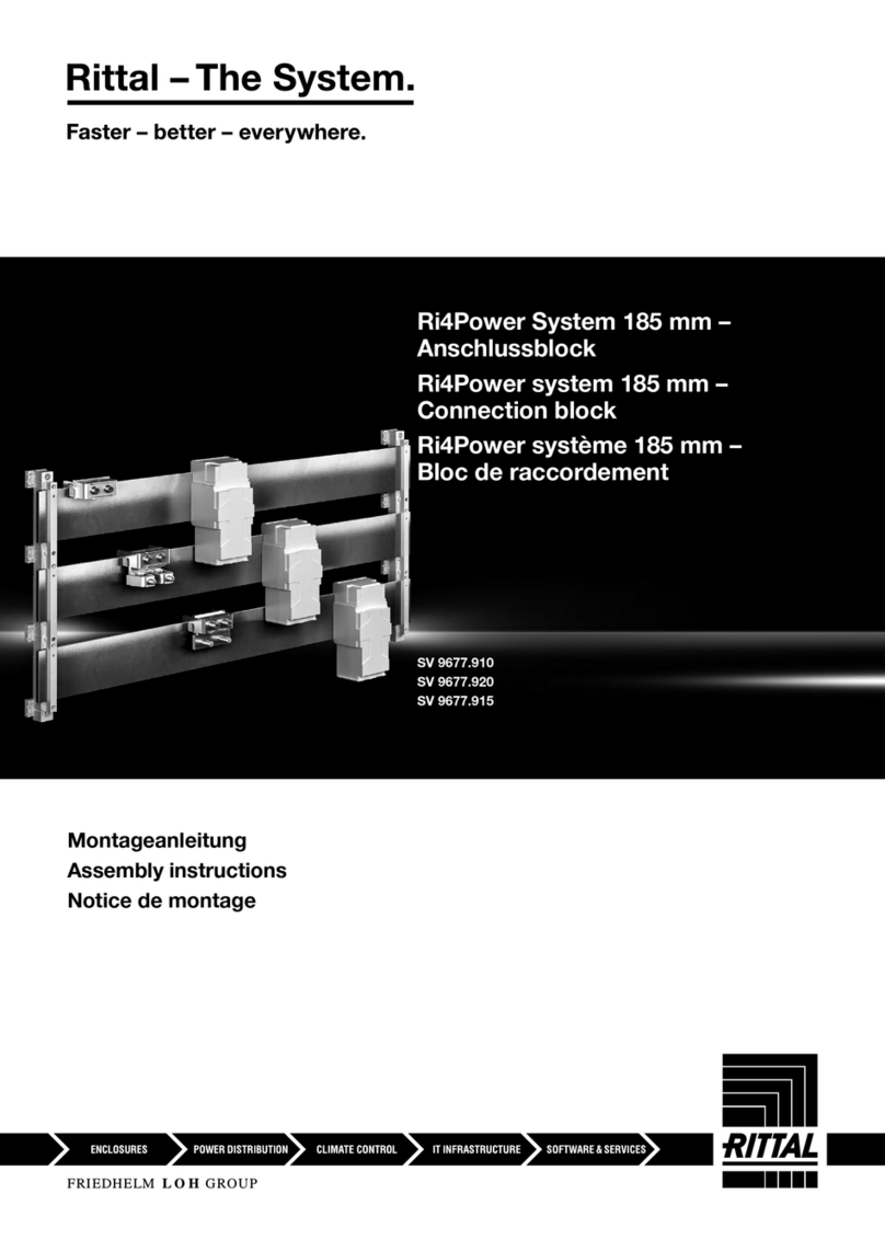
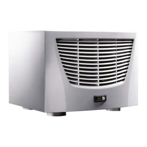
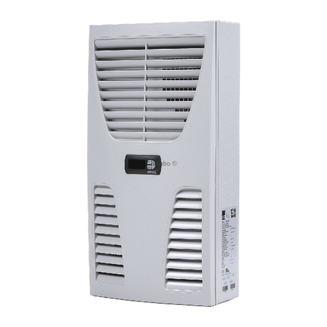
  9. Rittal Top Therm SK 3126.4 Series User manual

Rittal Top Therm SK 3126.4 Series User manual

Montageanleitung
Assembly instructions
Notice de montage
Montage-instructie
Montageanvisning
Istruzioni di montaggio
Instrucciones de montaje
R
Luft/Luft-
Wärmetauscher
Scambiatori di calore
aria/aria
Wärmeväxelare
luft/luft
Warmtewisselaars
lucht/lucht
Echangeurs
thermiques air/air
Heat exchangers
air/air
Intercambiadores
de calor aire/aire
SK 3126.4xx
SK 3128.4xx
SK 3129.4xx
SK 3130.4xx
ma_titel_sk_3126.fm Seite 1 Freitag, 23. Januar 2009 12:16 12
2 Montageanleitung Rittal Luft/Luft-Wärmetauscher
50
7.5
30
7.5
27.5
M6
M6
M6
70
140
70
27.5 250
400
327
950
36.5
180
180
280
255
920
385
345
20
160
30
50
327
370
30
365
160
10
920
190.5
619
127
198
175
175
39.5
39.5
28
402
250
23
999
250
750
953
250
448
402
92.5
112.5
47.5
27.5
140
250
70
27.5
47.5
92.5
112.5
Ø 8 (7 x)
1
Ø 40 (2 x)
Ø 9.5 (8 x)
650
1.5
17.5
22.5
(66.5)
8
57
254
75.5
282
21.5
23
699
60
1
22.5
Ø 8 (8 x)
74
60
27.5
280
244
600
611
255
Ø 7 (4 x)
127
==
Ø 8 (8 x)
=
=
520
653
328
650
362.5
105
254
118
105
215
254
107
624
37.5
89.5
109.5
60
60
84.5
104.5
127
42.5
22.5
7.5
M6
M6
30
7.5
50
Montageausschnitte/Mounting cut-outs
SK 3126.4xx
SK 3128.4xx
Anbau/External Installation Einbau mit Verstellrahmen/Internal Installation with adjustable frame
Einbau/Internal Installation
Verstellmöglichkeiten/Adjustment options
Anbau/External Installation Einbau mit Verstellrahmen/Internal Installation with adjustable frame
Einbau/Internal Installation
Verstellmöglichkeiten/Adjustment options
Moosgummidichtung EPDM, schwarz 12 mm,
als geschlossene umlaufende Runddichtschnur
Microcellular rubber seal EPDM, black 12 mm,
as solid all-round rubber seal
1
Moosgummidichtung EPDM, schwarz 12 mm,
als geschlossene umlaufende Runddichtschnur
Microcellular rubber seal EPDM, black 12 mm,
as solid all-round rubber seal
1
ma_innen_sk_3126.fm Seite 2 Freitag, 23. Januar 2009 11:56 11
Montageanleitung Rittal Luft/Luft-Wärmetauscher 3
25 250
400
327
950
25
210
210
280
255
920
385
345
35
145
35
50
327
Ø 40 (2 x)
Ø 9.5 (8 x)
150
70
402
250
23
999
250
750
953
250
448
402
370
30
365
160
10
920
190.5
619
127
215
180
180
37
37
19.5
50
7.5
30
7.5
27.5
M6
M6
M6
70
1
250
27.5
47.5
102.5
122.5
92.5
112.5
57.5
37.5
150
70
400 150
1580
402
1582
448
250
1480
1628
200
280260260
280200
320
113
205
205
1558
924.5
97.5
67.5
370
370
400
965
1580
367
210
210
65
395
280
380
275 875
340
260
320
1530
215
62.5
200
70
Ø 40 (1 x)
Ø 11 (8 x)
Ø 11 (6 x)
Ø 8 (2 x)
70
50
7.5
30
7.5
27.5
M6
M6
M6
1
250
27.5
47.5
102.5
122.5
92.5
112.5
57.5
47.5
150
70
Montageausschnitte/Mounting cut-outs
SK 3129.4xx
SK 3130.4xx
Anbau/External Installation Einbau mit Verstellrahmen/Internal Installation with adjustable frame
Einbau/Internal Installation
Verstellmöglichkeiten/Adjustment options
Anbau/External Installation Einbau mit Verstellrahmen/Internal Installation with adjustable frame
Einbau/Internal Installation
Verstellmöglichkeiten/Adjustment options
Moosgummidichtung EPDM, schwarz 12 mm,
als geschlossene umlaufende Runddichtschnur
Microcellular rubber seal EPDM, black 12 mm,
as solid all-round rubber seal
1
Moosgummidichtung EPDM, schwarz 12 mm,
als geschlossene umlaufende Runddichtschnur
Microcellular rubber seal EPDM, black 12 mm,
as solid all-round rubber seal
1
ma_innen_sk_3126.fm Seite 3 Freitag, 23. Januar 2009 11:56 11
4 Montageanleitung Rittal Luft/Luft-Wärmetauscher
Inhaltsverzeichnis
1. Anwendung
2. Technische Daten
3. Montage Wandgeräte
4. Sicherheitshinweise
5. Elektrischer Anschluss
6. Inbetriebnahme
7. Technische Information
8. Wartung
9. Lieferumfang und Garantie
1. Anwendung
Luft/Luft-Wärmetauscher (LLWT) sind entwickelt und konstruiert,
um Verlustwärme aus Schaltschränken abzuführen bzw. die
Schrankinnenluft zu kühlen und so temperaturempfindliche Bau-
teile zu schützen. Besonders geeignet sind LLWT bei aggressiver
Umgebungsluft, da diese durch die zwei getrennten Luftkreisläufe
nicht ins Schaltschrankinnere gelangen kann. Voraussetzung für
den Einsatz ist eine Umgebungstemperatur, die unter der ge-
wünschten Schaltschrankinnentemperatur liegt.
2. Technische Daten
(siehe Seite 7)
3. Montage Wandgeräte
Das Wandgerät kann serienmäßig wahlweise an- oder eingebaut
werden. Ausschnitte und Bohrungen entsprechend an der
Montageebene ausschneiden.
3.1 Montage Anbau
Beiliegende Dichtungen ablängen und auf das Gerät entspre-
chend kleben, Gewindestifte an die Geräterückseite in die Blind-
muttern eindrehen. Anschließend ist das Gerät mittels Scheiben
und Muttern zu befestigen.
3.2 Montage Einbau
Zunächst sind die Lamellengitter und der Gürtel abzunehmen.
Beiliegende Dichtungen ablängen und auf das Gerät entspre-
chend kleben. Muttern und Scheiben lösen, anschließend Gerät
mit den Scheiben und Muttern am Schrank befestigen.
4. Sicherheitshinweise
Die nachfolgenden Sicherheitshinweise sind vollständig für den
fachgerechten Einsatz der Geräte zu beachten:
●
Um ein Kippen des Schaltschrankes mit montiertem LLWT zu
verhindern, muss dieser unbedingt am Boden verschraubt
werden.
●
Zum problemlosen Öffnen und Schließen der Schaltschranktür
ist eine Tür-Auflaufrolle zu verwenden.
●
Ein Schranktransport mit angebautem LLWT darf ausschließlich
unter Verwendung einer zusätzlichen Transportsicherung
zwecks Abstützung des LLWT durchgeführt werden.
Vor der Montage ist zu beachten, dass
●
der Aufstellungsort des Schaltschrankes und damit die Anord-
nung des LLWT so gewählt wird, dass eine gute Be- und Ent-
lüftung gewährleistet ist;
●
der Aufstellungsort frei von starkem Schmutz und Feuchtigkeit
ist;
●
sich der Ausschnitt für die Luftansaugung möglichst im oberen
Bereich des Schaltschrankes befinden sollte;
●
die auf dem Typenschild des Gerätes angegebenen Netzan-
schlussdaten gewährleistet sind;
●
die Umgebungstemperatur nicht höher als +55°C ist;
●
die Verpackung keine Beschädigungen aufweist.
Verpackungsschaden kann die Ursache für einen nach-
folgenden Funktionsausfall sein;
●
der Schaltschrank allseitig abgedichtet ist (IP 54);
●
der Abstand der Geräte zueinander bzw. zur Wand mindestens
200 mm beträgt;
●
Luftein- und -austritt innen nicht verbaut sind;
●
Geräte nur waagerecht entsprechend der vorgegebenen Lage
angebaut werden;
●
der elektrische Anschluss und eventuelle Reparatur nur vom
autorisierten Fachpersonal durchgeführt werden darf.
Nur Originalersatzteile verwenden!
●
die Verlustleistung der im Schaltschrank installierten Kompo-
nenten das jeweilige Leistungsvermögen der LLWT nicht über-
schreiten darf;
●
kundenseitig keine Modifikationen am LLWT vorgenommen
werden dürfen.
5. Elektrischer Anschluss
Die Anschlussspannung und -frequenz muss den auf dem Typen-
schild angegebenen Nennwerten entsprechen.
Der LLWT muss über eine allpolige Trennvorrichtung an das Netz
angeschlossen werden, die mindestens 3 mm Kontaktöffnung im
ausgeschalteten Zustand gewährleistet.
Als Leitungsschutz ist die auf dem Typenschild angegebene Vor-
sicherung vorzusehen. Bei der Installation geltende Vorschriften
beachten!
6. Inbetriebnahme
Nach erfolgter Gerätemontage kann der elektrische Anschluss er-
folgen.
7. Technische Information
7.1 Kondensatablauf
Beim Betrieb der LLWT in Umgebungen, in denen z. B. Öl-/Farb-
nebel oder hohe Luftfeuchtigkeiten vorhanden sind, können sich
diese im Außenkreislauf des Gerätes niederschlagen. Zum Ablas-
sen aus dem Gehäuse kann einfach der Plastikstopfen am Gerä-
teboden entfernt werden.
7.2 Allgemeines
Lagertemperatur: Die LLWT dürfen während der Lagerung Tem-
peraturen über +70°C nicht ausgesetzt werden.
Die Entsorgung kann im Rittal Werk durchgeführt werden.
Technische Änderungen vorbehalten.
8. Wartung
Die eingebauten wartungsfreien Ventilatoren sind kugelgelagert,
feuchtigkeits- und staubgeschützt. Die Lebenserwartung beträgt
mindestens 30.000 Betriebsstunden. Der LLWT ist damit weitge-
hend wartungsfrei. Lediglich die Lamellen der Wärmetauscher-
kassette müssen eventuell von Zeit zu Zeit gereinigt werden.
Dies kann
a) durch Ausblasen mit Pressluft bei trockenem Staub
b) durch Auswaschen mit Waschlauge (max. 75°C) bei Fett- und
Ölrückständen (vor Anbau allseitig abtrocknen!) geschehen.
Zum Reinigen kann die Wärmetauscherkassette durch Lösen des
Exzenterhebels bzw. Lösen von zwei Halteschrauben aus dem
Gehäuse herausgenommen werden. Vorher sind die Frontplatten
abzuschrauben.
Achtung:
Vor Wartungsarbeiten ist der LLWT einspeisungsseitig span-
nungsfrei zu schalten.
9. Lieferumfang und Garantie
1 LLWT anschlussfertig
1 Bohrschablone
1 Dichtband
1 Montage- und Betriebsanleitung
Garantie:
Auf dieses Gerät gewähren wir 2 Jahre Garantie bei fachgerech-
ter Anwendung (s. a. Sicherheitshinweise unter Punkt 4.) vom
Tage der Lieferung an. Innerhalb dieses Zeitraumes wird das ein-
geschickte Gerät im Werk kostenlos repariert oder ausgetauscht.
Der LLWT ist ausschließlich zum Kühlen von Schaltschränken zu
verwenden. Bei unsachgemäßer Anwendung oder Anschließung
erlischt die Gewährleistung des Herstellers. Für die in solchem
Fall entstandenen Schäden wird nicht gehaftet.
Hinweise
DE
ma_innen_sk_3126.fm Seite 4 Freitag, 23. Januar 2009 11:56 11
Montageanleitung Rittal Luft/Luft-Wärmetauscher 5
Notes
GB
Table of Contents
1. Application
2. Technical data
3. Wall mounting
4. Safety notices
5. Electrical connection
6. Commencing operation
7. Technical information
8. Maintenance
9. Scope of supply and guarantee
1. Application
Air/air heat exchangers are designed and built to
dissipate heat from
enclosures by cooling the air
inside the enclosure and protecting
temperature-
sensitive components. The LLWT is particularly sui-
ted for operation in surroundings with an aggressive airflow be-
cause the two separate air circulation circuits prevent it from en-
tering the inside of the enclosure. A utilisation condition here is
that the surrounding temperature must be lower than the planned
enclosure temperature.
2. Technical data
(see page 7)
3. Wall mounting
The standard wall unit can chosen for internal or
external wall
mounting and the mounting level cut-outs and holes must be made.
3.1 External mounting
Cut the enclosed seals to the required length and attach to the
unit. Screw tapped pins into the blind nuts on the rear of the unit.
The unit is then to be secured using washers and nuts.
3.2 Internal mounting
First remove the lamella grid and belt. Cut the enclosed seals
to the required length and attach to the unit. Loosen the nuts and
washers, then fasten the unit to the enclosure with the washers
and nuts.
4. Safety notices
The following safety notices are to be observed in their entirety
with regard to the correct utilisation of the unit:
●
To prevent the enclosure with the air/air heat exchanger fitted
tipping over, it is essential that this be bolted to the floor.
●
A roller door is to be used to ensure problem-free opening and
closing of the enclosure door.
●
A transportable enclosure with built-in air/air heat exchanger
may only be produced if an additional transport anchorage to
support the heat exchanger is used.
Prior to mounting, ensure that:
●
The site for the enclosure, and hence the arrangement of the
air/air heat exchanger, is selected so as to ensure good venti-
lation;
●
The location is free from excessive dirt and moisture;
●
The cutout for air extraction is located in the upper area of the
enclosure;
●
The mains connection ratings, as stated on the rating plate, are
available;
●
The ambient temperature does not exceed +55°C;
●
The packing must not show signs of damage. Any damage to
the pakkaging may be the cause of subsequent malfunctions;
●
The enclosure is sealed on all sides (IP 54);
●
The separation of the units from one another and from the wall
should not be less than 200 mm;
●
Air inlet and outlet are not obstructed on the inside of the enclo-
sure;
●
The unit must be mounted so that it is horizontal in accordance
with the planned position;
●
Only authorised personnel are permitted to make the electrical
connections and repairs. Use only original replacement parts!
●
The heat loss from the components installed in the enclosure
must never exceed the respective power capability of the
LLWT;
●
The customer must not modify the air/air heat exchanger unit in
any way.
5. Electrical connection
The connected voltage and frequency must correspond to the
values stated on the rating plate.
The air/air heat exchanger must be connected to the mains via an
all-pin isolating device which ensures at least 3 mm contact ope-
ning when switched off.
Line protection should be provided by means of the fusing speci-
fied on the rating plate. Observe the relevant regulations during
installation!
6. Commencing operation
Following the completion of mounting, electrical connection can
be made.
7. Technical information
7.1 Condensation discharge
When operating the LLWT in surroundings, in which, for example,
there is oil/spray mist or high air humidity present, these can be
condensed in the unit’s external circuit. You merely have to remo-
ve the plastic stopper fitted to the bottom of the enclosure in order
to drain it off.
7.2 General information
Storage temperature: The air/air heat exchangers must not be ex-
posed to temperatures above +70°C.
Disposal can be carried out at the Rittal factory.
Technical modifications reserved.
8. Maintenance
The maintenance-free fans fitted in the unit have sealed ball-bea-
rings and are therefore protected against dust and humidity. The
life expectancy is at least 30,000 operating hours. The air/air heat
exchanger is thus largely maintenance free. It is merely the lamel-
la in the heat exchanger cassette that have to be cleaned from
time-to-time. This can be done by:
a) using compressed air to blow the dry dust off of them
b) using a detergent solution (max. 75°C) to wash off any grease
or oil residue (ensure that all sides are dry before refitting!).
The heat exchanger cassette can be removed from the enclosure
for cleaning by undoing the two eccentric screws. The front plates
must have been unscrewed previously so that his can be done.
Attention!
Prior to any maintenance work, the power to the heat exchanger
unit must be disconnected.
9. Scope of supply and guarantee
1 x air/air heat exchanger ready for connection
1 x drilling template
1 x sealing tape
1 x set of mounting and operating instructions
Guarantee:
This unit is covered by a 2-year guarantee from the date of supply,
subject to correct usage (see Safety notices in Section 4 as well.).
Within this period, the returned unit will be repaired in the factory
or replaced free of charge. The air/air heat exchanger is to be
used for the cooling of enclosures only. Unauthorised utilisation or
incorrect connecting up will invalidate the manufacturer’s guaran-
tee. No liability will be assumed for any damage arising from such
occasions.
ma_innen_sk_3126.fm Seite 5 Freitag, 23. Januar 2009 11:56 11
6 Montageanleitung Rittal Luft/Luft-Wärmetauscher
46 2.5 m
2.5 m
55
45
15
(110 V DC)
50
5
75
10
(110 V DC)
56
100
SK 3126.4xx
46 2.5 m
2.5 m
55
45
15
(110 V DC)
50
5
75
10
(110 V DC)
56
100
SK 3128.4xx – SK 3129.4xx
15
46
2.5 m
2.5 m
55
45
(110 V DC)
50
5
75
10
(110 V DC)
56
100
SK 3130.4xx
Ersatzteile/Spares
ma_innen_sk_3126.fm Seite 6 Freitag, 23. Januar 2009 11:56 11
Montageanleitung Rittal Luft/Luft-Wärmetauscher 7
M2 = Außenlüfter / External fan
M4 = Innenlüfter / Internal fan
A1 = DC/DC Wandler / DC/DC external fan
A2 = DC/DC Wandler / DC/DC internal fan
M
1~ M
1~
M2
PE PE
M2 M4
24 + 24 – PE 24 + 24 – PE
M4
SK 3126.424, SK 3128.424,
SK 3129.424, SK 3130.424
M
DC M
DC
M2
A1 24
110
PE
M2 M4
PE
110
24
110 + 110 – PE 110 + 110 – PE
A2
M4
SK 3126.410, SK 3128.410,
SK 3129.410, SK 3130.410
Anschlussschema/Wiring diagram
Position/Item Ersatzteilliste Spares list
Bezeichnung Description
5 Außenkreislauf-
ventilator External
circuit fan
10 Innenkreislauf-
ventilator Internal
circuit fan
15 Versandbeutel Dispatch bag
45 Außenkreis-
wandler External voltage
converter
46 Innenkreis-
wandler Internal voltage
converter
50 Abdeckblende Infill panel
55 Außenkreislauf-
Netzanschlussstecker External
connecting plug
56 Innenkreislauf-
Netzanschlussstecker Internal
connecting plug
75 Haube Cover
100 Wärmetauscher Heat exchanger
Bei Bestellung unbedingt angeben.
Typ
Fabrikations-Nr.
Herstelldatum
Ersatzteil-Nr.
Absolutely necessary in case of order.
Type
Fabrication no.
Manufacturing date
Spare part no.
Technische Daten / Technical data
Technische Änderungen vorbehalten. / Technical modifications reserved.
1)
+85°C: nur kurzeitig für 10 min / only temporarily for 10 min
Best.-Nr.
SK
Farbe Bemes-
sungs-
betriebs-
spannung
Bemes-
sungs-
strom
max. pro
Ventilator
Leis-
tung
pro
Venti-
lator
Spezi-
fische
Wärme-
leistung
Luftleistung
der Ventilatoren
Innenkreislauf/
Außenkreislauf
Betriebs-
t
empe-
ratur-
bereich
Lager-
tempe-
ratur-
bereich
Schutzart
nach
EN 60 529
Innenkreislauf
Abmessungen
mm
B x H x T
Gewicht
Model No.
SK
Colour Rated
operating
voltage
Max.
rated
current
per fan
Output
per fan
Specific
thermal
output
Air throughput
of fans
Internal circuit/
external circuit
Operat-
ing
temper-
ature
Storage
temper-
ature
Protection
category
to EN 60 529
Internal circuit
Dimensions
mm
W x H x D
Weight
3126.424
RAL 7035 24 V (DC)
2.7 A
65 W
27 W/K
360 m
3
/h, 360 m
3
/h
–30 –
+60°C –40 –
+85°C
1)
IP 54
280 x 650 x 127
10 kg
3128.424
RAL 7035 24 V (DC)
7.5 A
180 W
47 W/K
560 m
3
/h, 560 m
3
/h
–30 –
+60°C –40 –
+85°C
1)
IP 54
400 x 950 x 140
16 kg
3129.424
RAL 7035 24 V (DC)
10.5 A
240 W
66 W/K
1055 m
3
/h, 1055 m
3
/h
–30 –
+60°C –40 –
+85°C
1)
IP 54
400 x 950 x 150
18 kg
3130.424
RAL 7035 24 V (DC)
9.2 A
220 W
98 W/K
1125 m
3
/h, 1125 m
3
/h
–30 –
+60°C –40 –
+85°C
1)
IP 54
400 x 1580 x 150
25 kg
3126.410
RAL 7035 110 V (DC)
2.7 A
65 W
27 W/K
360 m
3
/h, 360 m
3
/h
–30 –
+60°C –40 –
+85°C
1)
IP 54
280 x 650 x 127
12.5 kg
3128.410
RAL 7035 110 V (DC)
1.9 A
203 W
47 W/K
560 m
3
/h, 560 m
3
/h
–30 –
+60°C –40 –
+85°C
1)
IP 54
400 x 950 x 140
18.5 kg
3129.410
RAL 7035 110 V (DC)
2.47 A
256 W
66 W/K
1055 m
3
/h, 1055 m
3
/h
–30 –
+60°C –40 –
+85°C
1)
IP 54
400 x 950 x 150
20.5 kg
3130.410
RAL 7035 110 V (DC)
2.3 A
230 W
98 W/K
1125 m
3
/h, 1125 m
3
/h
–30 –
+60°C –40 –
+85°C
1)
IP 54
400 x 1580 x 150
27.5 kg
ma_innen_sk_3126.fm Seite 7 Freitag, 23. Januar 2009 11:56 11
Umschalten auf Perfektion
R
Rittal GmbH & Co. KG · Postfach 1662 · D-35726 Herborn
Telefon +49(0)2772 505-0 · Telefax +49(0)2772 505-2319 · eMail: [email protected] · www.rittal.de
Power Distribution
Stromverteilung
Distribution de courant
Stroomverdeling
Strömfördelning
Distribuzione di corrente
Distribución de corriente
IT Solutions
IT-Solutions
Solutions IT
IT-Solutions
IT-lösningar
Soluzioni per IT
Soluciones TI
System-Klimatisierung
System Climate Control
Climatisation
Systeemklimatisering
Systemklimatisering
Soluzioni di climatizzazione
Climatización de sistemas
Schaltschrank-Systeme
Industrial Enclosures
Coffrets et armoires électriques
Kastsystemen
Apparatskåpssystem
Armadi per quadri di comando
Sistemas de armarios
Elektronik-Aufbau-Systeme
Electronic Packaging
Electronique
Electronic Packaging Systems
Electronic Packaging
Contenitori per elettronica
Sistemas de montaje para la electrónica
Communication Systems
Armoires outdoor
Outdoor-behuizingen
Communication Systems
Soluzioni outdoor
Sistemas de comunicación
2. Aufl. 01/09 (09/08) 322 054
ma_ruecks_sk_3126.fm Seite 8 Freitag, 23. Januar 2009 11:57 11

This manual suits for next models

11

Other Rittal Industrial Equipment manuals

Rittal VX25 Blue e+ User manual

Rittal

Rittal VX25 Blue e+ User manual

Rittal LCP Rack CW User manual

Rittal

Rittal LCP Rack CW User manual

Rittal RiLine Compact SV 9635.000 User manual

Rittal

Rittal RiLine Compact SV 9635.000 User manual

Rittal SK 3209. Series User manual

Rittal

Rittal SK 3209. Series User manual

Rittal WS 540 User manual

Rittal

Rittal WS 540 User manual

Rittal Ri4Power System 185 mm User manual

Rittal

Rittal Ri4Power System 185 mm User manual

Rittal SK 3378.300 User manual

Rittal

Rittal SK 3378.300 User manual

Rittal BC 1007 HS User manual

Rittal

Rittal BC 1007 HS User manual

Rittal 150 MN User manual

Rittal

Rittal 150 MN User manual

Rittal RiLine Compact User manual

Rittal

Rittal RiLine Compact User manual

Rittal VX25 Blue e+ User manual

Rittal

Rittal VX25 Blue e+ User manual

Rittal VX25 Blue e+ User manual

Rittal

Rittal VX25 Blue e+ User manual

Rittal Ri4Power System 185 mm User manual

Rittal

Rittal Ri4Power System 185 mm User manual

Rittal R8-I User manual

Rittal

Rittal R8-I User manual

Rittal CW 120-M User manual

Rittal

Rittal CW 120-M User manual

Rittal Liquid Cooling Package Plus SK 3301.480... Manual

Rittal

Rittal Liquid Cooling Package Plus SK 3301.480... Manual

Rittal TX CableNet User manual

Rittal

Rittal TX CableNet User manual

Rittal Micro Data Center Level E User manual

Rittal

Rittal Micro Data Center Level E User manual

Rittal SK 3212 series User manual

Rittal

Rittal SK 3212 series User manual

Rittal VX IT 5313.175 User manual

Rittal

Rittal VX IT 5313.175 User manual

Rittal SK 3212 series User manual

Rittal

Rittal SK 3212 series User manual

Rittal DK 7859.000 User manual

Rittal

Rittal DK 7859.000 User manual

Rittal MICROSOFT 48Ux1200x1200 MOR User manual

Rittal

Rittal MICROSOFT 48Ux1200x1200 MOR User manual

Rittal DK 7320.100 User manual

Rittal

Rittal DK 7320.100 User manual

Popular Industrial Equipment manuals by other brands

Hitachi P1 Basic instruction manual

Hitachi

Hitachi P1 Basic instruction manual

Arbonia DAC Installation and maintenance manual

Arbonia

Arbonia DAC Installation and maintenance manual

Swift-Cut Swifty 1250 Installation and operation manual

Swift-Cut

Swift-Cut Swifty 1250 Installation and operation manual

Eaton 912 -IS Series instruction manual

Eaton

Eaton 912 -IS Series instruction manual

CAME R Series manual

CAME

CAME R Series manual

WPC FLEXR Series operating instructions

WPC

WPC FLEXR Series operating instructions

Siemens SIRIUS 3RA2711 Equipment manual

Siemens

Siemens SIRIUS 3RA2711 Equipment manual

ABB HT608837 Operation manual

ABB

ABB HT608837 Operation manual

Siemens SIVACON 8PS BD2 Series installation instructions

Siemens

Siemens SIVACON 8PS BD2 Series installation instructions

Genmitsu PROVerXL 4030 CNC user manual

Genmitsu

Genmitsu PROVerXL 4030 CNC user manual

EZ-ACCESS TITAN Assembly manual

EZ-ACCESS

EZ-ACCESS TITAN Assembly manual

MULTIQUIP Whiteman series Operation and parts manual

MULTIQUIP

MULTIQUIP Whiteman series Operation and parts manual

ABB HT566630 Operation manual

ABB

ABB HT566630 Operation manual

ABB PCS6000 user manual

ABB

ABB PCS6000 user manual

Montanari RQ 200 manual

Montanari

Montanari RQ 200 manual

Endress+Hauser Soliwave FQR56 operating instructions

Endress+Hauser

Endress+Hauser Soliwave FQR56 operating instructions

GF MULTI/JOINT 3000 Plus user manual

GF

GF MULTI/JOINT 3000 Plus user manual

Virutex PR25VJ operating instructions

Virutex

Virutex PR25VJ operating instructions

manuals.online logo
manuals.online logoBrands
  • About & Mission
  • Contact us
  • Privacy Policy
  • Terms and Conditions

Copyright 2025 Manuals.Online. All Rights Reserved.