Riverbed SteelCentral SCFG-02270 User manual

SteelCentral™ Flow Gateway Appliance
Installation Guide
Model SCFG-02270
Version 10.13.x
March 2018

Riverbed Technology
680 Folsom Street
San Francisco, CA 94107
Fax: 415.247.8801
Web: http://www.riverbed.com
Phone: 415.247.8800 Part Number
712-00268-08
© 2018 Riverbed Technology, Inc. All rights reserved.
Riverbed®, SteelConnect™, SteelCentral™, SteelHead™, and SteelFusion™ are all trademarks or registered trademarks of Riverbed
Technology, Inc. (Riverbed) in the United States and other countries. Riverbed and any Riverbed product or service name or logo used herein
are trademarks of Riverbed. All other trademarks used herein belong to their respective owners. The trademarks and logos displayed herein
cannot be used without the prior written consent of Riverbed or their respective owners.
This document is furnished "AS IS" and is subject to change without notice and should not be construed as a commitment by Riverbed.
Riverbed does not provide any warranties for any information contained herein and specifically disclaims any liability for damages, including
without limitation direct, indirect, consequential, and special damages in connection with this document. This document may not be copied,
modified or distributed without the express authorization of Riverbed and may be used only in connection with Riverbed products and services.
Use, duplication, reproduction, release, modification, disclosure or transfer of this document is restricted in accordance with the Federal
Acquisition Regulations as applied to civilian agencies and the Defense Federal Acquisition Regulation Supplement as applied to military
agencies. This document qualifies as "commercial computer software documentation" and any use by the government shall be governed solely
by these terms. All other use is prohibited. Riverbed assumes no responsibility or liability for any errors or inaccuracies that may appear herein.
Individual license agreements can be viewed at the following location: https://<appliance_name>/license.php
This manual is for informational purposes only. Addresses shown in screen captures were generated by simulation software and are for
illustrative purposes only. They are not intended to represent any real traffic or any registered IP or MAC addresses.

SteelCentral™ Flow Gateway Appliance Installation Guide iii
Contents
Chapter 1 - Introduction.............................................................................................................................1
Additional Resources........................................................................................................................................1
Safety Guidelines..............................................................................................................................................2
Contacting Riverbed.........................................................................................................................................2
Chapter 2 - Preparation..............................................................................................................................3
Requirements....................................................................................................................................................3
Data sources......................................................................................................................................................4
Cable connections.............................................................................................................................................4
Power.........................................................................................................................................................4
Console port...............................................................................................................................................4
Primary port...............................................................................................................................................4
Auxiliary port ............................................................................................................................................5
Access to the network................................................................................................................................5
Configuration information................................................................................................................................5
Licensing strategy.............................................................................................................................................7
Downloading and adding license keys ......................................................................................................7
Chapter 3 - Cabling.....................................................................................................................................9
Cabling to the console port...............................................................................................................................9
Cabling to the management network..............................................................................................................10
Primary port.............................................................................................................................................10
Auxiliary port ..........................................................................................................................................10
Power cabling .................................................................................................................................................10
Chapter 4 - Configuration ........................................................................................................................11
Installation time considerations......................................................................................................................11
Step 1 - Run the configuration wizard............................................................................................................11
Step 2 - Log in to the web user interface........................................................................................................12

iv SteelCentral™ Flow Gateway Appliance Installation Guide
Contents
Chapter 5 - Installing new software ........................................................................................................15
Overview ........................................................................................................................................................15
Checklist.........................................................................................................................................................16
Step 1 - Download the software .....................................................................................................................17
Step 2 - Create bootable USB memory sticks ................................................................................................17
Step 3 - Insert the bootable USB memory stick into the system....................................................................17
Step 4 - Connect to the console port...............................................................................................................17
Step 5 - Configure the BIOS...........................................................................................................................17
Step 6 - Install the software............................................................................................................................18
Step 7 - Remove the USB memory stick........................................................................................................18
Step 8 - Run the configuration wizard............................................................................................................18
Step 9 - Log into the web user interface.........................................................................................................19
Chapter 6 - Licensing...............................................................................................................................21
Automatic licensing........................................................................................................................................21
Manual licensing.............................................................................................................................................22
Licensing multiple products ...........................................................................................................................23
Next steps .......................................................................................................................................................24
Chapter 7 - Installation verification.........................................................................................................25
Appendix A - Specifications ....................................................................................................................27
Console cable wiring ......................................................................................................................................27
Controls and indicators...................................................................................................................................28
Front panel...............................................................................................................................................28
Disk fault indicators ................................................................................................................................29
Mechanical and electrical specifications........................................................................................................29

SteelCentral™ Flow Gateway Appliance Installation Guide 1
CHAPTER 1 Introduction
This guide describes installing the Riverbed® SteelCentral™ Flow Gateway. It assumes that the product has already
been mounted in the rack as described for SteelCentral model xx70 series products in the Rack Installation Guide.
It describes preparations, cabling the product, configuring it on your network, activating the licenses, and verifying that
the appliance is receiving and processing traffic data. When these tasks are completed, Flow Gateway is ready to
configure operationally. Operational configuration is described in the online help system of each product.
This guide also describes downloading new software from the Riverbed Support site and installing it, in case you
choose to do that instead of running the factory-installed software.
Command Line Interface access to Flow Gateway is supported for only initial setup and maintenance purposes.
Installing additional software or modifying configurations via the command line interface are not supported and may
cause unexpected behavior or stability issues.
This guide includes:
Chapter 1, “Introduction”
Chapter 2, “Preparation”
Chapter 3, “Cabling”
Chapter 4, “Configuration”
Chapter 5, “Installing new software”
Chapter 6, “Licensing”
Chapter 7, “Installation verification”
Appendix A, “Specifications.”
Additional Resources
The primary source of product information is the online help system. Additional information is available from the
Riverbed Support site at https://support.riverbed.com. This includes:
Release Notes - posted in the software section of the page for your product.
Users Guides - posted in the documentation section of the page for your product.
Knowledge Base - a database of known issues and how-to documents. You can browse titles or search for key
words and strings. Choose “Search the Knowledge Base” from the Knowledge Base menu.

2 SteelCentral™ Flow Gateway Appliance Installation Guide
Introduction SafetyGuidelines
Safety Guidelines
Follow the safety precautions outlined in the Safety and Compliance Guide when installing and setting up your
equipment.
Important: Failure to followthese safety guidelines canresult in injury or damage tothe equipment. Mishandlingof the equipment
voids all warranties. Please read and follow safety guidelines and installation instructions carefully.
Many countries require the safety information to be presented in their national languages. If this requirement applies
to your country, consult the Safety and Compliance Guide.
Before you install, operate, or service the Riverbed product, you must be familiar with the safety information. Refer
to the Safety and Compliance Guide if you do not clearly understand the safety information provided in this guide.
Contacting Riverbed
Options for contacting Riverbed include:
Internet - Find out about Riverbed products at http://www.riverbed.com.
Support - If you have problems installing, using, or replacing Riverbed products, contact Riverbed Technical
Support or your channel partner who provides support. To contact Riverbed Technical Support, please open a
trouble ticket at https://support.riverbed.com or call 1-888-RVBD-TAC (1-888-782-3822) in the United States
and Canada or +1 415 247 7381 outside the United States.
Professional Services - Riverbed has a staff of engineers who can help you with installation, provisioning,
network redesign, project management, custom designs, consolidation project design, and custom-coded
solutions. To contact Riverbed Professional Services, go to http://www.riverbed.com or email
Documentation - Riverbed continually strives to improve the quality and usability of its documentation. We
appreciate any suggestions you may have about our online documentation or printed materials. Send

SteelCentral™ Flow Gateway Appliance Installation Guide 3
CHAPTER 2 Preparation
This chapter describes equipment, network access, and configuration information that is necessary for installing Flow
Gateway. The topics include:
“Requirements” on page 3
“Data sources” on page 4
“Cable connections” on page 4
“Configuration information” on page 5
“Licensing strategy” on page 7
Requirements
Data sources
Cable for connection to management network
Access to the management network
Terminal emulator set to 9600 baud, 8 data bits, 1 stop bit, no parity and no flow-control
Console cable provided in the accessory kit shipped with the chassis. This cable has a 9-pin D-subminiature
connector on one end and an RJ45 connector on the other end for connecting to the console port. The cable wiring
is listed in Appendix A, “Specifications.”
Configuration information for placing Flow Gateway on your network
Customer account on the Riverbed Support site
Licensing strategy
If you will be downloading new software from the Riverbed Support site instead of running the factory-installed
software, you will also need:
USB memory sticks with at least 1 GB capacity
Universal USB installer utility

4 SteelCentral™ Flow Gateway Appliance Installation Guide
Preparation Datasources
Data sources
Flow Gateway obtains traffic information from NetFlow, IPFIX, sFlow or compatible Packeteer FDR sources. It also
receives SteelFlow Net information from SteelHead (formerly called CascadeFlow). This includes application
identification, QoS configuration and flow data. SteelFlow Net is a standards-compliant variant of NetFlow v9 that
uses a custom Riverbed template to send standard NetFlow data as well as more specialized metrics.
If Flow Gateway is to receive flow data from NetFlow-enabled devices, enable the SNMP ifIndex persistence feature
of the NetFlow source to ensure consistency of interface reporting.
There are two approaches to setting up data sources:
Set up the available data sources and point them to the IP address of Flow Gateway before you install it.
Install Flow Gateway up to the point of verification, then install or configure the data sources, and then return to
Flow Gateway to complete the installation verification.
It is preferable to configure all the data sources that are available at the time you install Flow Gateway. However,
product operation can be confirmed with just one data source.
Cable connections
Ensure that cables for the following connections are available at the location where the product is installed.
Power
Flow Gateway has two power supplies. It is recommended that these be plugged into two different circuits, if they are
available.
Console port
The initial setup is performed using the console port. Ensure that you have a terminal server or a system running a
terminal emulation program and a cable for connecting to the console port, such as the cable supplied in the accessory
kit shipped with the chassis. This cable has a 9-pin D-subminiature connector on one end and an RJ45 connector on
the other end for connecting to the console port. The cable wiring is listed in Appendix A, “Specifications.”
Primary port
Flow Gateway is equipped with a 100/1000baseTX primary management port that must connect to a hub or switch on
the management network. The primary port is set by default for auto-negotiation.
Ensure that:
The management network has a switch port for Flow Gateway.
A straight-through cable is available at the rack location for connecting Flow Gateway to the switch.
The management network switch port is set to establish a connection at 1000 Mb/s and full duplex.
A terminal device (laptop, KVM, etc.) is available on the management network for logging in to the Flow
Gateway user interface.

SteelCentral™ Flow Gateway Appliance Installation Guide 5
Configuration information Preparation
Auxiliary port
Optionally, theAUX port can be configured. This is useful if you what to keep network data and network control traffic
on separate networks. Additionally, the AUX port can be configured for access to the remote management features
for performing chassis-level functions. Ensure that:
A straight-through cable to a hub or switch port on the network is available at the rack location.
The network switch port is set to establish a connection at 100 or 1000 Mb/s and full duplex.
Access to the network
Flow Gateway uses the management network to access network services to provide access to its user interface.
Communication between SteelCentral products
If you lock down your network on a port-by-port basis, ensure that the following ports are open between SteelCentral
products:
TCP/22 – (ssh) Flow Gateway uses this port to download and synchronize update packages from the SteelCentral
Standard or Enterprise NetProfiler to which it is connected.
TCP/443 – Packet Analyzer communicates with the web interface of the NetShark over this port.
TCP/8443 – Exchange of encryption certificates between SteelCentral products.
TCP/41017 – Encrypted communication between Flow Gateway and NetProfiler or NetExpress appliances.
UDP/123 – (ntp) Synchronization of time between Flow Gateway and Flow Gateway.
Access to and from network access services
TCP/22 – (ssh) This is needed for secure shell access to SteelCentral software components and for the appliance
to obtain information from servers via scripts.
TCP/443 – (https) Secure web-based management interfaces.
Configuration information
When you configure Flow Gateway, you will be asked to provide configuration information. Information that is
required to complete the installation is listed in the table that follows with an asterisk (*). Items not marked with an
asterisk are optional during installation and can be specified afterwards on the Flow Gateway Configuration > General
Settings page if necessary.
It may be useful to write the configuration values in the blank column of the checklist below so that you can refer to
them during the configuration step or afterward.
Flow Gateway host name:*
Flow Gateway IP address:*
Netmask:*
Default gateway:*
DNS name resolution for hosts (enable or disable):

6 SteelCentral™ Flow Gateway Appliance Installation Guide
Preparation Configurationinformation
Primary DNS server IP address:
Secondary DNS server IP address:
DNS search domain:
Management (Primary) port settings:
(10/100/1000 Mb/s, half- or full-duplex, or auto-negotiate)
Switch port settings:
The settings of the switch port or hub that the NetProfiler
primary port connects to. (Auto-negotiate is recommended.)
Aux interface IP address
Aux interface netmask
Aux interface switch port settings
Time Zone:
Flow encryption certificate (default or new certificate):
For faster installation, use the default encryption certificate
shipped with Flow Gateway and then generate a new
certificate later.
NetFlow port:
Applies only if NetExpress is receiving NetFlow data
(versions 1, 5, 7 or 9), IPFIX data, or SteelFlow Net data. Do
not send more than one type of flow data to the same port.
sFlow port:
Applies only if NetExpress is receiving sFlow data (versions
2, 4 or 5). Do not send more than one type of flow data to the
same port.
Packeteer port:
Applies only if NetExpress is receiving Packeteer Flow Detail
Records (versions 1 or 2). Do not send more than one type of
flow data to the same port.
SNMP information:
Flow Gateway is set by default to use SNMP Version 1 and to
allow MIB browsing. If you are configuring SNMP at this
time, obtain the necessary V1 or V3 information.
First NetProfiler data input address.
The address of the NetProfiler to which the Flow Gateway
will send traffic data. This is the IP address of the
management interface (Primary port) of an NetExpress or
Standard NetProfiler or the address of the first Analysis
Module of an Enterprise NetProfiler.
If data sent to this NetProfiler is to be limited to only data
received from certain flow sources, then specify those
sources.
NetProfiler IPAddress:
Flow sources:
Second NetProfiler data input address.
If the Flow Gateway will be sending traffic data to more than
one NetProfiler, this is the IP address of the second
NetProfiler. It is the management interface (Primary port) of
an NetExpress or Standard NetProfiler or the address of the
Analysis Module of an Enterprise NetProfiler.
If flow forwarding to this NetProfiler is to be limited to only
data received from certain flow sources, then specify those
sources
NetProfiler IPAddress:
Flow sources:

SteelCentral™ Flow Gateway Appliance Installation Guide 7
Licensing strategy Preparation
Licensing strategy
Capacity and feature licenses must be activated on the Riverbed Support site. SteelCentral products that have been
configured and have access to Internet automatically download the license keys that have been assigned to their serial
numbers in the Licenses section of the Support site. If the appliance does not have Internet access, then you must add
its license keys manually.
The Riverbed Support site licensing pages provide the flexibility to assign different feature and capacity licenses to
different appliances.You can ship appliances to remote locations without concern for which appliance is to have which
license. When you have the serial numbers and know where the appliances are deployed in the network, you can make
the license assignments on the Support site.
When all the appliances are to be licensed for the same features and capacities, the Support site handles this
automatically.The appliances can automatically download their licenses without your needing to visit the Support site.
Downloading and adding license keys
If Flow Gateway is configured and has Internet connectivity, it can download its license keys automatically. Otherwise,
someone must email the keys from the Licenses section of the Riverbed Support site and then copy them from the
email, or else copy them directly from the Support site, and then someone must add them to Flow Gateway manually.
Determine which strategy you are using.
Will you activate the licenses on the Riverbed Support site yourself? Or will someone else do that?
If the Flow Gateway you are installing does not have Internet access, how will you ensure that it gets its assigned
license keys? Will you email them to yourself from the Riverbed Support site? Will you copy them from the
Support site? Or will someone else provide the license keys for you to add to the Flow Gateway manually?
Typically the installer:
Data Forward - Destination 1
IP address and port number of the first destination to which
the Flow Gateway is to forward flow data, the type of data
(e.g., NetFlow) to be forwarded, and whetheror not the source
address of the forwarded packets should be overwritten with
the source address from which they were received.
If flow forwarding to this destination is to be limited to data
received from only certain flow sources, then specify those
sources.
IP address:
Port:
Type:
Source:
Overwrite source address? Yes/No:
Data Forward - Destination 2
IP address and port number of the second destination to which
the Flow Gateway is to forward flow data, the type of data
(e.g., NetFlow) to be forwarded, and whetheror not the source
address of the forwarded packets should be overwritten with
the source address from which they were received.
If flow forwarding to this destination is to be limited to data
received from only certain flow sources, then specify those
sources.
IP address:
Port:
Type:
Source:
Overwrite source address? Yes/No:
Password to use for your initial Flow Gateway login:*
The default password admin.
New password to enter when prompted to change the initial
Flow Gateway password:*
Applies only to systems not previously configured.

8 SteelCentral™ Flow Gateway Appliance Installation Guide
Preparation Licensingstrategy
1. Mounts, cables and configures this appliance and the other SteelCentral products that were ordered with it.
2. Records the product serial number from the chassis of each appliance. The number identified as “SN” is the
product serial number for the chassis. It is located on the pull-out tab near the upper-left corner of the front of the
chassis.
3. Sends the serial number for each appliance, along with the appliance location on the network, to the network
manager.
Then the network manager:
1. Logs in to the Riverbed Support site and goes to the Licenses section.
2. Enters the product serial numberof the first SteelCentral product to gain access to the licensingpage. The Riverbed
licensing page lists the serial numbers of all SteelCentral products that were included in the same purchase order.
3. For each serial number, activates the licenses that apply to that serial number.
Using the Licenses section of the Riverbed Support site is described in Chapter 6, “Licensing.”
After the licenses have been activated on the Riverbed Support site, the license keys can be added to the Flow Gateway
either automatically or manually.
If only one appliance is being installed, or if all the appliances are to be licensed for the same features and capacities,
the Support site handles this automatically. The appliances can automatically download their licenses without your
needing to visit the Support site.
Licensing is described in Chapter 6, “Licensing.”
SteelCentral™ Flow Gateway Appliance Installation Guide 9
CHAPTER 3 Cabling
Installation requires connecting to the console port for initial software configuration and connecting to the primary port
for operations.
“Cabling to the console port” on page 9
“Cabling to the management network” on page 10
“Power cabling” on page 10
Cabling to the console port
If there is to be a permanent connection from the console port to a terminal server, make the connections now. Refer
to Appendix A, “Specifications” for console port pin assignments.
If you will temporarily connect to the console for configuring the software, ensure that you have:
Laptop or other device running a terminal emulation program. Set the device’s terminal emulator to 9600 Baud, 8
data bits, 1 stop bit, no parity bit, and no flow control.
A cable for connecting to the console port, such as the cable supplied in the accessory kit shipped with the
chassis. This cable has a 9-pin D-subminiature connector on one end and an RJ45 connector on the other end for
connecting to the console port. The cable wiring is listed in Appendix A, “Specifications.”
Connect the cable to the console connector on the back of the chassis.

10 SteelCentral™ Flow Gateway Appliance Installation Guide
Cabling Cabling to the management network
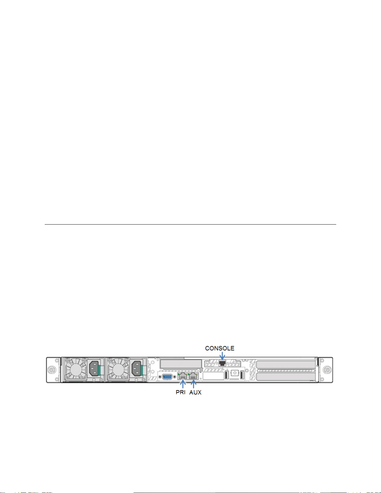
Cabling to the management network
Primary port
Connect a straight-through cable from the management network to the Primary (PRI) connector on back of the Flow
Gateway chassis.
Auxiliary port
If the Auxiliary port is to be used for receiving data or for remote management of chassis-level functions, connect a
straight-through cable from the management network to the to the AUX connector. The Auxiliary port does not need
to be on the same network as the Primary port.
When the remote management feature is used, the network address and login credentials for remote access to the BMC
(baseboard management controller) web user interface are usually configured by a system administrator as part of the
operational configuration after Flow Gateway has been installed. For additional information, complete the installation
and then consult the online help for the Configuration > General Settings page of the web user interface.
Power cabling
If the power cables were not installed when the chassis were mounted inthe racks, install them at this time. If possible,
plug the two power supplies into two different power sources.
The chassis is configured to initialize when power is connected.

SteelCentral™ Flow Gateway Appliance Installation Guide 11
CHAPTER 4 Configuration
The Flow Gateway is shipped from the factory with its software already installed. This chapter describes configuring
the factory-installed software. If instead you want to install and configure new software downloaded from the Riverbed
Support site, refer to Chapter 5, “Installing new software.”
This chapter includes:
“Installation time considerations” on page 11
“Step 1 - Run the configuration wizard” on page 11
“Step 2 - Log in to the web user interface” on page 12
Installation time considerations
The time required for installing the Flow Gateway is shortest if you configure and run the factory-installed software.
If you will be running a version of the software later than the version that was installed at the factory, then there are
two approaches to installing that version:
Configure the factory-installed software as described in this chapter and then update it to the latest version.
Perform a full installation of new software downloaded from the Riverbed Support site. This replaces the factory-
installed software.
If the software version on the Support site is only one or two versions later than the factory-installed version, it may
be faster to configure the factory-installed software and then update it to the latest version. If the software on the
Support site is several versions later than the factory-installed version, it may be faster to download the latest version
from the Support site and perform a full installation. This is described in Chapter 5, “Installing new software.”
To configure and run the factory-installed software, follow the steps below.
Step 1 - Run the configuration wizard
1. On the system that has the cable connected to the Flow Gateway console connector, use your terminal emulator to
log in through the console port. The default login credentials are:
User name: admin
Password: admin

12 SteelCentral™ Flow Gateway Appliance Installation Guide
Configuration Step 2 - Log in to the web user interface
2. When the configuration wizard starts, it displays the product model and serial number. If you will be activating the
licenses manually, record this information to use during license activation.
3. Enter the required information at the prompts. Use your keyboard’s Up Arrow to choose an IPv4 address or an
IPv6 network to pre-populate the Management address field. For IPv6, add the host address before the prefix
length. A typical configuration dialog proceeds as follows:
Welcome to SteelCentral Setup!
Configuring SCFG-02270 with serial number 0000000000000
Press up arrow to access these addresses or ctrl+c to restart
Discovered IPv4 address 10.38.136.55/18
Discovered IPv6 network 2600:809:200:1a02:/64
Please enter the MGMT IP ADDRESS
ip/prefixlen: 2600:809:200:1a02:100:0:a26:8837/64
Please enter the GATEWAY IP ADDRESS
ip: 2600:809:200:1a02::1
Please enter the password for the mazu, dhcp, root, and admin shell users: ********
Please re-enter the password: ********
New Settings:
Product: SCFG-02270
IP Address: 2600:809:200:1a02:100:0:a26:8837/64
Gateway: 2600:809:200:1a02::1
NOTE: Setup will conclude with a reboot of this SteelCentral device. After all modules have
rebooted, setup can be completed by logging into the UI at
https://[2600:809:200:1a02:100:0:a26:8837]/
Login as admin/admin.
NOTICE: All existing settings and logs will be lost.
Finish Setup and Reboot? (yes/no): yes
Working.........
4. When the wizard completes and exits, the system reboots. Wait until the system finishes rebooting before
continuing with the next step.
Step 2 - Log in to the web user interface
1. Using a system that is connected to the management network, point your web browser to the IP address you
specified in the configuration wizard in the previous step.
https://<Flow_Gateway_IP_address>
2. Log in to the Flow Gateway user interface. The default credentials are:
User name: admin
Password: admin
The first time you log in to the Flow Gateway user interface, it displays the Setup page.
3. On the Setup page, ensure that all the required fields (marked with an asterisk) are filled in.

SteelCentral™ Flow Gateway Appliance Installation Guide 13
Step 2 - Log in to the web user interface Configuration
4. At the bottom of the Setup page, click Configure Now.
5. When prompted, enter a new password for the web user interface.
If Flow Gateway has an Internet connection, it will attempt to download licenses from the Riverbed Support site.
Alternatively, you can either add or download applicable licenses using the Flow Gateway Configuration > Licenses
page. Refer to Chapter 6, “Licensing.”

14 SteelCentral™ Flow Gateway Appliance Installation Guide
Configuration Step 2 - Log in to the web user interface

SteelCentral™ Flow Gateway Appliance Installation Guide 15
CHAPTER 5 Installing new software
This chapter describes how to download the software from the Riverbed Support site and install it in Flow Gateway.
It provides a checklist section that can be used as a guide for those familiar with installing software from a USB
memory stick, and more detailed step-by-step instructions explaining items on the checklist.
“Overview” on page 15
“Checklist” on page 16
“Step 1 - Download the software” on page 17
“Step 2 - Create bootable USB memory sticks” on page 17
“Step 3 - Insert the bootable USB memory stick into the system” on page 17
“Step 4 - Connect to the console port” on page 17
“Step 5 - Configure the BIOS” on page 17
“Step 6 - Install the software” on page 18
“Step 7 - Remove the USB memory stick” on page 18
“Step 8 - Run the configuration wizard” on page 18
“Step 9 - Log into the web user interface” on page 19
Overview
Flow Gateway is shipped from the factory with its software already installed. You can configure the factory-installed
software and begin using the product, or you can perform a complete installation of software downloaded from the
Riverbed Support site.
To configure and run the factory-installed software, refer to Chapter 4, “Configuration.” To download a new copy of
the software from the Riverbed Support site, follow the instructions in this chapter.

16 SteelCentral™ Flow Gateway Appliance Installation Guide
Installing new software Checklist
Checklist
Briefly, the installation procedure involves the following tasks:
1. Download the software installation image file from the Riverbed Support site.
2. Create a bootable (live) USB memory stick.
3. Plug the bootable USB memory stick into a USB connector on the front of the chassis.
4. Use a terminal emulator and the cable supplied in the accessory kit to connect to the console port connector on the
back of the chassis.
5. Switch on or power-cycle the Flow Gateway. During the power-on self-test (POST) sequence, configure the BIOS
to boot from an external USB device. The power switch is in the upper right corner of the front of the chassis.
6. When the system boots from your USB stick and displays the boot prompt, enter “install” and wait for the system
to install the software. This requires approximately 20 minutes.
After the installation process completes, the localhost.localdomain login prompt is displayed.
7. When the software installation has completed and the “boot” prompt is displayed, remove the USB memory stick
and power-cycle the appliance. After the system reboots, the login prompt is displayed.
8. Run the configuration wizard. To start the wizard, log in using “admin” for your user name and “admin” for your
password. Enter the required information when prompted by the configuration wizard. The system reboots when
you exit from the configuration wizard. Wait for it to finish rebooting before continuing to the next step.
9. Log into the web user interface from a management system on the network.
10. The first time you log in, the initial Setup page is displayed. Enter the required information in all the fields marked
with an asterisk (*).
11. At the bottom of the Setup page, click Configure Now to complete the configuration.
12. When prompted, enter a new password for the web user interface.
If the Flow Gateway has an Internet connection, it will attempt to download licenses from the Riverbed Support site.
Alternatively, you can either add or download applicable licenses using the Flow Gateway Configuration > Licenses
page. Refer to Chapter 6, “Licensing.”
With no external USB memory stick installed, the product will boot off its internal disks if it loses power or is power-
cycled. However, it may be preferable to reconfigure the BIOS to exclude external USB sticks from the boot order.
The sections that follow describe the installation process in greater detail.
Table of contents
Other Riverbed Gateway manuals

Riverbed
Riverbed SteelConnect SDI-130 User manual

Riverbed
Riverbed SteelConnect SDI-2030 Manual

Riverbed
Riverbed Whitewater User manual

Riverbed
Riverbed SteelConnect SDI-330 User manual

Riverbed
Riverbed SteelConnect SDI-5030 Manual

Riverbed
Riverbed SteelConnect SDI-130W Manual

Riverbed
Riverbed SteelConnect SDI-130 Installation instructions


