manuals.online logo
Brands
  1. Home
  2. •
  3. Brands
  4. •
  5. Dorma
  6. •
  7. Door Opening System
  8. •
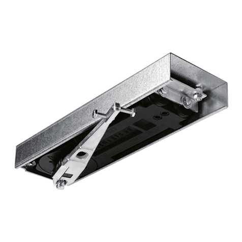
  9. Dorma PORTEO Instruction manual

Dorma PORTEO Instruction manual

I. Installation on the push and pull side
1. Define which electrical connections are required:
a) Plug & Go (plug mains connector into mains outlet)
or
b) Direct mains connection (cable from the wall)
Work must be carried out by a qualified
electrician!
2. Installation
a) Transom fixing (standard)
See installation drawings
b) Door leaf fixing
See installation drawings
Cable loop required!
3. Once installed, commission PORTEO as follows.
II. Standard commissioning procedure
For transom-fixed units with slide channel on the pull side, on
doors up to 60 kg in leaf weight and up to 1000 mm in width.
If these limits are exceeded, perform the advanced
commissioning procedure – see Operating Manual.
1. Connect mains supply.
2. Switch mains disconnector to “OFF”.
3. Set programme switch to “0”.
4. Determining the direction of door opening:
a) Open door approx. 5°.
b) At the same time, press and hold the Service
pushbutton and switch the mains disconnector to
“ON”; maintain these settings until door moves
(approx. 8 sec.).
c) Release Service pushbutton (green LED flashes).
d) Door moves to “Door Closed” position (direction of
door swing has now been stored).
5. Determining the “Door Opened” position:
a)
Move door to required Open position (max. 110°)
(green LED flashes).
b) Press the Service pushbutton once and then
release (green LED glows for 3 sec., then flashes).
Start of the learning (teach-in) cycle (do not
interrupt this).
c) Door moves to “Door Closed” position
(“Door Opened” position has now been stored).
The PORTEO is now ready to operate.
6. Advance settings.
Changing the settings of the potentiometers
(see Item V).III. Programmschalter
III. Programme switch
Switch position 0 = OFF
– The electrical functions of the PORTEO are
switched off.
– The door can be operated using a lever handle or a
key.
Switch position I = Operating modes.
– The electrical functions of the PORTEO are
switched on.
Switch position II = Permanent Open
– PORTEO holds the door open for as long as is
required.
Perma
nent Open function also available as an option in
conjunction with a pushbutton activator: Briefly press
the pushbutton twice (current impulse relay function).
Or programmable with handheld transmitter.
IV. Operating modes
1. “PowerLess” mode
– Effortless manual opening of door with lever handle.
– For doors with standard lock and lever handle.
Setting the “PowerLess” mode:
1. Switch mains disconnector to “ON”.
2. Set programme switch to “I”.
3. Rotate potentiometer 1 (Speed) fully counter-clock-
wise to the “PowerLess” position.
2. “Push&Go” mode
– Manual opening of door – from 3° PORTEO cuts in
to open the door automatically.
– For doors with standard lock and lever handle.
Setting the “Push&Go” mode:
1. Switch mains disconnector to “ON”.
2. Set programme switch to “I”.
3. “Push&Go” automatically cuts in from a door
opening angle of 3°.
Potentiometer 1 (Speed) needs to be turned
anywhere away from the “PowerLess” position.
3. “PowerMotion” mode
Automatic door opening and closing. For doors with a
standard lock,
electric strike
and
external activators
(optional accessories).
Setting the “PowerMotion” mode:
1. Switch mains disconnector to “ON”.
2. Set programme switch to “I”.
Potentiometer 1 (Speed) needs to be turned
anywhere away from the “PowerLess” position.
For more information on the PowerMotion mode and
requisite accessories, see back page!
V. Potentiometer (controller) and DIP switch settings
Potentiometers should be adjusted using the
special tool only.
Adjusting the opening and closing times (Speed)
5 – 10 sec.
1. Switch mains disconnector to “ON”.
2. Using potentiometer 1 adjust the opening and
closing time (Speed)
(infinitely adjustable, factoring setting 10 sec.
operating time).
– = Lowest speed (10 sec. operating time)
+ = Highest speed ( 5 sec. operating time)
Make sure that you do not confuse the positions
“PowerLess” and lowest speed (just before the
“PowerLess” position).
Adjusting the hold-open time
Hold-open time = Time between end of opening operation and start
of closing operation
5 – 30 sec
.1. Switch mains disconnector to “ON”.
2. Using Potentiometer 2, adjust the hold-open time
as required:
– = 5 sec. hold-open time
+ = 30 sec. hold-open time
0,5–30sec.
in the “PowerLess” mode:
– = 0.5 sec. hold-open time
+ = 30 sec. hold-open time
Settings in combination with an electric strike (option)
Once commissioning has been completed, set DIP switch A to
activate the electric strike.
Set DIP switch A to “ON”.
This activates the “electric strike” function.
0,2–3sec.
Adjusting the unlocking time
Unlocking time = Time that elapses between the
activation signal and start of the door opening cycle.
Using Potentiometer 4, adjust the unlocking time
as required:
– = 0.2 sec. unlocking time
+ = 3 sec. unlocking time
During the unlocking time, the door is slightly pul-
led into the frame so that the latch does not jam
or stick. So make sure the unlocking time is not
too short!
Activating/De-activating the latching action:
Latching action = Acceleration of the closing speed over the last
few degrees of the closing sweep to ensure latch engagement.
DIP switch A to “ON”:
Latching action and electric strike activated
DIP switch A to “OFF”:
Latching action and electric strike de-activated
E F G H
AB C D
01 C23/10
VA
Service-
Taster
max. 110°
PowerLess
position
S
p
e
e
d
PowerLess
position
S
p
e
e
d
S
p
e
e
d
PowerLess
position
10 sec
h
o
l
d
-
o
p
e
n
t
i
m
e
u
n
l
o
c
k
i
n
g
t
i
m
e
ON
A
OFF
BCD
123 4
PORTEO. Quick-Start Manual.
PowerLess
position
S
p
e
e
d
ON
A
OFF
BCD
123 4
PORTEO
In the PowerMotion mode (automatic door opening, automatic door closing), an electric strike is needed in order to release
the door latch. A signal is emitted by an external activator, the door opens on release of the latch by the electric strike, and
then automatically closes after a preset hold-open time.
Electric strike with adjustable latch, suitab-
le for over-rebated and flush-closing doors,
non-handed. 24 V DC, 130 mA
Models:
– Basic: Fail-secure (locked when power
disconnected), Art. No. 15117124
– Basic-Safe: Fail-safe (unlocked when
power disconnected), Art. No. 15137124
Accessories: Stainless steel striking plate
type FLM 24, Art. No. 15180224
DORMA RC-R radio receiver DORMA RC-T handheld transmitter
Technical data
Frequency: 433.92 MHz
Output: 1 channel, floating N.O. contact,
self-learning for up to 64 transmitters
Power supply data: 24 V DC
Current input: max. 100 mA
Art. No.: 16562301170
Technical data
Frequency: 433.92 MHz, 4 channels,
digitally coded, with individual
assignability
Power supply: 12 V battery
Range: 15 m indoors
Art. No.: 16562101170
1U
3
42
3
1U
3
42
3
1U
64
63
62
CN
3
StartStart
ON
ON
12
S1W
1
L
1.
Jumper 1U to 64 = Basic electric strike (fail-secure)
Electric strike connections
Activator connections (e.g.
pushbutton unit, radar detector)
Activator connections (e.g.
pushbutton unit, radar detector)
Terminal diagram: Electric strike and activator
The DORMA RC-T enables doors to be opened and closed by radio
remote control. Several transmitters can be married to each receiver.
Each transmitter must be programmed/married individually.
Functional description
Function 1 – Open Door
Press the programmed pushbutton on the transmitter:
• The door moves to the Opened position and closes after the
preset hold-open time.
Function 2 – Permanent Open
Press the programmed pushbutton on the transmitter:
• The door moves to the Opened position and remains there.
Press the same pushbutton again: Door closes.
Programming
Function 1 – Open Door
1. Briefly depress the SW pushbutton on the RC-R receiver PCB.
• The LED on the pushbutton glows for 5 sec.
2. During these 5 sec., press one of the pushbuttons on the trans-
mitter.
• Function 1 is programmed and is available at this pushbutton.
Function 2 – Permanent Open
1. Depress the SW pushbutton on the RC-R receiver PCB until the
LED next to the pushbutton extinguishes again.
• The LED flashes 30 times.
2. This is followed by a brief steady glow (approx. 3 sec.). As soon as
you see this steady glow, press a pushbutton on the transmitter.
Cancelling the programmed settings
The programming must be cancelled before the pushbuttons are
re-assigned with different functions.
1. Switch off the RC-R receiver (switch mains disconnector to “OFF”).
2. Press and hold pushbutton SW on the RC-R receiver PCB.
3. Switch on power again (mains disconnector “ON”).
• LED lights up
4. Release pushbutton SW immediately.
The DORMA RC-R radio receiver (required for the RC-T handheld
transmitter) is installed in the PORTEO unit. When using the RC-T
handheld transmitter, therefore, there is none of the cabling that
otherwise has to be installed for door activation.
Installation of the RC-R radio receiver
1. Remove the backplate from the receiver PCB.
2. Connect the wires from the PORTEO to the PCB
as indicated by the colour code.
3. Once the handheld transmitter has been
programmed/married to the receiver,
wrap the PCB in sponge rubber and slide
into the compartment.
ON
12
-
+
Antenna
V AC/DC
violet
orange
blue
green
yellow
2.
RC-R receiver
ON
12
SW
L1
3.
Set switch 1 to
OFF = 24 V AC/DC.
DORMA System 55 handheld pushbutton
Once the PORTEO has been commissioned, set DIP switch A to on
to activate the electric strike. For other settings, see front page.
Art. No.:
19144701170
Function 1 – Open Door
Press pushbutton:
• Door opens and closes
Function 2 – Permanent Open
1. Quickly double-click pushbutton (current
impulse relay function):
• Door opens and remains in that position.
2. Quickly double-click pushbutton again:
• Door closes.
DORMA Basic electric strike
Jumper 1U to 63 = Basic-Safe electric strike (fail-safe)
PORTEO. Accessories.
WN 057 323 45532, 03/08 Subject to change without notice.

Other manuals for PORTEO

2

Other Dorma Door Opening System manuals

Dorma AS 350 User manual

Dorma

Dorma AS 350 User manual

Dorma TS 68 User manual

Dorma

Dorma TS 68 User manual

Dorma ED 100 Installation and operation manual

Dorma

Dorma ED 100 Installation and operation manual

Dorma CS 80 MAGNEO User manual

Dorma

Dorma CS 80 MAGNEO User manual

Dorma UNIVERSAL ARCOS User manual

Dorma

Dorma UNIVERSAL ARCOS User manual

Dorma PT 40 User manual

Dorma

Dorma PT 40 User manual

Dorma 8916 JT User manual

Dorma

Dorma 8916 JT User manual

Dorma 8916 FT User manual

Dorma

Dorma 8916 FT User manual

Dorma ED400 User guide

Dorma

Dorma ED400 User guide

Dorma 8600 EMR Series User manual

Dorma

Dorma 8600 EMR Series User manual

Dorma ES 200 User manual

Dorma

Dorma ES 200 User manual

Dorma PT 51 User manual

Dorma

Dorma PT 51 User manual

Dorma 7300 Series User manual

Dorma

Dorma 7300 Series User manual

Dorma 7300 DS User manual

Dorma

Dorma 7300 DS User manual

Dorma 8616 FH User manual

Dorma

Dorma 8616 FH User manual

Dorma PORTEO User manual

Dorma

Dorma PORTEO User manual

Dorma MUTO COMFORT L 80 User manual

Dorma

Dorma MUTO COMFORT L 80 User manual

Dorma UNIVERSAL Motion User manual

Dorma

Dorma UNIVERSAL Motion User manual

Dorma 7400 AO8 User manual

Dorma

Dorma 7400 AO8 User manual

Dorma TS93-5 PKT 90/119 User manual

Dorma

Dorma TS93-5 PKT 90/119 User manual

Dorma EM User manual

Dorma

Dorma EM User manual

Dorma RSP 80 User guide

Dorma

Dorma RSP 80 User guide

Dorma 8956 AF89 PD User manual

Dorma

Dorma 8956 AF89 PD User manual

Dorma ES 200 T Easy Manual

Dorma

Dorma ES 200 T Easy Manual

Popular Door Opening System manuals by other brands

Scrigno antamatic OPEN 2.0 installation manual

Scrigno

Scrigno antamatic OPEN 2.0 installation manual

GEZE TSA 160 NT Mounting and service instructions

GEZE

GEZE TSA 160 NT Mounting and service instructions

Overhead door RHX NEMA 7 installation manual

Overhead door

Overhead door RHX NEMA 7 installation manual

Assa Abloy G-CO-CS Mounting instructions

Assa Abloy

Assa Abloy G-CO-CS Mounting instructions

Kaba SLA operating instructions

Kaba

Kaba SLA operating instructions

GEZE EC drive H KIT VP Pre-installation instructions

GEZE

GEZE EC drive H KIT VP Pre-installation instructions

Next Systems 900 INSTRUCTIONS MANUAL FOR THE USE & MAINTENANCE

Next Systems

Next Systems 900 INSTRUCTIONS MANUAL FOR THE USE & MAINTENANCE

Siemens RHFF manual

Siemens

Siemens RHFF manual

tau T-SIDETD installation guide

tau

tau T-SIDETD installation guide

Record K 32 M user manual

Record

Record K 32 M user manual

PDQ 5100 Instruction

PDQ

PDQ 5100 Instruction

schmersal AZ 01 operating instructions

schmersal

schmersal AZ 01 operating instructions

B&D Roll-A-Door R1N installation instructions

B&D

B&D Roll-A-Door R1N installation instructions

GEZE TS 4000 R installation instructions

GEZE

GEZE TS 4000 R installation instructions

BFT BOTTICELLI SMART BT A 850-1250 Installation and user manual

BFT

BFT BOTTICELLI SMART BT A 850-1250 Installation and user manual

Yale PR3301 installation instructions

Yale

Yale PR3301 installation instructions

Johnson Controls MC-302E PG+ installation guide

Johnson Controls

Johnson Controls MC-302E PG+ installation guide

Auta 700105 manual

Auta

Auta 700105 manual

manuals.online logo
manuals.online logoBrands
  • About & Mission
  • Contact us
  • Privacy Policy
  • Terms and Conditions

Copyright 2025 Manuals.Online. All Rights Reserved.