ELTRA CS-2000 User manual

© Eltra GmbH, 42781 Haan, Retsch-Allee 1-5, Germany | 08.08.2016 Version 0001
Service Manual
CS-2000 Carbon / Sulfur Determinator
Translation

2
Copyright
© Copyright by
Eltra GmbH
Retsch-Allee 1-5
D-42781 Haan
Germany

3
Table of Contents
1Notes on service instructions 7
1.1 Explanations of the Safety Instructions 7
2Discharging the oscillator 8
3Faults 12
3.1 Check base lines 12
3.2 Fluctuating gas flow 13
3.3 No combustion 18
3.3.1 Induction furnace operation 18
3.3.2 Resistance furnace operation 27
3.4 Bad combustion 27
3.4.1 Induction furnace operation 27
3.4.2 Resistance furnace operation 28
3.5 Furnace does not close 30
3.6 Analysis takes too long 32
3.6.1 RF-interference on the IR-cell, or on the electronic units 33
3.6.2 Additional reasons for excessive analysis duration 34
3.6.3 One of the IR-sources is unstable 34
3.6.4 The power voltage sinks below 180 VAC 34
3.7 Development of dust when closing the furnace 35
3.8 Erratic results 35
3.9 The results are always 0.0000% or 00.0ppm: 37
3.10 No oxygen flow 38
3.10.1 Induction furnace operation 38
3.10.2 Other faults 39
3.10.3 Resistance furnace operation 39
3.11 IR-cell temperature control is out of range 39
3.12 Breaker turns off at the beginning of combustion 39
3.13 Breaker turns off at the end of the analysis 43
3.14 Dustcloud when opening the furnace 44
3.15 No or low oxygen pressure 45
3.16 Waiting for stability message 47
3.17 Combustion tube breaks frequently 48
3.18 Oxygen pressure falls when the furnace opens 49
3.19 Combustion without starting analysis 50
3.20 Crucible or boat cracks or melts 52
3.20.1 Induction furnace 52
3.20.2 Resitance furnace 52
3.21 Oxygen pressure goes up very slowly 52
3.22 Pump voltage too high 54
3.23 Resistance furnace takes too long to warm up 58
3.24 Negative drift after start 59
3.25 Resistance furnace completly cold or too hot 60
3.26 Fumes in the resistance furnace 61
3.27 Resistance furnace doesn`t reach full temperature 62
3.28 Unstable resistance furnace temperatur 62
3.29 Dust or soot from the resistance furnace 63

4
3.30 Vibrations in induction furnace mode 64
3.31 Analysis cycle stops too early 64
3.32 Chopper motor doesn‘t rotate 65
3.33 Sample burns but no peak on the screen 65
3.34 IR signal does not come down to the base line at the end of analysis 66
4Adjustments 70
4.1 Gas flow controller-adjustment and jumper settings 70
4.1.1 Flow controller for induction furnace operation 70
4.1.2 Flow controller for resistance furnace operation 73
4.2 Infrared base line adjustments 75
4.2.1 Infrared cell modification - general information 75
4.2.2 General test points 78
4.2.3 Test points IR-ranges 79
4.2.4 Base line adjustments. 80
4.2.5 Infrared cell board IRC1.x sections assignment 80
4.2.6 Voltage of a base line is too high (higher than 9.5V) 81
4.3 IR source voltage setting 83
4.4 Infrared cell temperature regulation 84
4.5 Pneumatics 86
4.6 Pressure regulation 90
4.7 Closing cone adjustment 92
4.8 Linearity correction 93
4.9 Induction generator control 94
4.10 Resistance furnace 96
4.10.1 Setting the furnace regulation card TH 43 / TH 44 96
4.10.2 Furnace regulation board TH 43 / TH 44 97
4.11 Thermocouple testing 98
5Service 99
5.1 IR-paths, cleaning and replacing 99
5.2 Infrared electronics 100
5.2.1 Removing the IRC-board 100
5.2.2 Changing the IR-source 101
5.3 Chopper 102
5.4 Leak checking 104
5.5 Solenoid valves cleaning 108
5.6 Flow sensor replacement 110
5.7 Gas pump replacement 111
5.8 Thermocouple replacement 112
5.9 Gas saving mode 114
5.10 Gas saving also for resistance furnace 115
5.11 Furnace pneumatics - additional safety features (optional) 116
5.12 Halogen trap - installing 117
6Miscellaneous 118
6.1 Ordering numbers 118
6.1.1 Front side 118
6.1.2 Left hand side 120
6.1.3 Right hand side 122

5
6.1.4 Induction furnace 124
6.1.5 Furnace cleaning 126
6.1.6 Oscillating circuit 127
6.1.7 Infrared cell 129
6.1.8 Chopper 131
6.1.9 Resistance furnace 132
6.1.10 Oxygen purifying furnace 134
6.1.11 Dust trap 135
6.2 Wiring diagrams 137
6.2.1 Right hand side power wiring 137
6.2.2 Left hand side power wiring 138
6.2.3 Valve wiring 139
6.2.4 Control signal wiring 140
6.2.5 IR-current supply, old version 141
6.2.6 IR-cell internal signals 142
6.2.7 Amplitude circle 143
6.3 Gas flow diagrams 144
6.3.1 Gas flow for induction furnace when furnace is closed 144
6.3.2 Gas flow for induction furnace when furnace is open 145
6.3.3 Gas flow for resistance furnace 146
6.3.4 Valve contolling 147
6.4 Spare parts kits 148
6.4.1 Common spare parts kti for all analysers 148
6.4.2 Spare Parts kit for CS2000 (including spare parts kits CS800 and HTF540) 150
6.5 Maintenance 152
7Approved methodologies to which Eltra instruments conform 153
7.1 Inorganic materials (Metals) 153
7.2 Organic materials (Oil, Coal, foodstuffs) 154
8Disposal 155
9Index 156

Notes on service instructions
6

Notes on service instructions
7
Pos: 1.1/ 0025Ü berschriften/ 1.Übers chriften/1 Hinweise zur Servic eAnl eitung @ 7\mod_1379492 578032_9.docx @ 48845 @ 1 @ 1
1 Notes on service instructions
Pos: 1.2 /0025 Überschrift en/1.1 Überschrift en11 Erklärungen zu d enSic herheitshinw eisen @ 0\mod_1222 344569771_9.doc x@ 2484 @ 2 @ 1
1.1 Explanations of the Safety Instructions
Pos: 1.3 /0010 ELTRA/ 0099 Geräteneutral/St andard Module Eltra /9907Standard Mo dulW arnhinweise Er klärung_aktuell_Eltra @ 8\ mod_1397 552832630_9.doc x @60 674 @ @ 1
In this Operating Manual we give you the following safety warnings
Mortal injury may result from failing to heed these safety warnings. We give you the following
warnings and corresponding content.
DANGER
Type of danger / personal injury
Source of danger
–Possible consequences if the dangers are not observed.
•Instructions on how the dangers are to be avoided.
We also use the following signal word box in the text or in the instructions on action to be taken:
DANGER
Serious injury may result from failing to heed these safety warnings. We give you the following
warnings and corresponding content.
WARNING
Type of danger / personal injury
Source of danger
–Possible consequences if the dangers are not observed.
•Instructions on how the dangers are to be avoided.
We also use the following signal word box in the text or in the instructions on action to be taken:
WARNING
Moderate or mild injury may result from failing to heed these safety warnings. We give you
the following warnings and corresponding content.
CAUTION
Type of danger / personal injury
Source of danger
–Possible consequences if the dangers are not observed.
•Instructions on how the dangers are to be avoided.
We also use the following signal word box in the text or in the instructions on action to be taken:
CAUTION
In the event of possible property damage we inform you with the word “Instructions” and the
corresponding content.

Discharging the oscillator
8
NOTICE
Nature of the property damage
Source of property damage
–Possible consequences if the instructions are not observed.
•Instructions on how the dangers are to be avoided.
We also use the following signal word in the text or in the instructions on action to be taken:
NOTICE
2 Discharging the oscillator
Pos: 3/ 0015 ELTRA/0 099 Geräteneutral/St andard Module Eltra/9 918 Standard Mod ulEntl aden des Oscillat orsCS 800/2000 @ 11\ mod_1440744686 940_9.docx @ 87278 @ @ 1
In order to carry out work on the oscillator of the CS800/2000, it is necessary to ensure that the
oscillator has no stored energy. This is achieved by short circuiting the various potentials.
Attention:
This activity may only be carried out by a qualified electrician with sound knowledge of the
CS800/2000 devices.
Only the Eltra discharge set (Order Number 11001-2005) may be used for discharging. The
discharge set must always be inspected for visible faults before use.
1000V insulating gloves (order number 8840-0453) must be worn during the discharging
process to prevent an electric shock.
The protective measure is only effective if the discharge set and the insulating gloves are
always worn together.
Discharge set: 11001-2005
Insulating gloves 1000V: 88400-0453

Discharging the oscillator
9
Implementation:
Disconnect the mains plug.
Use a multimeter to check that the device is
voltage-free
Remove the housing cover on the device and
disconnect the GND connector

Discharging the oscillator
10
The clamp is attached to the mounting bracket of
the oscillator
In order to guarantee a safe GND connection
between the crocodile clip and the device ground,
a multimeter is used to ensures that the transition
resistance of the set to the device ground is low
(R<1 Ohm).
To do this, one of the measuring tip on the
multimeter is held on the protective earth of the
device. The other measuring tip is connected to
the tip of the discharge set.
Attention!
The oscillator cover must be removed carefully to
expose the transformer connectors

Discharging the oscillator
11
Attention!
The measuring tip is now held first on the left-hand
and then on the right-hand 4.4 KV connector of the
transformer for approx. 5s
It is necessary to ensure that the tip stays on each
contact for the full 5s.
Attention!
All marked components inside the oscillator are short circuited to ground using the measuring tip.
Pos: 4/ 0015 ELTRA/------- Seitenumbruc h----------- @ 6\mod_13 68796429449_0.doc x@ 414 68@ @ 1
Pos: 2/ 0010 ELTRA/------- Seitenumbruc h----------- @ 6\mod_13 68796429449_0.doc x@ 414 68@ @ 1

Faults
12
Pos: 3.1/ 0025Ü berschriften/ELTR A 1.Ü berschriften/1 Faults Eltra @ 8\mo d_1396880810332_ 9.docx@ 6 0058 @ 1@ 1
3 Faults
Pos: 3.2/ 0025 Überschriften/ELTR A 1.1Ü berschriften/11 Chec kb aselin esEL TRA @ 6\mod_13684522 66990_9.docx @ 40029 @ 2 @ 1
3.1 Check base lines
Pos: 3.3/ 0010 ELTRA/0015 ser vice_instructions/CS- 2000_service/05Faul ts_CS-2000/0505 Mo dulCh eckb asel ines @ 9\mod_14255390 18921_9.docx @ 74093 @ @ 1
When this message appears on the PC screen, at least one of the base lines is either over
+9.5Volts or below -9.5 Volts.
In order to read the base line voltages of all IR cells available, click on “base lines”
Fig.
1
: Base line button
A window appears at the right upper end of the screen showing the base lines moving from the
left to the right (time coordinate). In the middle of the right end of this base lines window, there
is a small button. After clicking on it, a new window appears, displaying the base line voltages,
described as “Inputs” and their “Averages”.
The description “Inputs” is made from the software point of view. The outputs of the cells are
inputs for the microcontroller board and for the software.
It is advisable to watch the figures under “Inputs”. Do not observe the “Averages” because the
response is delayed when the base lines change. This is a disadvantage when adjusting the
base lines.
Fig.
2
: : Activating Inputs and Averages Window
Fig.
3
: Inputs and Averages Window
If any of the “Inputs” or “Averages” is over 9.5V, adjust a voltage of about 6 to 7V.
See chapter 3.2 “Infrared base line adjustment”.
The adjustment is preferably made when having carrier gas flow through the cells.

Faults
13
Notice
The IR cells have normally base lines adjusted to about 8V and the peak comes down during
analysis, respectively during IR absorption by the measuring gas.
In case of golden paths, in the first couple of months after being in operation, the base line may
goes up, which means that the paths become more reflective during this period. Therefore, the
base lines of golden paths should be initially set rather at 5 or 6 volts instead of 8 volts. In the
first couple of months the base lines go up, but the growing slows down and growing
contamination finally causes the base line to start coming down.
The initial base line adjustment at 5 to 6 volts, prevents the maximum base line value from
reaching 9.5V, where the error message “Check base line” appears. Note that this message is
just a warning. The analyzer is not prevented from carrying out further analyses. As long as the
base line remains below 10V, the results are correct.
If a base line is below -9.5V, an adjustment should be done as advised above. If this is not
possible, then most probably there is a fault or a very strong contamination. See chapter 4.1 “IR
paths cleaning”. In case of contamination, all cells available should have very low voltages,
even negative ones.
If all available cells are below -9.5V there is most probably a fault that is common for all cells
like no rotating chopper motor or a faulty infrared source. See chapter 2.35 “The chopper
motor doesn’t rotate” and 3.3 “IR source voltage setting”.
See also Chapter 3.4 “Analysis takes too long / RF-interference on the IR-cell, or on the
electronic units”
Pos: 3.4/ 0025Ü berschriften/ELTR A 1.1Ü berschriften/11 Fluctu ating gas flow ELTRA @ 6\mod_136845 2950593_9.docx @ 40051 @ 2 @ 1
3.2 Fluctuating gas flow
Pos: 3.5 /0010 ELTRA/ 0015s ervice_instr uctions/CS-2000_s ervice/05Faults_C S-2000/0510 Mo dulF luctuating gas flow @ 9\ mod_14255391 77355_9.docx @ 7410 5 @ @ 1
Fig.
4
: Fluctuating gas flow
The flow rate is electronically controlled; therefore there should be no significant variation from
the set value.
6
7
5

Faults
14
In case of a fault however, a control of the flow rate is no longer possible and the gas flow
fluctuates. This can be caused, for example, by an excessive obstruction of the gas flow system
or by a faulty component that needs to be replaced.
See the next pages of this chapter and chapter 3.1 “Gas flow controller adjustment and
jumper settings”
Mostly, the problem lies in the saturation of the dust trap or of the chemicals.
In case the flow becomes lower and the regulating valve or the pump voltage goes higher
during combustion, it is obvious that the flow regulator is working. Therefore the problem must
be a restricted oxygen supply. When the accelerators start burning they take a lot of oxygen, so
that the pressure in the furnace goes down, and as a result for this the flow may also go down
List of fault reasons in order of probability: (Details to the above points)
Induction furnace
Resistance furnace
1. Blocked metal dust filter
1. Blocked chemicals
2. Blocked chemicals
2. Blocked furnace outlet
3. Blocked paper filters
3. Too low oxygen pressure
4. Blocked lance hole over the crucible.
4. The outlet tap of the oxygen bottle is
not properly open
5. Blocked hole of the ceramic heat
shield
5. A heavy item is placed on the plastic
tube of the oxygen supply
6. Too low oxygen pressure
6. Twisted plastic tube inside the
analyzer
7. The outlet tap of the oxygen bottle is
not properly open
7. Blocked dust filter cartridge
8. Faulty oxygen regulator
8. Blocked fittings
9. Contaminated or corroded solenoid
valve
9. Blocked flow sensor assembly
10. Bent plastic tube of oxygen supply
10. Electronic problem
11. A heavy item is placed on the plastic
tube of the oxygen supply
11. Weak gas pump
12. Twisted plastic tube inside the
analyzer
13. The oxygen supply is interchanged
with the compressed air supply
14. Blocked dust filter cartridge
15. Blocked flow sensor assembly
16. Electronic problem
Blocked metal dust filter:
Clean the metal dust filter according to the operation manual.
Caution: Even if the filter may be brushed and cleaned in ultrasonic cleaner, some day will not
be able to be cleaned any more. The filter doesn't last forever.

Faults
15
Check by removing the filter with the dust filter housing. See chapter: “High carbon results are
erratic”.
Don’t remove the filter from its housing.
Turn the filter housing upside down and try to blow air through the smaller whole (about 16mm
diameter) of the filter housing.
If you feel a remarkable restriction, replace the filter by a new one. With a new filter the air
should pass practically free without any restriction.
Blocked chemicals:
The grains of magnesium perchlorate as well as of sodium hydroxide have to move when
knocking on their glass tube. If they are cloggy, they are completely depleted and they have to
be replaced. When the glass tube is turned upside down, the grains should fall off. If a screw
driver is needed to stab the grains free, the chemicals had to be replaced much earlier.
Blocked paper filters:
The paper filters are small so that they are frequently forgotten or neglected, although they can
block the flow when they are not replaced for long.
Blocked lance hole over the crucible:
The hole in the ceramic heat shield over the crucible in the induction furnace can be restricted
or blocked.
Clean by using the brass brush as described in the operation manual. If this may not be enough
then clean the hole by using a piece of wire or a pipe cleaner.
Blocked furnace outlet:
For induction furnace, unscrew the cap-nut at the furnace outlet and remove the plastic tube.
Pass through the fitting a pipe cleaner. Open the furnace in order to be sure that the pipe
cleaner has passed thru the fitting reaching the furnace area.
Completely remove the plastic tube by unscrewing the left hand cap-nut on the dust filter
assembly. Clean this fitting the same way like before. If necessary clean the plastic tube as well.
In case of resistance furnace operation clean the furnace outlet as shown below.

Faults
16
Push the tube (1) through the upper glass tube assembly (2), pass it through the tube (3) up to
the inside of the dust trap box (4).
This should be done when the glass tube has to be removed anyway, for replacing the
magnesium perchlorate (anhydrone). See also operation manual, chapter “Dust cleaning”.
Too low oxygen pressure:
Check the oxygen gauge (6). The reading should be 1.5 bar (22.5psi). If the pressure is too low,
it can be adjusted by pulling and turning clockwise the knob of the pressure regulator on the
rear panel of the analyzer. It is placed on the left hand side and the knob is accessible from
inside the analyzer. An adjustment is possible provided that there is sufficient pressure at the
input of this pressure regulator.
Outlet tap of the oxygen bottle is not properly open:
It is important to properly open the small tap at the outlet of the pressure regulator of the oxygen
bottle. If this outlet tap of the regulator is not properly open, you may have enough pressure at
the analyzer when there is no or little oxygen demand. But when the oxygen demand grows, for
example at the beginning of combustion in the
induction furnace when the sample needs a lot of oxygen to burn, the pressure may drop to a
very low level if not enough oxygen can be supplied to the analyzer at the moment of high
oxygen demand. The same problem will appear during furnace purging before or after the
analysis, depending on the actual settings in the software.
Contaminated or corroded solenoid valve:
In case of exceptional materials like ores, solenoid valves can be contaminated up to the extent
of failing. This depends mainly on the amount of sulfur and moisture in the sample. The most
affected valves are the outflow valve V1 and the bypass valve V4 in as well as the valves
switching from Induction to resistance furnace V11 and V12. See chapter “Gas flow system”.
The resistance furnace operation can only contaminate V11 and V12. The valves can be
cleaned.
Faulty oxygen regulator:
A faulty oxygen regulator can of course cause a similar problem when it does not keep the
pressure level at moments of higher oxygen consumption.
Bent plastic tube of oxygen supply:
When the plastic tube supplying oxygen from the bottle to the analyzer is bent, there will be the
same problem like described in the above two subjects. There will be too low oxygen pressure
in the analyzer, especially at moments of high oxygen consumption, like when burning samples
or purging the furnace.
Oxygen supply is interchanged with the compressed air supply:
In case of reported bad combustion, check for correct connection of oxygen and compressed air
supply. Compressed air in the induction furnace will provide combustion but a bad one, because
of only 20% of oxygen existing in the air. Therefore the peaks are low and long, consisting of
more than one peak, looking like mountains.
CAUTION Oxygen to the compressed air inlet can lead to the explosion of the pneumatic
cylinder.
Blocked dust filter cartridge:
The dust filter cartridge is on the front panel so that contamination is visible for the operator. In
the gas flow circuit, this dust cartridge is connected after the metal filter and its following glass
tube with magnesium perchlorate, so that the carrier gas passing through the cartridge is
already filtered.

Faults
17
Blocked fittings:
This case is very unlikely to happen in case of induction furnace operation, because the
analyzed materials in question are inorganic materials like metals and ceramics, so that they
don’t create fumes, volatiles and moisture. Even cement analysis is not as critical as organics
analysis. In case of analysis of materials causing major contamination, mainly when analyzing
organic materials in the resistance furnace, the fittings of the IR cells can be blocked so that
they have to be cleaned. See chapter “IR paths cleaning and replacing”.
Also fittings elsewhere can be blocked, like the fittings for plastic tubes on the reagent glass-
tube holders.
Blocked flow sensor assembly:
If the flow sensor is blocked, it should normally be replaced.
For those who may decide to clean them - please read the description about cleaning. Chapter
“Flow sensor replacing / cleaning”.
Electronic reasons for flow problems:
The flow controller consists of 3 components.
Induction furnace operation
1. The flow sensor
2. The board HF-42 (The lower half of the board only).
3. The proportional valve V6 (see chapter “Gas flow system”).
4. Interferences from the induction generator. See chapter “Analysis takes too long / RF-
interference on the IR-cell, or on the electronic units”.
The electronic devices involved in the flow regulation are the board HF-42 and the flow sensor.
The only influence of the PC and of the microcontroller on the flow, is the start/stop the flow, for
example to start it when oxygen pressure available, to stop it in case of gas saving mode etc.
For chasing flow problems, there is a possibility to avoid any involvement of the PC and of the
microcontroller, by setting a jumper on the HF-42. To do this, move the jumper of J3 from A1-A2
to B3-B4. See chapter “Gas flow controller and jumper settings”.
DANGER
G0002
Mortal danger from electric shock
Exposed power contacts - High Voltage
-An electric shock can cause injuries in the form of burns and
cardiac arrhythmia, respiratory arrest or cardiac arrest.
• Disconnect the mains power plug before opening the
analyzer’s cabinet.

Faults
18
Fig.
5
: HF-42
Fig.
6
: Jumper position for gas saving mode
Fig.
7
: Jumper position for continuous flow
In this case there is continuous flow when the main power switch is on Position 2.
Resistance furnace operation:
1. The flow sensor (same sensor also used in induction operation)
2. The electronic board PC-2 (see chapter “Gas flow controller and jumper settings”).
3. The gas pump (see chapter “Gas flow system”).
Pos: 3.6/ 0025Ü berschrifte n/ELTRA 1.1Ü berschriften/11 No combu stion @ 9\mod_14255447 97746_9.docx @ 74944 @ 2 @ 1
3.3 No combustion
Pos: 3.7/ 0010 ELTRA/0015 ser vice_instructions/CS- 2000_service/05Faul ts_CS-2000/0515 Mo dulNo com bustion @ 9\mod_14255393 52573_9.docx @ 74117 @ 33333 334444444 @ 1
3.3.1 Induction furnace operation
After clicking START of analysis or pressing F5 but the sample doesn’t burn, check the reports
in the “status window” on the pc screen.
The following describes how to proceed depending on the displayed message
No oxygen pressure
See Chapter “No or low oxygen pressure”

Faults
19
No flow
If this message permanently remains in the “status window”, check the flow on the lower flow
meter (Rotameter). The ball has to be in the range of 180 L/h. If it is in this range, then click on
the “device state” window icon.
Fig.
8
: device state window icon
Check the graph for L/h. (See software helps). If the vertical bar is not in the middle of the base
line then calibrate the flow in the software as follows.
Pre-purging
If this message permanently remains in the “status window”, click the icon of the “configuration
window”.
Fig.
9
: configuration window icon
The duration of pre-purging is possibly entered much too long. Reasonable values are between
1 and 5 seconds, maximum 10 sec for very low carbon analysis.
Waiting for stability
If this message permanently remains in the “status window”, the infrared cell base lines are not
stable or out of range. Click the Base line Icon and check.
Fig.
10
: Base line icon
Integration delay
The message “Integration delay” appears for as many seconds as entered in the “configuration
window”. Reasonable range is something between zero and 5 seconds. When the integration
delay starts, the induction generator starts at the same time. In other words, the software starts
the integration delay and the generator at the same time. This is valid also when the integration
delay is set to zero seconds. In this case, the generator is started but “Integration delay does
not appear in the status window. The status window displays then the next message of its
sequence, which is “Analyzing”.
Analyzing
When “Analyzing” appears in the status window, it means that definitely the command for
starting combustion is given by the software, so that if still there is no combustion, there must be
probably a hardware reason for this fault.
After starting analysis, the word “Analyzing” appears in the configuration window.
The command from the microcontroller to start the generator is not received

Faults
20
Fig.
11
: Measurements on TP9
1. Measurements on TP9
–a signal of about 0.5 V should turn the generator on,
–a signal of about 12 V should turn the generator off.
If 12 V are measured, despite "Analyzing" appearing on the display, then the microcontroller
board is defective or the connection from the HF 42 circuit board, pin 7 is loose.
Fig.
12
: TP13 test point
When the command for the generator is received ( 0.5 V DC ), the triac triggering pulses must
appear on the TP13 test point. If there is no oscilloscope available you can test this with a digital
voltmeter. The displayed value depends on what type of digital voltmeter you have. There must
be a voltage increase on TP13, once the word "Analyzing" has appeared on the display, or once
0.5 V are present on TP9. When no voltage increase occurs on TP13 , despite having 0.5 V on
TP9; the HF 42 circuit board is defective.
NOTICE
After replacing the HF 42 board, make sure that the 50 pin plug is properly inserted. It takes a
lot of force to push in 50 pins at once. 50 pin plugs that haven’t been properly inserted are a
Other manuals for CS-2000
1
Table of contents
Other ELTRA Measuring Instrument manuals
ELTRA
ELTRA ON-900 User manual
ELTRA
ELTRA CS-i User manual
ELTRA
ELTRA CS-580A User manual
ELTRA
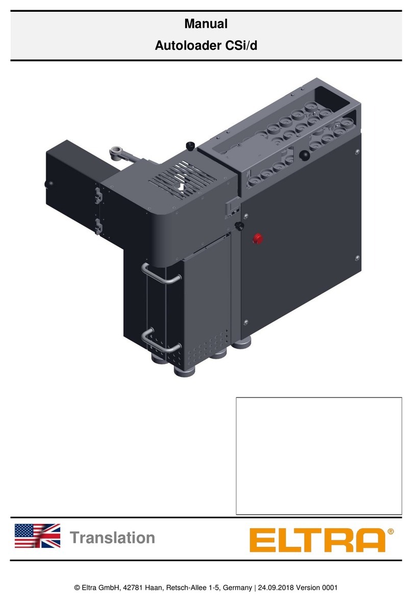
ELTRA CSi/d User manual

ELTRA
ELTRA ELEMENTRAC ONHp2 User manual

ELTRA
ELTRA CS-800 User manual
ELTRA
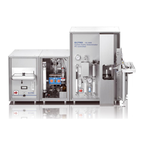
ELTRA CS-2000 User manual
ELTRA
ELTRA CS-800 User manual
ELTRA
ELTRA Thermostep TGA User manual
ELTRA
ELTRA ELEMENTRAC CS-i User manual
Popular Measuring Instrument manuals by other brands

Autometers Systems
Autometers Systems IC 995 Installation and operating manual

Sokkia
Sokkia 130R Series Operator's manual
MGP Instruments
MGP Instruments DRM-1 OPERATION & CALIBRATION MANUAL
Sensus
Sensus Dynamic Series quick start guide

Atal
Atal ATD-06 instruction manual
Siemens
Siemens SITRANS MAG 5100W instructions


