Roban B-25J Mitchell User manual

B-25J Mitchell
RC Airplane KIT
Exclusively for www.scaleflying.com
Manual
FIXED WING RC AIRCRAFT

Copyright@2015 - Roban Limited – All rights reserved
Super Scale RC Airplane Manual – B-25J
Release 1.0 - Jan 2015
Roban Limited
Zhengyacun Industrial Zone, Venture Cross Rd.
Jiaolian, Wanjiang City District of Dongguan,
523046 Dongguan County (GD) - PRC

Copyright@2015 - Roban Limited – All rights reserved
SPECIFICATIONS
Body length: 1566mm
Wingspan: 2060mm
Height: 422mm
Dry weight: 4.5kg
Flying weight: 6.1-7kg
Motor:* 2x 500KV 4020 brushless outrunner, 4-6S capable
Speed controller:* 2x 60A brushless, 4-6S capable
Servo:* 7x metal gear 40g, 2x metal gear wing mount type
Battery:* 2x 18.5V 4000mAh 35C+
Flight time: 8 minutes
Takeoff weight: 8500g
Radio Control:* min. 6 channel with flap program
*) Optionally available equipment
Our goal was to create a high scale detail, high performance airplane, with a minimum of assembly work and simple
maintenance.
Please read this user manual carefully, it contains instructions for the correct assembly of the model.
Please refer to the web site www.robanmodel.com for updates and other important information.
Thank you for your purchase, and have a great time with your Airplane!
Roban Limited

Copyright@2015 - Roban Limited – All rights reserved
IMPORTANT NOTES
*This radio controlled airplane is not a toy.
*This radio controlled airplane can be very dangerous.
*This radio controlled airplane is a technically complex device which has to be built and handled very carefully.
*This radio controlled airplane must be built following these instructions. This manual provides the necessary information
to correctly assemble the model. It is necessary to carefully follow all the instructions.
*Inexperienced pilots must be monitored by expert pilots.
*All operators must wear safety glasses and take appropriate safety precautions.
*A radio controlled airplane must only be used in open spaces without obstacles, and far enough from people to
minimize
the possibility of accidents or of injury to property or persons.
*A radio controlled airplane can behave in an unexpected manner, causing loss of control of the model, and make it a
very
dangerous flying object.
*Lack of care with assembly or maintenance can result in an unreliable and dangerous model.
*Neither Roban Limited nor its agents have any control over the assembly, maintenance and use of this product.
Therefore, no
responsibility can be traced back to the manufacturer. You hereby agree to release Roban Limited from any
responsibility or
liability arising from the use of this product.
SAFETY GUIDELINES
*Fly only in areas dedicated to the use of model airplanes.
*Follow all control procedures for the radio frequency system.
*It is necessary that you know your radio system well. Check all functions of the transmitter before every flight.
*The blades of the model rotate at a very high speed; be aware of the danger they pose and the damage they may
cause.
*Never fly in the vicinity of other people.
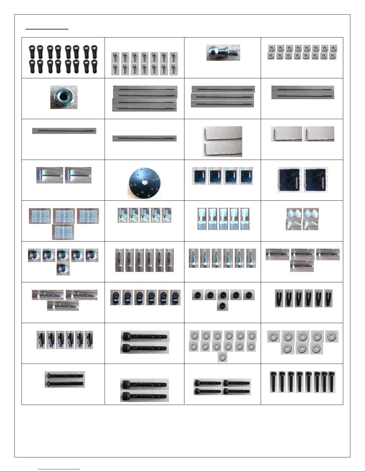
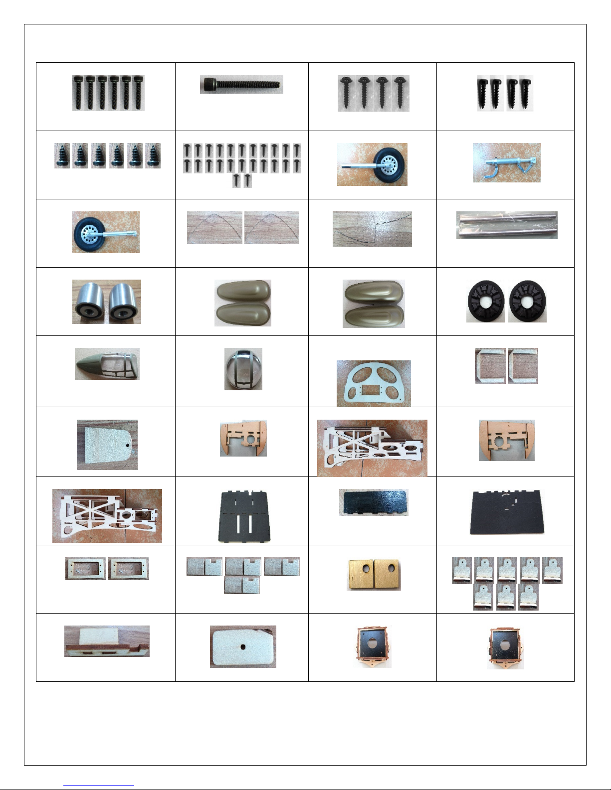
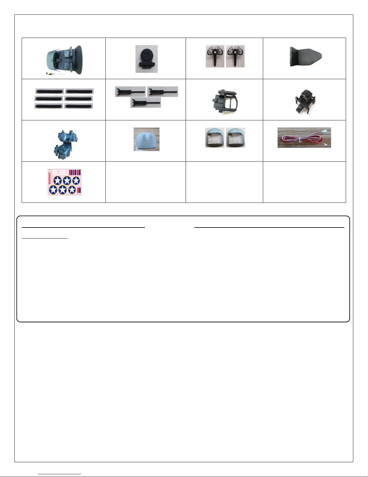
NOTES FOR ASSEMBLY
Please refer to this manual for assembly instructions for this model.
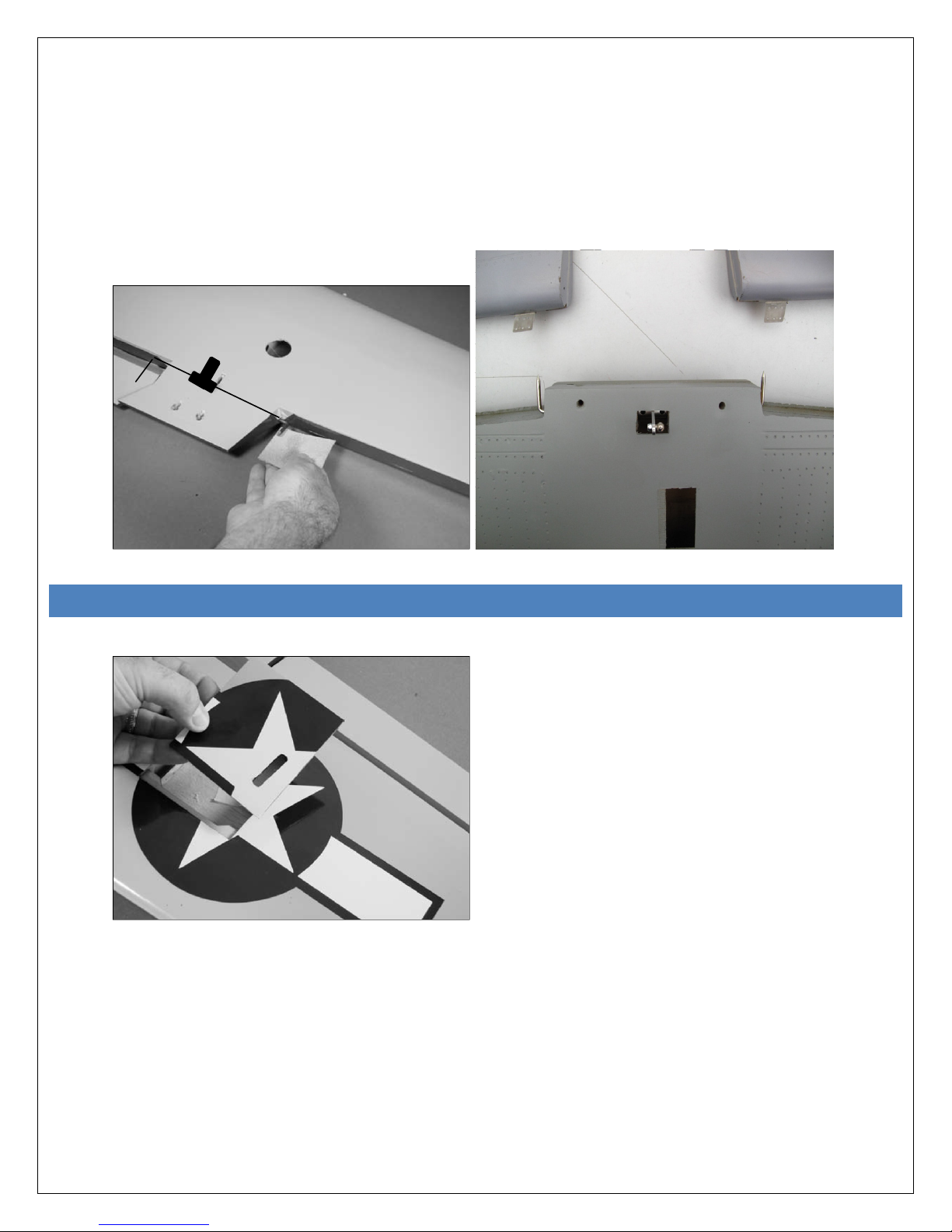
Follow the order of assembly indicated. The instructions are divided into chapters, which are structured in a way that
each step is based on the work done in the previous step. Changing the order of assembly may result in additional or
unnecessary steps.
Use thread lockers and retaining compounds as indicated. In general, each bolt or screw that engages with a metal part
requires thread lock.
Factory pre-assembled components have been assembled with all the required thread lock and lubricants,
and have passed quality control. It is not necessary to disassemble and re-assemble them.
We do not recommend the use of thin cyanoacrylate glue for surface mount of painted parts. The fumes of the curing
glue leave white stains on the clear coat, which are hard to remove.

Copyright@2015 - Roban Limited – All rights reserved
1 – Ball links x16
2 – 5mm Uniball x16
3 – Long Uniball x1
4 – Nut M2 x20
5 – Nut M2.5 x1
6 – Pushrod 2.3x62 x4
7 – Pushrod 2.3x49 x3
8 – Pushrod 2.3x32 x2
9 – Pushrod 2.3x76 x1
10 – Pushrod 2.3x55 x1
11 – L Lever 80/25 x2
12 – L Lever 60/25 x2
13 – T-Junction x2
14 – Servo Disc x1
15 – Servo holder plate x4
16 – Servo holder plate x2
17 – Pin Hinges x4
18 – Hinges x5
19 – Hinges x5
20 – Control horns x4
21 – Control horn washer x6
22 – Screw M2x7 x6
23 – Control horn x6
24 – Screw M3x25 x4
25 – Screw M3x18 x3
26 – Control horn part x6
27 – Control horn part x6
28 – Control clevis x6
29 – Pushrod keepers x6
30 – Screw M3x22 x2
31 – Washer M3x8 x13
32 – Washer M3x10 x8
33 – Screw M4x45 x2
34 – Screw M3x22 x2
35 – Screw M3x18 x4
36 – Screw M3x14 x8
CONTENTS:

Copyright@2015 - Roban Limited – All rights reserved
37 – Screw M3x12 x6
38 – Screw M3x30 x1
39 – Screw A3x12 x4
40 – Screw A2x12 x4
41 – Screw A2x5 x6
42 – Screw A2x6 x24
43 – Left aft wheel
44 – Front wheel strut
45 – Right aft wheel
46 – Piano wire 0.5mm x2
47 – Piano wire 0.5mm x1
48 – Wing joiner tube x2
49 – Spinner x2
50 – Left side guns
51 – Right side guns
52 – Engine cover x2
53 – Tail gunner canopy
54 – Top gunner canopy
55 – Bomb door servo
holder
56 – Servo holder x2
57 – Servo latch
58 – LHS Retract mount
59 – LHS Motor mount
60 – RHS Retract mount
61 – RHS Motor mount
62 – Scale part
63 – Scale part
64 – Scale part
65 – Servo mount x2
66 – Servo mount x4
67 – Servo mount x2
68 – Engine cowl mount x8
69 – Front wheel mount
70 – Front wheel rod guide
71 – RHS Firewall
72 – LHS Firewall

Copyright@2015 - Roban Limited – All rights reserved
73 – Scale cockpit
74 – Scale part
75 – Scale part x2
76 – Scale part
77 – Scale part x6
78 – Scale part x3
79 – Scale part
80 – Scale part
81 – Scale part
82 – Scale part
83 – Side windows x2
84 – Prolonging wire
85 – Decal set
ADDITIONAL COMPONENTS
REQUIRED
*Electric Motor:
2x 6S – 500KV 4020 type
*Speed controller:
minimum 60A to be safe
*Batteries: 2x 4-6S 4000mAh
*
*Radio power system
*7 40g metal geared servos
*2 flat type wing mount metal geared servos
*6 channel radio control system on 2.4 GHz
TOOLS, LUBRICANTS, ADHESIVES
*Generic pliers
*Hexagonal driver, size 1.5, 2, 2.5, 3, 4mm
*4mm T-Wrench
*5.5mm Socket wrench (for M3 nuts)
*8mm Hex fork wrench (for M5 nuts)
*Medium threadlocker (eg. Loctite 243)
*Strong retaining compound (eg. Loctite 648)
*Spray lubricant (eg. Try-Flow Oil)
*Synthetic grease (eg. Tri-Flow Synthetic Grease)
*Cyanoacrylate adhesive
*Epoxy glue 30 min.
*Soldering equipment (for motor wiring)

Copyright@2015 - Roban Limited – All rights reserved
STEP 1 HINGING FLAPS AND AILERONS
1. Apply instant CA glue to aileron, outer flap, and pin hinge
Use a rotary tool and 1/16-inch (1.5mm) drill bit to drill a 1/2-inch (12mm) deep hole in the center of each hinge slot.
This provides a tunnel allowing the glue used to secure the hinges to fully penetrate the hinge. Slide the hinges
back into the ailerons and outer flaps and apply CA glue.
2. Install the aileron and outer flaps into the main wing
Slide the aileron and outer flap into position on the wing. Make sure the inboard edge of the flap near the center
of the wing, and the outer tip of the aileron near the wing tip do not bind against the wing. Also make sure the flap
and aileron do not bind against each other.

Copyright@2015 - Roban Limited – All rights reserved
3. Glue aileron and outer flaps into the main wing
Push the aileron/outer flap tight against the wing. Flex the aileron and apply enough thin CA to fully penetrate the
hinge. Apply CA to both the top and bottom of the hinge. Important: Do not use accelerator when hinging. The
CA must be allowed to soak into the hinge for the best possible bond between the hinge and surrounding wood.
4. Check and break in aileron and outer flaps
After the CA has fully cured, gently pull on the wing and aileron to make sure the hinges are secure. If not, re-glue
the hinges.
To break in the hinges, you will need to flex the aileron up and down a number of times.

Copyright@2015 - Roban Limited – All rights reserved
5. Hinging the inner flaps
Use medium grit sandpaper to sand the tipped flap torque rod ends (11). Use rubbing alcohol and a paper towel to
remove any debris from the torque rods. This will aid in strengthening the bond between the flap torque rod and
flap. Enter both torque rods into the wing and join them with the T-Junction (13). Make sure to use Loctite to
secure the set screws, and make sure that both torque rods are aligned in the same plane. Also make sure that
the T-Junction is app. 90 degrees positioned relative to the torque rod plane to allow maximum flap travel before
tightening the screws. Hinging the flaps follows the same procedure as the ailerons, except you will need to apply
30-minute epoxy to the torque rods that enter the flaps.
STEP2AILERONANDOUTERFLAPSERVOINSTALLATION(REPEAT4TIMES)
1. Remove the servo cover from the wing.

Copyright@2015 - Roban Limited – All rights reserved
2. Mount the servo
Position the aileron servo on the base plate (15) with the servo arm centered. Use a pencil to mark the cover where
the flap servo is positioned. Use 30-minute epoxy to glue the servo mounting blocks (66) to the servo cover. Allow
the epoxy to fully cure before proceeding.
3. Mount the servo
Position the servo between the servo mounting blocks. Make sure the servo is not resting on the servo cover,
which will transfer vibrations to the servo. Use a felt-tipped pen to mark the locations for the servo mounting
screws. Use a drill and 1/16-inch (1.5mm) drill bit to drill the four holes for the servo mounting screws. Apply a few
drops of thin CA into each of the holes to harden the surrounding wood to provide a stronger surface for the screws
to bite into. Mount the servo to the blocks using the hardware provided with the servo.

Copyright@2015 - Roban Limited – All rights reserved
4.
Routing the wires
Secure an 18-inch (457mm) servo extension to the servo lead for the aileron. Make sure to secure the servo lead
to the extension using string or a commercially available connector to prevent them from becoming disconnected
inside the wing. Tie a string that has needs to be installed inside the wing to the servo extension. Use the string
to pull the servo leads through the wing and to the opening of the wing panel near the flap servo. You will pull the
flap servo leads and the retract servo leads with this same pull string.
5.
Install the servo and the cover
Install the servo mount plate into the wing using screws (42). Then install the servo cover on the wing.
STEP3AILERONANDOUTERFLAPLINKAGEINSTALLATION
1.
Pushrods
Mount 4 ball links (1) onto one end of 4 pushrods (6). Mount the uniballs (2) onto all four servo horns. Thread the
clevis (28) onto the other end of the pushrods. Thread the bearing holder (26) onto the control horn (23). Attach the
ball link to the servo horn.

Copyright@2015 - Roban Limited – All rights reserved
2. Align Pushrods and mount control horn onto aileron/outer flap
Make sure that the servo is in center position and that the aileron / outer flap is in centered position, too. Align the
pushrod perpendicular to the control surface, then mark the four spots to drill the holes for the retaining screw
with a pencil. Drill a 3mm hole and mount the control rod with screw (24) and washer (21) onto the ailerons / outer
flaps using Loctite.
STEP4INNERFLAPSERVOANDLINKAGEINSTALLATION
1. Mount servo
Glue the servo mount (65) as shown onto the center main wing using 30 min epoxy. Mount the servo with the
horn centered using the hardware provided with the servo. Then mount an uniball (2) onto the servo horn. Mount
another uniball on the T-Junction using Loctite. Thread 2 ball links (1) onto the pushrod (7) and connect the servo
horn with the T-Junction.

Copyright@2015 - Roban Limited – All rights reserved
STEP5ELECTRICRETRACTINSTALLATION
1. Install Nacelle Framework and gear doors
Align both motor and landing gear mounts inside the nacelle and glue them in with 30 min. epoxy glue. The install
the landing gear doors as shown.

Copyright@2015 - Roban Limited – All rights reserved
2. Install retract and landing gear

Copyright@2015 - Roban Limited – All rights reserved

Copyright@2015 - Roban Limited – All rights reserved
3. Install front retract steering servo and gear door
Follow the steps as shown below.

Copyright@2015 - Roban Limited – All rights reserved

Copyright@2015 - Roban Limited – All rights reserved

Copyright@2015 - Roban Limited – All rights reserved
Table of contents
Other Roban Toy manuals

Roban
Roban Apache AH-64D User manual

Roban
Roban A-10 Thunderbolt II User manual

Roban
Roban Bell 429 Compactor User manual

Roban
Roban Bell AH-1W Compactor User manual

Roban
Roban Bell 407 User manual

Roban
Roban MD500D User manual

Roban
Roban SH?60 Seahawk Compactor Assembly instructions

Roban
Roban AS350 b3 User manual

Roban
Roban 600 scale fuselage User manual

Roban
Roban AS350 b3 User manual
Popular Toy manuals by other brands

Eduard
Eduard Prinz Eugen 1/350 quick start guide

Apples to Pears
Apples to Pears Fighter Plane Construction Kit Assembly instructions

Jamara
Jamara Liebherr 2,4 GHz instructions

RAM
RAM 3500 Dually KT1100WM owner's manual

Eduard
Eduard Armoured Carrier UE quick start guide

Badger Basket
Badger Basket 99650 Assembly and use instructions