INSTALL INSTRUCTIONS
Escape Series Periscape™4 • Periscape™6 • Subscape™8 • Subscape™10 • Subscape™12
Ultra-Fidelity Outdoor Speakers
2. For in-ground installation, dig a hole 6
- 8" in diameter and 8" deep in the
precise location where the speaker will
be placed.
1. Remove speaker from the box. 3. Strip and prepare wire ends for your
speaker conguration.
4. Pass the wire from the amplier through
the side hole in the mounting spike and out
the top end. If daisy-chaining, pass the wire
for the next speaker through the hole and
out of the top as well. DO NOT PASS THE
SPEAKER WIRE(S) OUT OF THE BOTTOM
OF THE MOUNTING SPIKE.
5. Trim the wire from the speaker to the
appropriate length and use the supplied
silicone wire nut to connect the positive
lead from the speaker to the positive
leads on the input wire. If daisy-chaining,
be sure to also connect the positive wire
for the next speaker in the chain. Repeat
this step with the negative leads.
6. Gently place the wire nuts and
speaker cable inside of the mounting
spike and thread the speaker onto the
mounting spike. Be sure to fully tighten
the spike to the speaker mounting
ange. Gently pull on the speaker wires
coming out of the side of the hole to
remove any excess wire inside the
mounting spike.
10. Use the rear position tap switch to
select the correct tap setting for your
installation. See the tap switch key on
page 4 to determine which tap power
setting corresponds to the markings on
the speaker.
11. Once the tap setting has been
nalized and the system performance
has been approved, remove the mylar
lm from under the tap switch knob by
pulling on the exposed tab. Push the tap
switch on to the speaker to lock the tap
switch into position.
7. Position the Periscape speaker in the
hole, ensuring that it is aimed in the
intended direction. The speaker should
be deep enough in the ground that the
wire(s) can be buried at least 1” below
the nal landscaping grade. Backll the
hole.
8. Speaker aiming can be ne-tuned
using the included Allen wrench. Loosen
the screw in the bottom of the gooseneck
adapter and gently rotate the speaker into
the desired position. Re-tighten the
screw.
9. Adjust the vertical aiming (tilt aiming) by
loosening the screw in the side of the
mounting bracket assembly. Adjust the
speaker to the desired tilt angle and
re-tighten the screw. DO NOT ADJUST
THE SPEAKER TO AN ANGLE MORE
THAN 45˚FROM HORIZONTAL.
Note – to re-set the tap position after
the knob has been locked in place,
gently pry the tap switch knob away
from the speaker 1/8”. Re-position
the tap switch to the desired setting
and then push the tap knob back in
place. The knob will then be locked in
the new position. If desired, the tap
switch locking mechanism may be
permanently disabled by cutting off
the short pin on the back of the
speaker. Simply remove the tap
knob, cut off the locking pin on the
back of the speaker and replace the
knob.
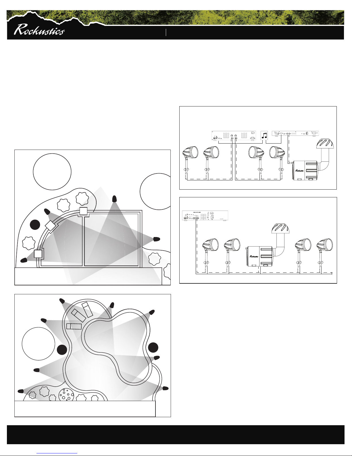
Side View
Back View
Mylar Film
Back
Red +
Black -
+
__
--
1. 2.
+