Quick Start
Original Instructions
450L GuardShield Safety Light Curtain
Catalog Numbers 450L-B4FNxYD, 450L-B4HNxYD, 450L-E4FLxYD, 450L-E4HLxYD
This quick start provides a summary of the basic steps that are required to
configure and run a system using 450L light curtains in minimal time.
Product Overview
The 450L GuardShield™ safety light curtain family is designed for use on hazardous
machinery for Point of Operation Control (POC). The product family is certified as
Type 4 electro-sensitive protective equipment (ESPE) (as defined by EN 61496-1
and IEC 61496-2) and can be used in applications that require up to and including
PLe category 4 according to EN ISO 13849-1.
The 450L safety light curtain family consists of two product lines:
• 450L-B (Basic): Suitable for basic ON/OFF applications.
• 450L-E (Enhanced): Provides enhanced features for more sophisticated
applications.
Plug-ins are available to provide for additional functions, like muting. See
publication 450L-UM001 for full specifications, details on both products, and
available accessories.
Requirements
See firmware revision information in publication 450L-UM001 for information and
the PCDC to download firmware. If you use Connected Components Workbench™
software, version 12 or later is required.
Workflow
1. Verify that you have all required parts
2. Configure the light curtain
3. Assemble, position, and mount the light curtain
4. Wire, apply power, and align system
5. Verify correct operation
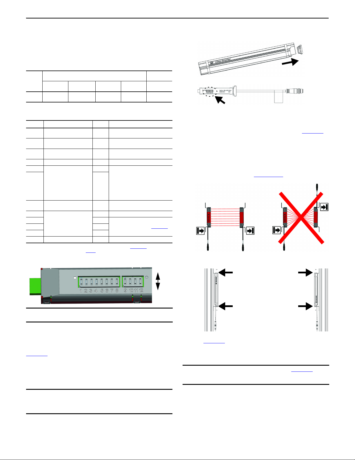
Step 1: Verify that you have all required parts
A 450L GuardShield safety light curtain is normally shipped as an individual
component (single transceiver). A functional system includes four individual boxes.
Plug-ins are ordered separately from the transceivers.
Figure 1 - Contents of the 450L Transceiver Stick Box
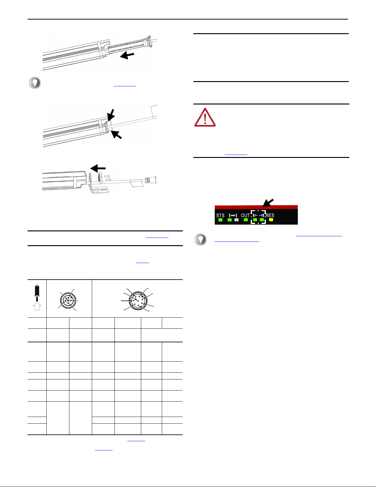
Step 2: Configure the light curtain
The plug-in that is inserted determines the functionality and operating parameters
of 450L. Configuration can be made either directly at the DIP switches or with
software:
• Connected Components Workbench software (450L-E only and requires
450L-AD-OID optical interface device).
• Studio 5000 Logix Designer® application if you use the CIP Safety model.
IMPORTANT This guide provides links to resources for more information
and is not a replacement for a complete understanding of
either publication 450L-IN004 or publication 450L-UM001.
ATTENTION: See publication 450L-UM001 for safety
application requirements and functional safety data. You must
read and understand the safety requirements before putting a
system that contains light curtains into use.
LASER LIGHT CLASS 2 HAZARD: Do not stare into the beam.
450L-E light curtains are equipped with an integrated laser
alignment help option.
Table 1 - Differences Between 450L-B and 450L-E Safety Light Curtain Systems
Description 450L-B 450L-E
Alignment
aid Two zone indicator light-emitting
diode (LED) Integrated laser alignment and two zone
indicator LED
Operating
range
• Resolution 14 mm (0.56 in.): 0.5…4 m
(1.64…13.12 ft)
• Resolution 30 mm (1.19 in.): 0.9…7.0 m
(2.95…22.97 ft)
• Reduced operating range (selected with
DIP switch):
– Resolution 14 mm (0.56 in.): 0.9…2 m
(2.95…6.56 ft)
– Resolution 30 mm (1.19 in.): 1.2…3.5 m
(3.94…11.48 ft)
• Resolution 14 mm (0.56 in.): 0.5…9 m
(1.64…29.53 ft)
• Resolution 30 mm (1.19 in.): 0.9…16.2 m
(2.95…53.15 ft)
• Reduced operating range (selected with
DIP switch):
– Resolution 14 mm (0.56 in.): 0.9…4.5 m
(2.95…14.76 ft)
– Resolution 30 mm (1.19 in.): 1.2…8.0 m
(3.94…26.25 ft)
Functionality
•Startmodes
• External device monitoring (EDM)
• Operating range
•CIPSafety™
•Startmodes
•EDM
• Operating range
•Beamcoding
•Blanking
•Muting
•Cascading
•CIPSafety
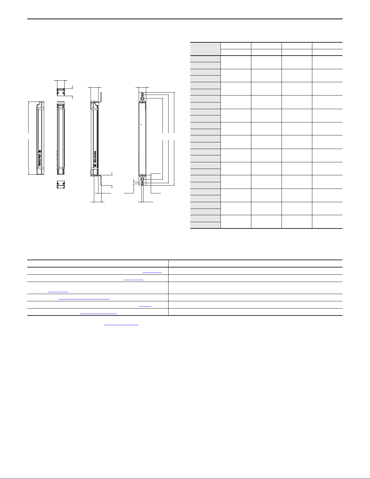
Protective
field length 150…1950 mm (5.91…76.77 in.) in 150 mm (5.91 in.) increments
IMPORTANT 450L-B transceiver stick cannot be operated with a 450L-E
transceiver stick.
Table 2 - Part List for a Complete System
Item Required
Quantity Part Description
12450L GuardShield
transceiver stick
Each box contains the following items (shown in Figure 1):
• One stick
• Mounting kit (top and bottom)
• Test rod
• Instruction manual
21Transmitterplug-in
150 mm (5.9 in.) pigtail with M12 QD connector (male)
31 Receiverplug-in
IMPORTANT Only authorized personnel must perform system
configuration, by any method.
Transceiver
Stick
Standard
Mounting Kit
Test Rod Installation
Instructions