R&S TSVP User manual

R&S®TSVP
Production Test Platform
Getting Started
1152394362
Version 07
(;ÂW[Ì)

This manual describes the following R&S®TSVP models and options:
●R&S®Compact TSVP R&S®TS-PCA3 (1152.2518.02)
●R&S®PowerTSVP R&S®TS-PWA3 (1157.8043.02)
© 2021 Rohde & Schwarz GmbH & Co. KG
Mühldorfstr. 15, 81671 München, Germany
Phone: +49 89 41 29 - 0
Email: [email protected]
Internet: www.rohde-schwarz.com
Subject to change – data without tolerance limits is not binding.
R&S® is a registered trademark of Rohde & Schwarz GmbH & Co. KG.
Trade names are trademarks of the owners.
1152.3943.62 | Version 07 | R&S®TSVP
The following abbreviations are used throughout this manual: R&S®PCA3 is abbreviated as R&S PCA3,
R&S®PWA3 is abbreviated as R&S PWA3.

1171.1307.52 - 05
1
Safety Instructions
Instrucciones de seguridad
Sicherheitshinweise
Consignes de sécurité
Risk of injury and instrument damage
The instrument must be used in an appropriate manner to prevent electric shock, fire,
personal injury or instrument damage.
●Do not open the instrument casing.
●Read and observe the "Basic Safety Instructions" delivered as printed brochure with
the instrument.
●Read and observe the safety instructions in the following sections.
Note that the data sheet may specify additional operating conditions.
●Keep the "Basic Safety Instructions" and the product documentation in a safe place
and pass them on to the subsequent users.
Riesgo de lesiones y daños en el instrumento
El instrumento se debe usar de manera adecuada para prevenir descargas eléctricas,
incendios, lesiones o daños materiales.
●No abrir la carcasa del instrumento.
●Lea y cumpla las "Instrucciones de seguridad elementales" suministradas con el
instrumento como folleto impreso.
●Lea y cumpla las instrucciones de seguridad incluidas en las siguientes secciones.
Se debe tener en cuenta que las especificaciones técnicas pueden contener
condiciones adicionales para su uso.
●Guarde bien las instrucciones de seguridad elementales, así como la
documentación del producto, y entréguelas a usuarios posteriores.

1171.1307.52 - 05
2
Gefahr von Verletzungen und Schäden am Gerät
Betreiben Sie das Gerät immer ordnungsgemäß, um elektrischen Schlag, Brand,
Verletzungen von Personen oder Geräteschäden zu verhindern.
●Öffnen Sie das Gerätegehäuse nicht.
●Lesen und beachten Sie die "Grundlegenden Sicherheitshinweise", die als
gedruckte Broschüre dem Gerät beiliegen.
●Lesen und beachten Sie die Sicherheitshinweise in den folgenden Abschnitten;
möglicherweise enthält das Datenblatt weitere Hinweise zu speziellen
Betriebsbedingungen.
●Bewahren Sie die "Grundlegenden Sicherheitshinweise" und die
Produktdokumentation gut auf und geben Sie diese an weitere Benutzer des
Produkts weiter.
Risque de blessures et d'endommagement de l'appareil
L'appareil doit être utilisé conformément aux prescriptions afin d'éviter les
électrocutions, incendies, dommages corporels et matériels.
●N'ouvrez pas le boîtier de l'appareil.
●Lisez et respectez les "consignes de sécurité fondamentales" fournies avec
l’appareil sous forme de brochure imprimée.
●Lisez et respectez les instructions de sécurité dans les sections suivantes. Il ne faut
pas oublier que la fiche technique peut indiquer des conditions d’exploitation
supplémentaires.
●Gardez les consignes de sécurité fondamentales et la documentation produit dans
un lieu sûr et transmettez ces documents aux autres utilisateurs.

Contents
R&S®TSVP
3Getting Started 1152.3943.62 ─ 07
Contents
1 Documentation Overview......................................................5
2 Installation..............................................................................7
3 Product Overview.................................................................. 9
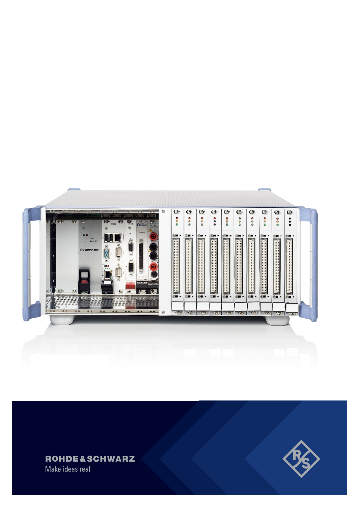
3.1 Production Test Platforms................................................................... 9
3.1.1 R&S TS-PCA3........................................................................................ 9
3.1.2 R&S TS-PWA3........................................................................................9
3.2 Software Components........................................................................10
3.2.1 R&S GTSL............................................................................................ 10
3.2.2 R&S EGTSL..........................................................................................12
3.2.3 R&S IC-Check.......................................................................................13
3.3 Test Modules....................................................................................... 14
3.3.1 R&S TS-PAM........................................................................................ 14
3.3.2 R&S TS-PICT........................................................................................14
3.3.3 R&S TS-PDFT...................................................................................... 15
3.3.4 R&S TS-PFG........................................................................................ 15
3.3.5 R&S TS-PHDT...................................................................................... 16
3.3.6 R&S TS-PIO2........................................................................................17
3.3.7 R&S TS-PIO4........................................................................................17
3.3.8 R&S TS-PIO5........................................................................................18
3.3.9 R&S TS-PIO3B..................................................................................... 19
3.3.10 R&S TS-PMB........................................................................................ 19
3.3.11 R&S TS-PSAM......................................................................................20
3.3.12 R&S TS-PSM1...................................................................................... 21
3.3.13 R&S TS-PSM2...................................................................................... 21
3.3.14 R&S TS-PSM3...................................................................................... 22

Contents
R&S®TSVP
4Getting Started 1152.3943.62 ─ 07
3.3.15 R&S TS-PSM4...................................................................................... 23
3.3.16 R&S TS-PSM5...................................................................................... 23
3.3.17 R&S TS-PSU........................................................................................ 24
3.3.18 R&S TS-PSU12.................................................................................... 25
3.4 In-System Calibration......................................................................... 25
4 GTSL download from GLORIS............................................27
4.1 New in GLORIS? Learn how to register............................................27
4.2 Download Area....................................................................................28
4.3 Which Version of GTSL should I install on my TSVP System?...... 30
5 Contacting Customer Support........................................... 32

Documentation Overview
R&S®TSVP
5Getting Started 1152.3943.62 ─ 07
1 Documentation Overview
This section provides an overview of the R&S TSVP system user documentation.
The user documentation includes operating manuals, technical information and
data sheets for the base units R&S CompactTSVP and R&S PowerTSVP, plus
associated measurement modules as well as a service manual as PDF files.
All documents are delivered with the Generic Test Software Library ("R&S GTSL")
installation package. After installing the software, you can open all the documen-
tation from the Windows start menu. Additionally you can find detailed information
about the call interfaces in the "R&S GTSL Help" folder of Windows start menu.
The user documentation and "R&S GTSL" installation package are also available
for download in Gloris.
https://gloris.rohde-schwarz.com/
Getting started manual
Introduces the R&S TSVP system and describes how to set up and turn on the
products. A printed version is included in the delivery.
System manual
Contains information about the system and its hardware and software compo-
nents, including installation instructions and use case examples.
User manuals
Describe the features and functions of the system components. They also pro-
vides information on maintenance, instrument interfaces and error messages.
User manuals are available for all system components (hardware and software).
Service manual
Describes the performance test for checking the rated specifications, module
replacement and repair, troubleshooting and fault elimination, and contains spare
part lists.
Basic safety instructions
Contains safety instructions, operating conditions and further important informa-
tion. A printed version is included in the delivery.

Documentation Overview
R&S®TSVP
6Getting Started 1152.3943.62 ─ 07
Data sheet
The data sheet contains the technical specifications of the system. It also lists the
options and their order numbers as well as optional accessories.
Release notes and open source acknowledgment
The release notes list new features, improvements and known issues of the cur-
rent firmware version.
The open source acknowledgment document provides verbatim license texts of
the used open source software.

Installation
R&S®TSVP
7Getting Started 1152.3943.62 ─ 07
2 Installation
Before putting the unit into operation for the first time, be sure to read and
observe the important safety and operating instructions supplied in the operating
manual.
If the software is not already installed, read the readme.txt file in the main
directory of the software package to determine the requirements and the proce-
dure for installing the software.
If your CompactTSVP is equipped with an internal system controller, you can put
the instrument into operation as follows after connecting a monitor, keyboard and
mouse:
1. Switch on the R&S TSVP at the rear.
2. Log on under Windows (no password!).
3. Start the "R&S GTSL TSVP Self Test" in Windows start menu. Details of the
self-test are described in the "Service Manual CompactTSVP and Pow-
erTSVP".
If your CompactTSVP should be controlled by an external computer with help of a
compact PCI bridge solution, you can put the instrument into operation as follows:
1. Install the R&S GTSL package on your computer. See "R&S GTSL Software
Description" for details.
2. Install the bridge module into your computer. Refer the appropriate manual
how to install the PC card and how to connect the components.
3. Connect the CompactTSVP to the computer.
4. Power on the CompactTSVP first.
5. Power on your computer.
6. Start the R&S GTSL "Instrument Soft Panels" application from the start menu.
All installed TSVP modules should be listed in the main window. In the "Tools"
menu use the option "Create Physical.ini…" to automatically generate the
configuration file. See "R&S GTSL Software Description" for details.
7. Start the "R&S GTSL TSVP Self Test" application from the Windows start
menu. Details of the self-test are described in the "Service Manual Com-
pactTSVP and PowerTSVP".

Installation
R&S®TSVP
8Getting Started 1152.3943.62 ─ 07
The selftest checks whether the instrument is operating properly.
The SFT report is stored on Windows XP systems in the file
C:\Program Files\Rohde&Schwarz\GTSL\SFT_Report.txt.
On Windows 7 systems you can find the report in
C:\Rohde&Schwarz\GTSL\SFT_Report.txt.
On Windows 10 systems you can find the report in
C:\Users\Public\Public Documents\Rohde-Schwarz\GTSL.
In case of problems concerning the software or hardware installation, the chapter
"Installation of R&S CompactTSVP and R&S GTSL" of the "R&S System Manual
TSVP" may help. It describes known issues along with possible solutions.

Product Overview
R&S®TSVP
9Getting Started 1152.3943.62 ─ 07
3 Product Overview
3.1 Production Test Platforms
3.1.1 R&S TS-PCA3
The Test System Versatile Platform R&S CompactTSVP is a standardized modu-
lar platform for the program-controlled testing of modules and terminals in the fac-
tory or laboratory. With its flexible configuration and the use of worldwide stand-
ards, it can be perfectly adapted to suit the needs of the user. Larger ATE (Auto-
matic Test Equipment) systems can be created by combining R&S CompactTSVP
(TS-PCA3) and PowerTSVP (TS-PWA3). The production test platform is intended
for use with a control processor which performs the test on the test devices by
means of peripheral modules. This control processor is known as the system con-
troller and should preferably be in the R&S CompactTSVP. However a standard
PC can also be used running across a suitable interface with the controller. The
system controller executes user-created sequences that define the test proce-
dures and specification limits. The modules plugged into the R&S CompactTSVP
can be used for the creation of test and control signals and for the measuring
related evaluation of the response from the UUT. For this purpose they are able to
pass signals between each other and select signals under program control and
pass them to external measuring systems. The peripheral modules can be quickly
and flexibly adapted to the test devices by preceding the R&S CompactTSVP with
an adapter frame which connects the signals securely and with a low rate of wear.
If the production test requires switching functions with a large number of channels
or the switching of high currents, then the R&S CompactTSVP can be supple-
mented with a PowerTSVP. The R&S PowerTSVP is controlled via the CAN-Bus
of the R&S CompactTSVP.
3.1.2 R&S TS-PWA3
The R&S PowerTSVP is primarily intended as a flexible switching unit for mea-
surement signals, signal sources and UUT loads. This facilitates the migration of
existing and proprietary "Rack and Stack" systems to a production test platform.
Production Test Platforms

Product Overview
R&S®TSVP
10Getting Started 1152.3943.62 ─ 07
The R&S PowerTSVP can be fitted with special ROHDE & SCHWARZ switching
and load modules. The unit provides an analog bus that can be used to make
complex connections. The modules can also be used without any modification in
the R&S CompactTSVP.
3.2 Software Components
3.2.1 R&S GTSL
The Generic Test Software Library R&S GTSL is a collection of libraries for spe-
cific test tasks like measurements, switching and signal generation. An ASCII file
contains the relevant configuration data which can be assigned to certain test
sequences. So measurement parameters can be changed and adjusted easy and
quickly with a standard editor.
An arbitrary test sequencer software may be used to control the test sequence.
This software combines the individual test sequences to form an executable test
program. It also adds all other functions important to the production operation,
such as user administration, execution of multiple test sequences in multi-thread-
ing or parallel operation, collection and storage of relevant measurement results
and report generation.
The lowest level of the R&S GTSL accommodates the device drivers needed for
the hardware used (Device Driver Layer). These include the device drivers for
●the hardware developed and used by ROHDE & SCHWARZ.
●the standard hardware used.
The middle level of the R&S GTSL accommodates the different test libraries
(Library Layer). These test libraries provide the functions needed to execute test
sequences.
GTSL Test Libraries
●AUDIOANL.DLL, Audio Analysis
Used for RMS calculation, frequency calculation, distortion, filter- and compa-
rator analysis
●DCPWR.DLL, DC Power Supply
Software Components

Product Overview
R&S®TSVP
11Getting Started 1152.3943.62 ─ 07
Used for R&S TS-PSU and power supplies with IVI compliant device drivers
and for control of internal and external power supply units
●DIOMGR.DLL, Digital I/O Manager
Used for R&S TS-PDFT, R&S TS-PIO3B, TS-PIO4, TS-PIO5 and modules
using „IVI digital“ compliant device drivers.
Allows the creation of digital i/o bus topologies including more modules and a
digital pattern configuration
●DMM.DLL, Digital Multi-meter
Used for R&S TS-PSAM and devices using „IVI DMM“ compliant device driv-
ers Allows the configuration and execution of analogue measurements (DCV,
ACV, DCC,ACC, resistor)
●FUNCGEN.DLL, Function Generator
Used for R&S TS-PFG and devices using „IVI generator“ compliant drivers
Allows the creation of usual signals as sine, rectangle, triangle, the creation of
arbitrary waveforms and the handling of sequences
●SIGANL.DLL, Signal Analyzer
Used for R&S TS-PAM and devices using „IVI scope“ compliant drivers
Allows the creation of WFA measurements and the readout of data and mea-
surement results
●RSMGR.DLL, Resource Manager
Used for adminstration functions for any hardware defined in the
PHYSICAL.INI file
●ROUTE.DLL, Signal Routing
Used for supporting functions for complex path management
Includes any switching module
NOTE:
Not in combination with SWMGR.DLL
●SWMGR.DLL, Switch Manager
Used for supporting functions for switching of single paths at single modules
NOTE:
Not in combination with ROUTE.DLL
●ICT.DLL and ICCHECK.DLL, In-Circuit Test
Used for supporting functions for In-Circuit and IC-Check test methods
●FTBLIB.DLL, Factory Toolbox
Used for supporting functions for R&S TS-PIO3B and extensions
●SFT.DLL, Self Test Support
Used for controlling functions for the execution of TSVP modules self test
Software Components

Product Overview
R&S®TSVP
12Getting Started 1152.3943.62 ─ 07
●TOOLKITTESTSTAND.DLL, Toolkit TestStand
Used for supporting functions for test sequencer "TestStand" from National
Instruments Corp.
●OPERINT.DLL, Operator Interface
Offers a configurable "TestStand" operator interface
3.2.2 R&S EGTSL
The Enhanced Generic Test Software Library R&S EGTSL is part of an extension
to the Generic Test Software Library R&S GTSL. Using R&S EGTSL it is possible
to prepare and perform in-circuit tests. The individual R&S EGTSL software com-
ponents are arranged in individual layers exactly like R&S GTSL. The bottom
layer (device driver layer) of the R&S EGTSL contains the device drivers neces-
sary for the test hardware used. The test hardware is accessed using these
device drivers. The middle layer (library layer) of the R&S EGTSL contains the
ICT test library and the R&S EGTSL runtime library. The ICT test library provides
the functions necessary for performing the in-circuit test. Using the R&S EGTSL
runtime library (runtime engine) the internal R&S EGTSL program processes are
run. In this layer further information is passed to the resource manager library via
the two files PHYSICAL.INI and APPLICATION.INI. The various device driv-
ers from the lowest level are called from this layer. The top layer (execution layer)
contains the test sequences for performing the in-circuit test. The test sequences
call functions from the ICT test library in the middle layer. The function calls
include, e.g.
●loading ICT programs,
●running ICT programs,
●debugging ICT programs and
●the generation of reports.
The calls for the individual functions from the ICT test library can, e.g., be made
using a sequence editor (TestStand) or a dedicated C program. The top layer
(execution layer) also contains the R&S EGTSL Loader and the R&S EGTSL user
interface (R&S EGTSL IDE). The R&S EGTSL user interface (R&S EGTSL IDE)
is opened using the R&S EGTSL runtime library either by the R&S EGTSL
Loader or a function call from the ICT test library.
Software Components

Product Overview
R&S®TSVP
13Getting Started 1152.3943.62 ─ 07
3.2.3 R&S IC-Check
Using Generic Test Software Library R&S IC-Check it is possible to prepare and
perform tests on pins of ICs or other mounted electronic circuit devices. The indi-
vidual R&S IC-Check software components are arranged in layers exactly like
R&S GTSL.
●The bottom layer (device driver layer) of the R&S IC-Check contains the
device drivers necessary for the test hardware used. The test hardware is
accessed using these device drivers.
●The middle layer (library layer) of the R&S IC-Check contains the R&S GTSL
IC-Check library. The R&S IC-Check library provides the functions necessary
for performing the IC-Check tests.
In this layer further information is passed to the resource manager library via
the two files PHYSICAL.INI and APPLICATION.INI. The various device
drivers from the lowest level are called from this layer.
●The top layer (execution layer) contains the test sequences for performing the
IC-Check tests. The test sequences call functions from the R&S IC-Check test
library in the middle layer. The function calls include, e.g.
– loading ICC programs
– running ICC programs
– debugging ICC programs
– generating reports
The calls for the individual functions from the R&S IC-Check test library can
be made using a sequence editor (e.g. TestStand) or a dedicated C program.
The top layer (execution layer) also contains the R&S IC-Check Loader and
the R&S IC-Check User Interface which is opened using a function call from
the R&S IC-Check test library.
R&S IC-Check includes the following parts and programs:
●R&S IC-Check test library
●R&S IC-Check Loader
●R&S IC-Check User interface
Software Components

Product Overview
R&S®TSVP
14Getting Started 1152.3943.62 ─ 07
3.3 Test Modules
3.3.1 R&S TS-PAM
The R&S TS‑PAM waveform analyzer module is a CompactPCI/PXI module that
takes up one slot in the R&S CompactTSVP test system versatile platform.
It offers the following key features:
●Two separate „floating“ inputs
Each input can be split into 8 (single) / 4 differential measurement channels
Input range : +/- 0.2 V to + / - 100 V (max. 125V)
●14 - Bit ADC resolution; 20 Msamples/s; samplerate for 2 channels 2 x 1
Msample sample memory depth
●Usable like a digital oscilloscope
●Trigger modus selectable: software, edge ,sample
Each R&S TS-PAM module can only be used in the R&S CompactTSVP
and requires a R&S TS-PDC at the assigned rear I/O slot.
3.3.2 R&S TS-PICT
The ICT Expansion Module R&S TS-PICT is a universal expansion module for
the R&S CompactTSVP (Test System Versatile Platform). In combination with the
R&S TS-PSAM measuring module and the R&S EGTSL software, the module is
used for the realization of in-circuit measurements.
It offers the following key features:
●Testing of resistors,capacitors,inductors, diodes and transistors
●Resistor, inductor, capacitor measurments with „guarding“ (3- , 4-, 6- wire con-
nections supported)
●Measurement ranges:
– 0.1 Ω - 10 MΩ DC (2- and 4-wire connections + “guarding“)
– 0.2 V to 5 V
– 100μA to 100mA source settings
Test Modules

Product Overview
R&S®TSVP
15Getting Started 1152.3943.62 ─ 07
The R&S TS-PICT module can only be used in the R&S CompactTSVP and
only in combination with the R&S T-PSAM module. It requires a R&S TS-
PDC at the assigned rear I/O slot.
3.3.3 R&S TS-PDFT
The Digital Function Test Module R&S TS-PDFT is for use wherever simple or
complex digital circuits are tested or programmed by static or dynamic stimula-
tion/recording/ communication.
It offers the following key features:
●Output
– 32 digital output channels in 4 groups and 8 bit/group configurable
– Output voltage : -3V to +10 V configurable in 4 groups and 8 bit/group
– TTL mode: 0.8V / 2.5V / 3,3V volt up to 80 mA current per channel
– Sample rate max. 20 MHz with 25 ns Resolution
●Input
– 32 digital input channels in 4 groupes and 8 bit/group configurable
– Input voltage: -5 V to +12 V
– Availbale input modes: hysteresis and comparator
– Sample rate max. 20 MHz with 25 ns resolution
– Input protection: max. ± 42 V
The R&S TS-PDFT module can only be used in the R&S CompactTSVP.
3.3.4 R&S TS-PFG
The Function Generator Module R&S TS-PFG can be used wherever single or
multiple channel analog output signals have to be simulated.
It offers the following key features:
●Two floating Outputs
●AC 1 Hz to 1 MHz, DC-mode possible (DC - Source mode)
●± 20 V Output voltage, can be cascaded up to ± 40 V
Test Modules

Product Overview
R&S®TSVP
16Getting Started 1152.3943.62 ─ 07
●Output current:
–≤500 kHz, max. 250 mA
– 500 kHz to 1 MHz, max. 125 mA
●Pre-defined output waveforms
– sine
– triangle
– rectangle
●Arbitrary function: DC, 1 Sample to 25 Msamples/second, Resolution: 40 ns
Each R&S TS-PFG module can only be used in the R&S CompactTSVP
and requires a R&S TS-PDC at the assigned rear I/O slot.
3.3.5 R&S TS-PHDT
The High-Speed Digital Test Module R&S TS-PHDT is used wherever digital cir-
cuits are tested by static or dynamic stimulation and the response is recorded.
It offers the following key featues:
●32 output channels, high and low level for each port (8 channels), separately
adjustable
●Output level range -3 V to +10 V
●Maximum output current per channel 80 mA
Maximum output current per port:
– 500 mA for output level ≤ 2.9 V
– 200 mA for output level > 2.9 V
●Current limiting for high and low level, separately adjustable for each port
●Each channel is individually switchable to "Tri State" at the maximum pattern
rate
●High-level is formattable within the pattern duration (return-to-zero) 32 input
channels, high and low limit for each port, separately adjustable
●Maximum pattern rate 40 MHz
●Memory depth 64 Mpattern
Test Modules

Product Overview
R&S®TSVP
17Getting Started 1152.3943.62 ─ 07
The R&S TS-PHDT module can only be used in the R&S CompactTSVP.
3.3.6 R&S TS-PIO2
The R&S TS-PIO2 analog and digital I/O module is a 16-channel stimulus and a
16-channel parametric measurement unit for versatile DUT testing. It is part of the
R&S TSVP modular test and measurement platform and makes full use of the
common analog measurement bus and the standardized isolated front-end tech-
nology.
It offers the following key features:
●16 input channels and 16 output channels
●Output voltage range ±27 V
●Input voltage range ±7 V, ±14 V, ±28 V
●Maximum output current for the 12 standard channels 25 mA, 100 mA for the
extended channels
●24 bit resolution
●Maximum sampling rate during measurement and update rate for output 5
kHz
●Memory for 4 x 5000 values (analog and digital measurement values; digital
bit pattern and arbitrary waveform output)
Each R&S TS-PIO2 module can be used in R&S CompactTSVP and R&S
PowerTSVP and requires a R&S TS-PDC at the assigned rear I/O slot.
3.3.7 R&S TS-PIO4
The R&S TS‑PIO4 digital functional test module can be used in all test and mea-
surement scenarios where simple or complex digital circuits have to be tested
using static or dynamic digital patterns. It is intended for the R&S CompactTSVP
test platform. The module is controlled by the CompactPCI bus.
It offers the following key features:
●32 digital inputs and 32 digital outputs divided into 8 ports each with 4 chan-
nels
Test Modules

Product Overview
R&S®TSVP
18Getting Started 1152.3943.62 ─ 07
●Programmable output level range from ‒6 V to 10 V, output impedance 30 Ω
(typ.)
●14 bit resolution
●Output current up to 150 mA per channel, 350 mA per port
●Two programmable input thresholds per port for hysteresis or level monitoring
●Pattern rate up to 40 MS/s per channel x 12.5 ns resolution
●Memory depth 2 Msample (32‑bit data)
●Synchronization/triggering via PXI trigger bus and via XTI (TTL)
3.3.8 R&S TS-PIO5
The R&S TS‑PIO5 digital LVDS functional test module is used wherever digital
circuits are tested by flexibly programmable static or dynamic stimulation and the
response is recorded. Bidirectional LVDS, LVTTL and RS485 transceiver chan-
nels are available for this purpose. It is intended for the R&S CompactTSVP test
platform. The module is controlled by the CompactPCI bus.
It offers the following key features:
●Two MDR connectors, each with 10 LVDS channels (8 data, 1 universal chan-
nel, 1 clock)
LVDM bidirectional, terminated with 100 Ω
●2 LVTTL signals per MDR connector
●+5 V / max. 0.30 A available at every MDR connector, protected by fuse and
diode
●10 RS485 transceiver channels available via a contact strip on the board
●Sample rate up to 200 Msample/s
●Maximum resolution 5 ns
●Memory depth 2 Mpattern (32 bit)
– 10 bit RS485
– 4 bit LVTTL
– 18 bit LVDS
●Synchronization/triggering via
– PXI trigger bus
– SMB clock/trigger input and output
– PXI 10 MHz clock
Test Modules
Table of contents
Other R&S Test Equipment manuals