General International 40-350 User manual

MOTOR M1 5 HP, 220V, 1 PH 60HZ.25A
WEIGHT 748 IBS (340 Kg)
Heavily ribbed, solid cast iron table with a smooth ground
surface finish.
Four(4) spindle speeds with reverse.
Independently adjustable left and right industrial duty
fences with precision fine-tune adjustment dials.
Deluxe precision T-slot miter gauge for better workpiece
control.
5HP industrial motor protected against dust by a totally
enclosed cabinet.
Magnetic switch with thermal overload protection.
Quick release belt tensioning system for quick and easy
speed changes.
Built-in caster system for instant mobility within the shop.
Large cutter guard with window, spring hold down and
built-in 4” dust outlet.
Convenient, extra large adjustment handles.

lighting is available. - .
before cutting.
designed.
contacted.
14. Do not force the machine. It will do the job better
and be safer at a rate for which it was designed.
15. Keep guards in place and in working order. If a guard
must be removed for maintenance or cleaning make
removed before turning power on.
with three-prong plug, it should be plugged into a
three-pole electrical receptacle. Never remove the
third prong.
19. Always disconnect tool before servicing and when
changing accessories such as arbors or cutters.
21. Hold material firmly against the table.
GENERAL ® INTERNATIONAL guarantee
All component parts of GENERAL INTERNATIONAL machinery are carefully inspected during all production stages and each
machine is thoroughly Inspected upon completion of assembly. Because ofquality, GENERAL INTERNATIONAL agrees to
within a period of 24 months from date of purchase.ln order to obtain warrantee, alldefective parts must be returned prepaid
to GENERAL INTERNATIONAL MFG. Co Ltd. Repairs made without our written authorization voids all guarantees.

1. GUARD
2. FENCE
3. SAFETY GUARD
4. KNOB
5. SCREW KNOB
6. WASHER
7. RETAINER (L)
8. RETAINER (S)
9. PLATE GUARD
10. TENSION
11. WRENCH
12. BAR
13. MITER GAUGE
14. MITER GAUGE FENCE
15. SPINDLE
16. WRENCH
17. WRENCH
18. ADJUSTMENT HANDLE
19. KNOB
20. WRENCH
21. DRAWER BAR
22. WASHER
1
2
3
4
9
5
10
1415
17
8
18
16
12
11 13
6
7
19
20
21
22

inspected
before shipment and if properly used will give perfect results, However, a reasonable
amount of care and attention is necessary to ensure perfect performance and accurate
work. It is imperative that you take a few moments to familiarize yourself with these
instructions, as they will no doubt save you a lot of
UNPACKING AND CLEANUP
and install it accurately before use. As soon as you receive
the shaper, we recommend you follow these procedures:
1. Finish removing the contents of the shipping wooden case and compare with the
contents list.
3. Clean all rust protected surfaces with a mild solvent or kerosene. Do not use lacquer
thinner; paint thinner, or gasoline. These will damage painted surfaces. -
4. To prevent rust, apply a light coating of paste wax to surface.
INSTALLATION
1. Machine must be placed on a flat, solid surface.
2. Remove all foot bolts locking it to its shipping base before lifting machine.
4. Test machine length-wise and cross-wise before starting any operations.
5. Metal shims must be placed under low corners.
6.Once all four corners are supported, tighten lag screw, and retest machine in both
directions.
POWER CONNECTIONS
The spindle shaper has been factory wired before shipment. Before connecting to the
power source, verify that power outlet corresponds with the motor voltage. All electrical
and motor wiring must be performed by a qualified electrician. This machine must be
properly grounded while in use for protection against electrical shock.
E
LECTRICAL CONTROLS
button, magnetic control system, and
a
reverse switch.(Fig. 1,2)
A
B
C
FIG.1

S
PEED CHANGE AND BELT ADJUSTMENT
F
ollow these procedures to change speed and
a
djust the proper belt tension.
1
. Disconnect machine from power source.
2
. Open guard door.
4
.Move the belt to the other groove (Fig. 3B)
5
.Push handle bar (Fig. 3C) to get proper belt tension
6
. Tighten the lock handle.(Fig. 3A)
7
. Close guard door.
S
PINDLE RAISING AND LOWERING: (FIG. 4. 5)
P
rocedures to adjust the main shaft in the up or
d
own position.
1
. Hand wheel (A) must be loosened. '
3
. Hand wheel (A) must be tightened.
S
PINDLE CHANGE
1
-1/4" spindle assemblies are supplied with your
s
haper. The assemblies are locked in a tapered seat
w
ith a draw bar and nut.
C
HANGING
O
ne wrench must be placed on the flats on top of
h
e spindle and the second wrench on the draw bar
n
ut (Fig. 6), this allows the spindle to
T
urn the nut two times; tap gently upwards with a
w
ooden block, this will loosen the spindle from the
a
per. Remove nut and lift out the spindle.
FIG.2
A
FIG.3
C
B
FIG.4
FIG.5
A
B

SQUARING THE FENCE
Occasionally the aluminum fence will have to be squared with the mounting surface and
adjusted parallel to each
2. The wing screw (C) should be tightened to hold the aluminum fence (B) securely.
. The fence should now make contact with the jointed edge and
square with the table.
CHANGING CUTTERS
All spindle sizes are equipped with a safety lock nut, Left-
hand threads
are found above the large spindle nut. (Fig.7) To mount
or change
cutter, first remove the safety lock nut. :
Remove the spindle nut by placing one wrench on the
spindle nut and another wrench on the flats on top of the
spindle. Safety lock nut must be replaced before starting
work operations.
TABLE INSERT
The second table insert has a guide shoulder of Ø3-1/2",
this table Insert is used for copying. :
ASSEMBLING AND INSTALLING SHAPER FENCE
The fence can be assembled using the diagram (pg.22) as
a guide. Fence installation: Once assembled, place the
fence on the table. Lock it in place using the two-lock
handles (A) and two-lock levers (B). (Fig.9)
(
SPINDLE
SAFETY LOCK NU
T
SPINDLE NUT
SPACER
FIG.6
FIG.7
FIG.8
FIG.9
A
B

OPERATING CONTROLS FOR THE FENCE
Depending on the type of work you are shaping, either side of the fence can be moved
freely. Fence can be moved by loosening wing screws (A),(Fig.11) Proper setting can be
achieved by turning knob (B). The turning knob (B) is with scale for accurate setting.
Wing screws (A) must be then tightened to fix in position.
Each fence half should be adjusted as close to cutter head as possible.
WORK SAFETY HOLD DOWN ADJUSTMENT
Loosen knob (A), turn tension plate to desired angle. Then tighten the bolt. (Fig. 13,14).
FIG.10
B
A
B
A
FIG.11 FIG12
A
B
D
C
A
E

PROTECTION GUARD ADJUSTMENT (FIG. 15)
1. Loosen two knobs (A) to slide protector to desired
height.
PERIODICAL MAINTENANCE
Experienced technician should be contacted when the ball
bearings
• Spindle must always be cleaned properly and with care, with the
use of compressed air jet.
• Make sure never to apply oil to the belts and the pulleys, clean
with a dry soft rag to clean when greased or dirty.
• V-belt must never be under excessive strain, this will cause the machine to overload and can damage
the motor bearings, spindle and belt.
A
FENCE ADJUSTMENT (FIG.16)
The fence is fixed the position before shipment, following the
instruction for when need to do the minor fence adjustment.
1. Loosen the screw (A) and adjust (B) set screw for adjusting
the fence to proper position then tighten screw (A). (Pic.1)
2. Loosen the screw (A) and adjust (D) set screw for adjusting
the fence to proper position then tighten screw (A). (Pic.2)
1. Loosen the screw (A) and adjust (E) set screw for adjusting
the fence to proper position then tighten screw (A). (Pic.3)
2. Loosen the screw (A) and adjust (C) set screw for adjusting
the fence to proper position then tighten screw (A). (Pic.4)
FIG.15
FIG.16
B
MACHINE LEVELING
Shift the foot pedal (A) upward to allow the leveling
screw (B) and four leveling screws located at the four
bottoms to rest on the floor.
Shift the foot pedal (A) downward to fixing the machine.
Turn the four leveling screws by using open end
wrench for adjusting the machine leveling.
A
FIG.17
B
A
E
C
D
fence
bracket
fence
bracket
Improper position

1. Spacers, cutters and collars mounted on the spindle shaft must be in a fixed position. There must be
no movement, space or touching between parts.
2. Counter bores and holes of collars, cutters or spacers must be in perfect condition with no rust or
flaws.
BEFORE OPERATING
The main drive motor should run for a few seconds, to make sure that it is performing in the proper
rotation. Looking down at the spindle, it should be rotating counter-clockwise this is the proper position.
Machine should stay on for a short period of time to make sure that all moving parts are properly
positioned with no excessive vibration. If any adjustments are required disconnect machine from the
power source before properly adjusting.
WARNING !
ALL WORK OPERATORS MUST READ AND
UNDERSTAND
THE MANUAL BEFORE STARTING ANY
WORK
OPERATIONS ON THE SHAPER !
« ATTENTION !
work piece must be fed from right to left.
work piece must be fed from left to right.
CUTTER ROTATION

GRAIN DIRECTION
The work piece should always be shaped in the same direction as the grain (if possible). When
cut against the wood grain, woods as redwood, fir and oak will leave a rough, or slightly
splintered edge.
CAUTION: When deep cuts are required, they will need strong power and a pushing force in
order to control the cut. Deep cuts can also cause the wood to split or splinter, this may lead to
loss of control or injures to the work operator. When a finished edge is not to your satisfaction,
cut a few more times with no more than 1/16" deep. Pre-cut stock on band saw 1/16" whenever
possible.
The trailing board edge will splinter when shaping across the grain. The best solution would be
to cut the board 1 /4" oversize in width shape the board and simply trim off the excess.
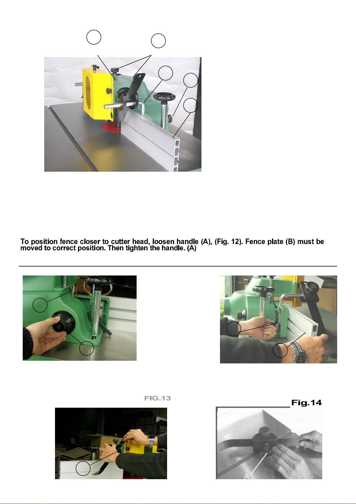
STRAIGHT EDGE SHAPING •
The work piece must always be against the fence to
perform straight edge shaping, follow these procedures to
set up:
1. Disconnect machine from the power source.
2. Fence faces must be parallel, properly in line or offset If
necessary,
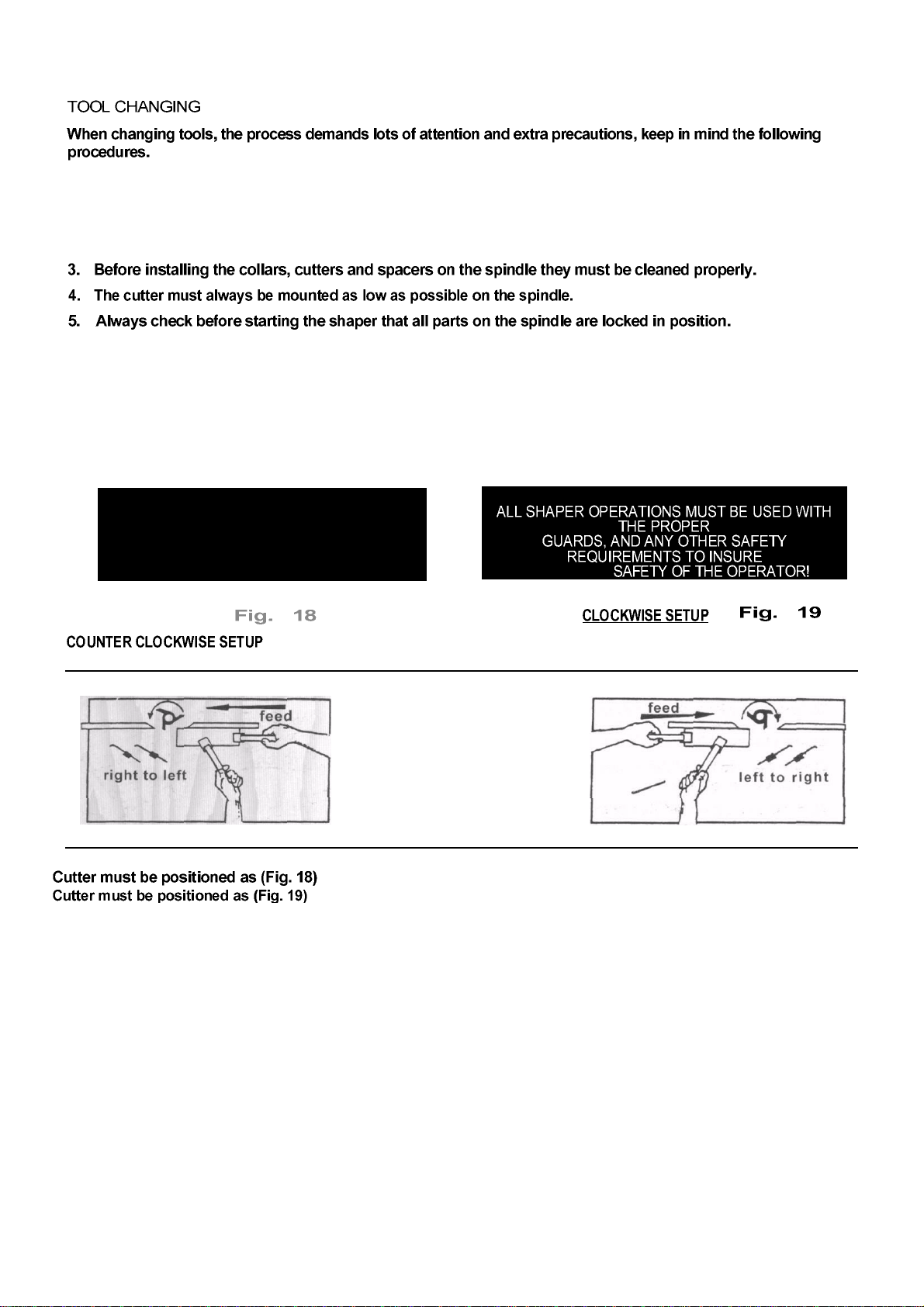
3. Cutter must be rotated and inspected for clearance.
4. Position the leading face of a cutter head blade at 90
degrees to the infeed fence and adjust the spindle to
the desired height of the cut. At the same time check
the desired depth of cut with the blade in the 90
degrees position.(Fig. 20)
DEPTH OF CUT
The depth of cut is the distance from the outside circumference edge of the collar which the
work rides against to the outside edge of the cutter. The depth of the cut is determined by the
position of the fence relative to the cutter head or by the use of shaper collars.
1. Spindle must be locked.
2. Right guard should be installed wherever possible.
3. Connect to the power source.
Note: To determine if the cut, profile and depth are correct you will only need a short cut.
5. Make adjustments if required, or proceed shaping using the work piece.
EDGE SHAPING: LONG BOARDS
The work piece must be at least 12 inches long when edge
shaping long boards.
1. To hold work piece down and against the fence use the
hold -downs and horizontal clamps. If the work piece is too
wide for the horizontal clamps(Fig. 21), clamp a scrap board to
the table to keep the work piece against the fence.
3. To make a smooth cut the work piece should be fed slowly
and steadily with firm, even pressure. Note: The rate feed depends
on depth of cut and experience of operator.

EDGE SHAPING: SHORT BOARDS
When edge shaping short boards, never attempt to hand guide any
stock less than 12 inches long, or narrower than 3 inches without the use
of a special guide (Fig. 22)
END SHAPING
When end shaping narrow stock at least one half of the work piece
end must be in contact with either the outfeed or infeed fence. (Fig.
23)
Warning: never attempt to shape a narrow piece without a special
guide, the work piece may star rocking into the cutter head
causing minor or major injury to the work operator.
SHAPING SIDES
When shaping across the grain, some woods
are more likely to chip out or splinter. It is
recommended to shape cross grain sides first.
Any chipping that does occur will be removed
by the subsequent cut with the grain. (Fig. 24).
Using the existing bolts in the fence, attach a
taller shop-made fence when the shaper fence
does not support firmly support taller stock,
(Fig. 25)
Note: To avoid interference with mounting
screw, make sure the bolt holes are on your
shop-made tall fence are countersunk.

SHAPING CONTOURED EDGES WITH RUB COLLARS
To shape contoured edges the fence assembly should
be removed. In order to control the work piece and
limit the depth of cut an anti-friction collar must be
used.(Fig, 26)
The purpose of the collar is to ride against the work
piece, collar can be positioned above or
below the cutters. The ring guard should be used
whenever possible.
When work piece needs to be shaped alt around the
perimeter, hold firmly and press the work straight into
the cutter until the collar established depth of cut.
While holding firmly, keep feeding the work so the
point of contact on the edge is always 90 degrees to
the collar.
When work piece is not contoured all around, start the
cut as shown in (Fig. 29).
WARNING i
12" AWAY FROM ANY CUTTING
DEVISES.
Small size materials need a special shaping jig. (Fig. 30)
Remove entire fence assembly; place jig carefully at the
desired depth of cut, clamp to table securely. It is
important with arc and circle shapes that the work piece
must be roughly cut to desired size and curve of the
finished piece, before being shaped. The curve of the jig
must match the work The work piece must
be firmly attached to the jig.
This operation should always be in use of a ring guard or a
similar safety device over the cutter head.
anti-friction
collar
at least
workplace

ENCLOSED EDGE SHAPING
Inside edge work piece are shaped the same way as
outside edges (Fig.31). When the whole edge needs to be
shaped, the operator must use
The work piece must be placed on table before starting the
motor. The operator must shape the whole work piece by
feeding into the cutters.
WARNING !
NEVER ATTEMPT TO PERFORM THIS
PROCEDURE WITHOUT A
RING GUARD OR A SIMILAR SAFETY
DEVICE OVER
CUTTERHEAD ! ATTENTION !
OPERATION MUST BE AWARE AT ALL
TIMES OF THE FEED DIRECTION !
OPERATION MUST NOT BE LEFT
UNATTENDED!
1. Use a firm grip to ease the edge into the cutters until
stopped by the collar (Fig. 32).
2. Keep pushing straight while turning and feeding the
work piece, continue until the cut
the off position and remove the work
piece only once the cutters have
NEVER PERFORM ENCLOSED EDGE SHAPING WHEN
THERE IS LESS THAN 12" OF WOOD MATERIAL ALL
AROUND THEOPENING ! THE ONLY TIME THIS CAN BE
DONE IS IF THE WORK PIECE IS ATTACHED TO A
LARGER WOOD BASE!
TEMPLATES
A template serves as guide for the cutter. The
template must be made a
collar, recommended size 3/4". (Fig. 33)
MULTI-PIECED TEMPLATES
workplace
tem
p
late
ATTENTION !
NEVER PERFORM ENCLOSED
HAPING WHEN WORK PIECE
OPENING IS MALLER THAN TWICE
THE DIAMETER IN ANY
DIRECTION

SECURING A TEMPLATE TO THE WORK PIECE
Various methods are used to secure template to the
work piece. The operator should select the best
method to secure the template to the work piece
based on
piece is large enough to surpass the
front of table, while still leaving space for the desired
cut. (Fig, 35)
The work piece may be placed against the template
using dowels as work piece
through the cut. (Fig. 36)
HORIZONTAL TOGGLE CLAMP
Horizontal toggle clamp are useful when the regular
"C" clamps cannot allow the freedom of movement
required in shaping (Fig. 37). No additional hand
pressure is necessary for the operator to control the
work piece. Anchor points like dowels are necessary
with this setup.
PROTECTION workplace
The operators should take precautions to protect
themselves, and all others around the work area and
the machine itself for improper use.
Never leave machine unattended while it is running,
the operator needs to be very focused and attentive,
and not looking elsewhere or carrying on
conversation while using the machine. Carelessness
or inattention will result in serious injuries and
damages.
SPECIAL CUTS
the cutters. The most efficient
cutters are carbide tipped to ensure cleaner cuts and
longer cutter life. Small cutters may be solid carbide,
some use inserts. Since there is such various choices,
the operator is limited only
cutter

STACKED CUTTERS
A variety of timesaving and interesting cuts can be
made in a single setup by stacking the cutters (Fig.
39). When stacking cutters extra care should be taken.
Check that cutters have no flaw nicks, or just. Cutters
must cleaned and perfectly balanced before placing in
the stacked poisiton.
SASH AND DOOR SHAPING
Door shaping requires two
operations. (Fig. 39)
demonstrates sash cut for the
first operation.
Figures 40 demonstrates when
the stock is flipped over and
the sash cutter with a 1/4"
groove cutter to complete the
cut.
Figure 41 demonstrates the
first shaping cut with the
sash cutter for the matching
door stile sash.
Figure 42 demonstrates the
same cut with the stock
flipped over.
cutter
groove
cutte
r
stock
Figure 44 demonstrates both cuts
needed tion at top is a
rabbet cut made with a groove
cutter. The second operation is
performed with a stub spindle and
button head screw.
Figure 43 demonstrates the first shaping out, for a
window sash stile using a sash cutter, collar, and a
1/2" groove cutter

All butt type joints require both work pieces to be
perfectly squared and
inline and adjusted for a depth of
cut (Fig. 45). both cuts on the work pieces are part-
edge cuts that do not reduce the width of material
during cutting procedures. When shaping the work
pieces, one must be ted top-side up, and the other is
fed bottom-side up.
the tongued joint and must be
adjusted for 1/4" depth of cut with no reduction in
stock width. With this joints, both work pieces are fed
with
Leaf Bead cutter, the table work
piece is shaped with d Drop Leaf Cove cutter. This
joint type, the whole edge of both work pieces are
shaped the same side up and allows 1/16" reduction in
width. Adjust the infeed fence to reduce the work
piece width by 1/16" and adjust the outfeed-fence to
compensate for stock removed. (Fig. 47)
TENONING
Figure 48 demonstrates the tenoning fixture which
shows a miter gauge equipped with a hold-down for
shaping the ends of narrow work piece.
A Miter gauge can also be adapted to cut square and
centered tenons at the ends of leg for table, chairs
etc. Secure leg to the jig and position for cut (Fig.
49).
First cuts must be made with the same jig setting
and spindle height. When the first several cuts have
been made, reposition the leg on the jig for each
succeeding cut.
Note: If legs are tapered. (Fig.50) use a wedge to set the
side facing the cutter to 90 degrees vertical.
BUTT JOINTS

BASE

PARTS LIST
40-350
PART N0. DESCRIPTION SPECIFICATION QTY
40350-1 TABLE INSERT 1
40350-2 TABLE INSERT 1
40350-3 TABLE INSERT 1
40350-4 SET SCREW CAP PT 5/16" X 5/8" 3
40350-5 TABLE 30" X 40" X 85mm 1
40350-6 WASHER 3/8" 4
40350-7 SPRING WASHER 3/8" 4
40350-8 SCREW 3/8" X 1 4
40350-9 STAND ASSEMBLY 1
40350-10 BASE 1
40350-11 SCREW 3/16" X 1/2" 2
40350-12 POWER LIGHT 1
40350-13 FORWARD SWITCH 1
40350-14 REVERSE SWITCH 1
40350-15 EMERGENCY STOP 1
40350-16 WHEEL BRACKET 1
40350-17 NUT 2
40350-18 NUT 5/16" 4
40350-19 SPRING WASHER 5/16" 4
40350-20 WHEEL 2
40350-21 SCREW 5/6" X 1" 4
40350-22 SCREW CAP 5/16" X 2-1/2" 2
40350-23 WIRE PROTECTOR 1
40350-24 ELECTRIC CORD 1
40350-25 SIDE DOOR 1
40350-26 LOCK 1
40350-27 SCREW 3/8" X 1-1/4" 4
40350-28 SCREW 4
40350-29 WIRE PROTECTOR 2
40350-30 SCREW 4
40350-31 CONNECTOR BOX 1
40350-32 NUT 1/4" 4
40350-33 SPRING WASHER 1/2 4
40350-34 SCREW 1/4" X 1" 4
40350-35 BRACKET 1
40350-36 SCREW 3/16" X 1/2" 2
40350-37 GUARD 1
40350-38 SCREW 3/16" X 1/2"L 2
40350-39 BACK DOOR 1
40350-40 FOOT PEDAL WHEELS 1
40350-41 PIN 2
40350-42 DOOR LOCK 1
BASE

QUILL
PARTS LIST
40-350
PART N0. DESCRIPTION SPECIFICATION QTY
40350-43 SCREW 1/4" X 1" 1
40350-44 SPRING WASHER 1/4" 1
40350-45 WASHER 1/4" 1
40350-46 HAND WHEEL 1
40350-47 LOCK SHAFT 1
40350-48 NUT 5/16" 1
40350-49 SCREW 5/16" X 3/4" 1
40350-50 LOCK SCREW GEAR 1
QUILL

PARTS LIST
40-350
PART N0. DESCRIPTION SPECIFICATION QTY
40350-51 WASHER 1
40350-52 GEAR 1
40350-53 SCREW 5/16" X 1" 1
40350-54 SCREW 5/16" X 1" 2
40350-55 NUT 5/16" 2
40350-56 SPRING WASHER 5/16" 2
40350-57 WASHER 5/16" 2
40350-58 KNOB 1
40350-59 HAND WHEEL 1
40350-60 BASE GEAR FOR SHAFT 1
40350-61 GEAR SHAFT 1
40350-62 SCREW 5/16" X 3/4" 1
40350-63 NUT 5/16" 1
40350-64 SCREW 1/2" X 1" 1
40350-65 NUT 1/2" 1
40350-66 SHAFT 1
40350-67 NUT 3/8" 1
40350-68 WASHER 1
40350-69 PLATE 1
40350-70 WASHER 1
40350-71 NUT 3/8" 1
40350-72 MOTOR BASE
40350-73 BELT A-25 1
40350-74 SCREW 1/4" X 1/2" 2
40350-75 SPRING WASHER 1/4" 2
40350-76 WASHER 1/4" 2
40350-77 SCREW 5mm X 0 X 8 mm X 8mm 1
40350-78 POINTER 1
40350-79 NUT 5/16" 4
40350-80 SPRING WASHER 5/16" 4
40350-81 WASHER 5/16" 4
40350-82 NUT 1/2" 1
40350-83 SCREW 1/2" X 1-1/4" 1
40350-84 SCREW 5/16" X 3/4" 4
40350-85 SPRING WASHER 5/16" 4
40350-86 ELECTRIC CORD FOR MOTOR BRAKE 1
40350-87 SCREW 5/16" X 5/8" 4
40350-88 MOTOR 1
40350-89 MOTOR BASE 1
40350-90 KNOB 1
40350-91 MOTOR PULLEY 1
40350-92 WASHER 3/8" 2
40350-93 SPRING WASHER 3/8" 5
40350-94 HANDLE LOCK 1
40350-95 COLLAR 1
40350-96 NUT 3/8" 2
40350-97 SCREW 3/8" X 1" 2
40350-98 SCREW 3/8" 1-1/4 1
40350-99 NUT 1/2" 2
40350-100 SPINDLE BASE 1
40350-101 GEAR SHAFT 1
40350-102 KEY 5mm X 5mm X 15mm 1
40350-103 COLLAR 1
QUILL
Table of contents
Other General International Power Tools manuals

General International
General International Excalibur EXF-30S-R30 Parts list manual

General International
General International 75-100 Parts list manual

General International
General International 75-155 Parts list manual

General International
General International 25-300QC M1 Parts list manual

General International
General International DP2002 Parts list manual

General International
General International DP2006 Manual instruction

General International
General International 75-060 Parts list manual

General International
General International 80-250 Parts list manual

General International
General International 75-075 Manual

General International
General International 45-100 Parts list manual