Issue A
19/08/13
RMX430
RMX Series Roof Racks
Holden
VE & VF Commodore
Sedan & Sportswagon without Sunroof
08/06 Onwards
RMX430
CARRYING CAPACITY 60 kg
END SUPPORT
(RIGHT)
MOUNT PAD
(RIGHT)
END SUPPORT
(LEFT)
MOUNT PAD
(LEFT)
SNAP-ON
COVER
SECURITY
COVER
STRAP
BRACKET
22-0846
BACKING PLATE
SECURITY
BOLT
XYLAN
BOLT
ASSEMBLY
KEY CROSS-BAR ASSEMBLY
x2 x2 x2 x2 x4 x4 x4 x4 x4 x1
x2
x4
Please Note: You will require the following tools
Rubber Mallet Safety Knife
Phillips Head Screwdriver Flat Head Screwdriver
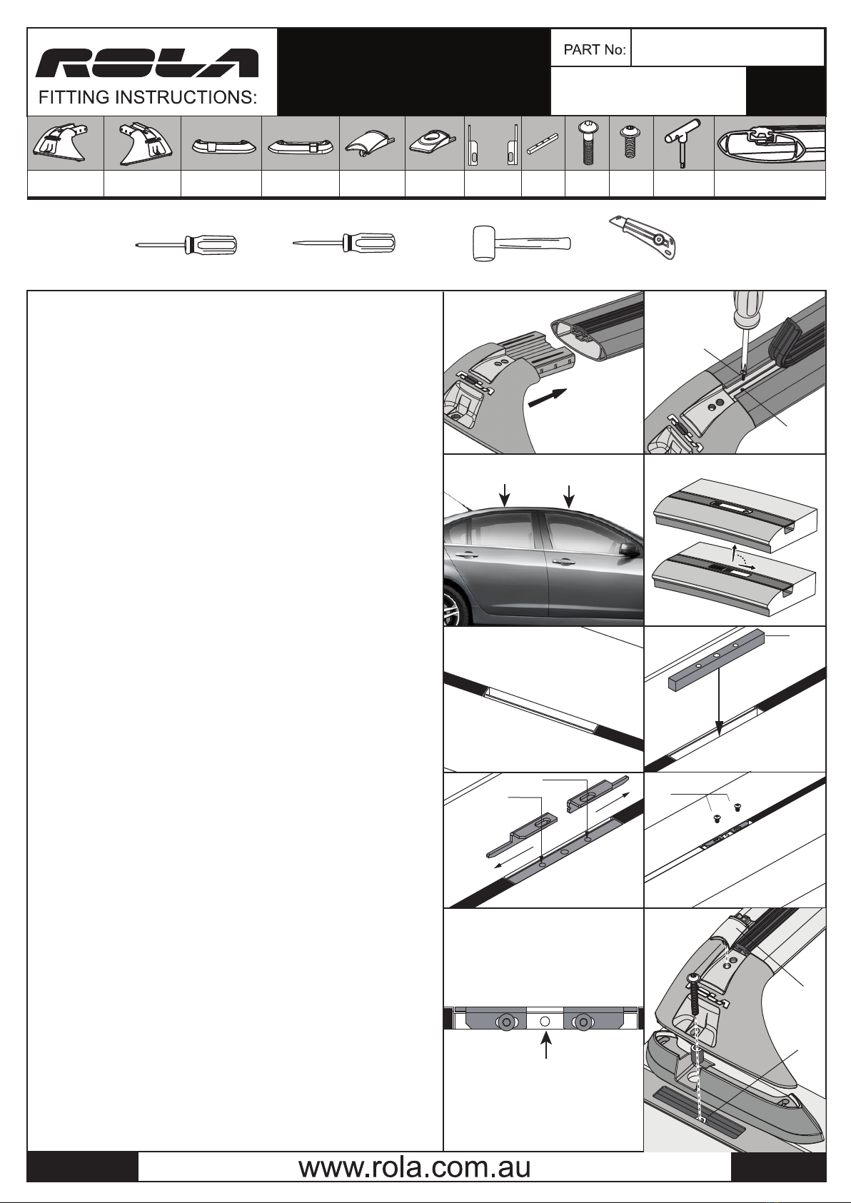
ASSEMBLY OF CROSS-BARS
1. Ensure the roof is clean, free from dust and grease.
2. Insert the neck of the End-Support into the void of the Cross-bar prole.
They are designed to be a tight t: use a rubber mallet if necessary (Fig.1)
3. Pull back the rubber Buer Strip about 20mm until the screw hole can be
accessed.(Fig. 2) Using a Phillips Head Screwdriver, fasten the screw through
the cross-bar and into the End Support.
Do this for all four sides and replace the buer strip.
NOTE: The longer cross-bars are to be tted to the front of the vehicle. Check
labelling on the underside of the cross-bar.
Screw hole
Screw
Fig. 1 Fig. 2
Fig. 3
Fig. 9
page 1 of 3
Figure. 6
M6x45
A
B
SLIDE
FULLY
REMOVE
ANCHOR POINT
COVER
or
(22-0837)
Fig. 7
(9018)
(9019)
Fig. 8
M5x10
M6 Anchor Point
YOUR ANCHOR POINT
ACCESS MAY LOOK DIFFERENT
TO THIS ILLUSTRATION
THREADED
ANCHOR HOLE
Quick Access
Snap-on Cover
M5x10
Fig. 4
Figure. 5
Figure 4a.
Fig. 10
ASSEMBLY OF CROSS-BARS
STEP 1: On the vehicle roof you will nd 4 Anchor Point Covers paired in two
locations indicated by the arrows in Fig 3.
Carefully remove these covers by sliding in the direction shown on the cover,
to reveal the anchor points as seen in Fig 4.
9019
9018
STEP 2
NOTE:
Take care when removing to avoid damaging Trim Cover Clip. Covers can
not be replaced while rack is tted.
For a Single-Bar tment, only remove the two Front or the two
Store the Anchor Point Covers and plugs safely while the Roof Racks are in use.
STEP 3
Revealing the anchor points you will notice a slot with folded ends closest to the
begining of the weather strip Fig 5. This tment will hook into these folded ends
and brace o a backing plate.
STEP 5
Place a Backing Plate (Part No. 22-0837) into the anchor point. This will self locate
into the bigger slot of the two as seen in Fig. 6
STEP 4
Now that the backing plate is seated into the anchor point. Place straps 9018 and
9019 directly on top of the backing plate. Then slide them into the outward
direction as seen Fig 7. The elongated end of the strap will slide into the smaller
slot and will be concealed by the folded end of the anchor point.
Secure straps 9018 and 9018 onto the backing plate using the M5x10 black xylan
bolts supplied Fig. 8. This kit comes wth the appropriated allen key to do so. After
completing this your anchor point should should appear as seen in Fig. 9
STEP 6
You are now ready to mount your cross bar assembly to the vehicle. Place the
front crossbar (usually the longer of the two or has label saying “FRONT” on the
underside of the roof bar) over the anchor points. Aligning the holes of the end
support and anchor point secure the bars to the roof using the M6 x 50 security
bolt provided. Use the the rubber sleeve provided to conceal the bolt. as per Fig.
10.
Repeat for the remaining anchor points and rear cross bar. You are now ready to
mount your “Accessories” set on to the cross-bars using the Global Mount
Channel. Once installed , insert the ‘Global Channel’ covers into the end supports.


