manuals.online logo
Brands
  1. Home
  2. •
  3. Brands
  4. •
  5. rollease acmeda
  6. •
  7. Engine
  8. •
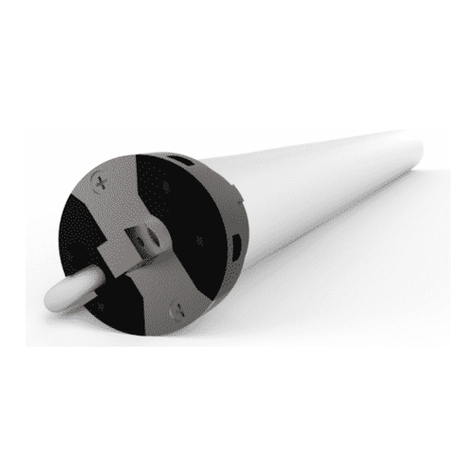
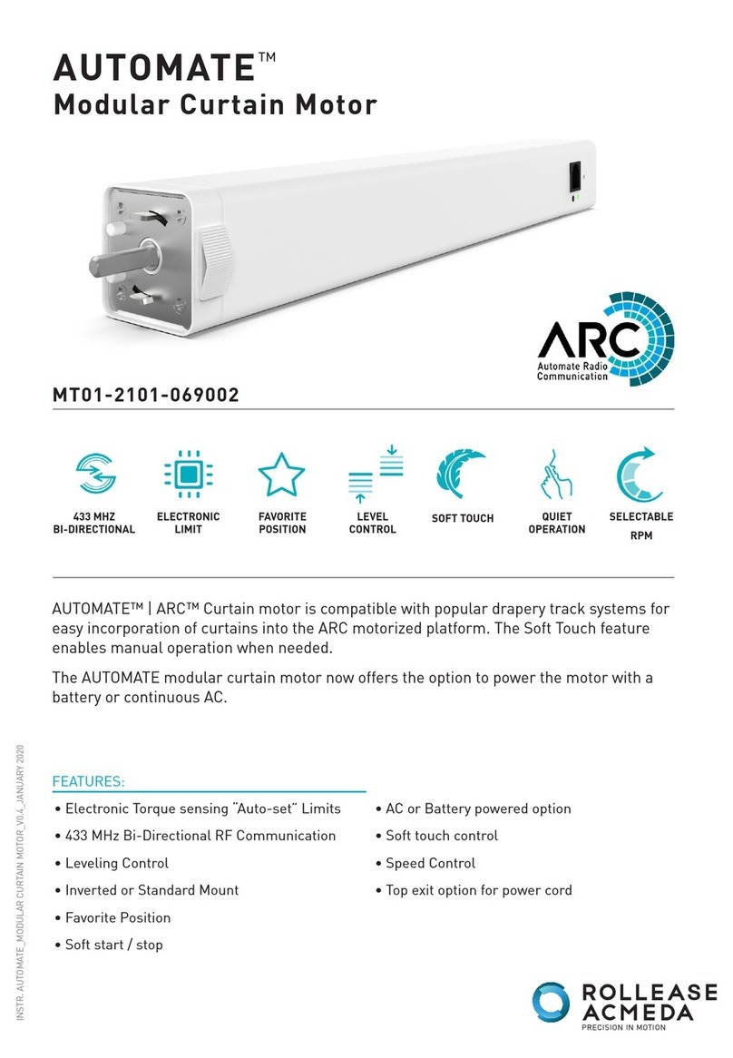
  9. rollease acmeda AUTOMATE MT01-2101-069002 User manual

rollease acmeda AUTOMATE MT01-2101-069002 User manual

1, This appliance can be used by children aged from 8 years and above and persons
with reduced physical, sensory or mental capabilities or lack of experience and
knowledge if they have been given supervision or instruction concerning use of
the appliance in a safe way and understand the hazards involved.
2, Children shall not play with the appliance.
3, Cleaning and user maintenance shall not be made by children without supervision.
4, If the supply cord is damaged, it must be replaced by the manufacturer, its service
agent or similarly qualified persons in order to avoid a hazard.
5, WARNING: the drive shall be disconnected from its power source during cleaning,
maintenance and when replacing parts.
6, LpA ≤ 70 dB(A).
7, The mass and the dimension of the driven part shall be compatible with the rated
torque and rated operating time.
8, The type of driven part the drive is intended for.
9, WARNING: Important safety instructions. It is important for the safety of persons
to follow these instructions. Save these instructions.
10, Do not allow children to play with fixed controls. Keep remote controls away
from children.
11, Frequently examine the installation for imbalance and signs of wear or damage
to cables and springs. Do not use if repair or adjustment is necessary.
12, Watch the moving shutter and keep people away until he shutter is completely
closed.
13, WARNING: Important safety instructions. Follow all instructions, since incorrect
installation can lead to severe injury.
14, Before installing the drive, remove any unnecessary cords and disable any
equipment not needed for powered operation.
SAFETY NOTE FCC Warning:
This equipment has been tested and found to comply with the limits for a Class B digital
device, pursuant to part 15 of the FCC Rules. These limits are designed to provide
reasonable protection against harmful interference in a residential installation. This
equipment generates, uses and can radiate radio frequency energy and, if not installed
and used in accordance with the instructions, may cause harmful interference to radio
communications. However, there is no guarantee that interference will not occur in a
particular installation. If this equipment does cause harmful interference to radio or
television reception, which can be determined by turning the equipment off and on, the
user is encouraged to try to correct the interference by one or more of the following
measures:
—Reorient or relocate the receiving antenna.
—Increase the separation between the equipment and receiver.
—Connect the equipment into an outlet on a circuit different from that to which the
receiver is connected.
—Consult the dealer or an experienced radio/TV technician for help.
MODIFICATION: Any changes or modifications not expressly approved by the grantee of
this device could void the user’s authority to operate the device.
IC :
-English:
This device complies with Industry Canada RSS standard(s). Operation is subject to the
following two conditions: (1) this device may not cause interference, and (2) this device
must accept any interference,including interference that may cause undesired operation
of the device.
2. Changes or modifications not expressly approved by the party responsible for
compliance could void the user's authority to operate the equipment.
-French:
Leprésent appareil est conforme aux CNR d'Industrie Canada applicable aux appareils radio
Exempts de licence. L'exploitation est autorisée aux deux conditions suivantes :
(1) l'appareil ne doit pas produire de brouillage, et (2) l'utilisateur de l'appareil doit
accepter tout brouillage radioélectrique subi, meme si le brouillage est susceptible d'en
compromettre le fonctionnement."
8, The type of driven part the drive is intended for.
9 , WARNING: Important safety instructions. It is important
for the safety of persons to follow these instructions.
Save these instructions.
10, Do not allow children to play with fixed controls. Keep
remote controls away from children
11, Frequently examine the installation for imbalance and
signs of wear or damage to cables and springs. Do not
use if repair or adjustment is necessary
12, Watch the moving shutter and keep people away until
he shutter is completely closed
13, WARNING: Important safety instructions. Follow all
instructions, since incorrect installation can lead to
severe injury.
14, Before installing the drive, remove any unnecessary
cords and disable any equipment not needed for
powered operation
Motor external battery
Motor external battery interface
The charging interface
Product introduction
External switch interface
LED light Setting button
Motor forward line
Motor reverse line
Public line
1. Not operating under low voltage motors:
Motor stop running when the supply voltage is lower than 13.5V, LED light will flash 5 times, buzzer
beep 5 times,prompt low voltage to be charged
2. Operating:
①The valid interval of the emitter button is 10s,the emitter will quit the set after 10s;
②The LED flashes or beep for hint,please do the next step after the hint.
3. Set limit position:
①Every time you install the motor,first set after a curtain opened travel to work properly;
②After setting,with power and memory function,after each power cycle required to
open or close a recovery stroke;
③After replacing the track or cord to be removed for the trip,and then set itinerary.
4. When the motor running without any operation,the maximum running time is 4
minutes,it will stop automatically.
5. One motor maximum can store 10 channels,over 10 channels,if still need add new channels,
it will be repeating covered in turn from second channel.
6. If the emitter lost,please set up again with new emitter.
Functional features:
Stall Protection
Built-in Receiver
Manual Override
Switch Control
Program Button
Solar Charging
Electronic Limit
Switch Direction
Auto Limit Setting
Run/Stop by Pulling Fabric
Preferred Stop Position
Lithium Battery with Quick Plug
-5
55
Working
Temperature
Parameter (More models and parameters are subject to the nameplate)
Motor installation
The assembly of rubber belt for curtain motor
The comfirmation of
profiled material dimension
7cm
The cap length
Leave half teeth
The length of profiled material = The total
lenth of track - The cap length × 2
The total length of track is 2m
The length of profiled material: 200cm-14cm=186cm
Use the screw driver to
place the parts like the
gear into the lower cover
Refer the complete lower
cove in below picture
Thread the rubber belt
into thethe lower cover
Fix the cut rubber belt end
with the belt fasten button
Keep this end complete
Install the clip part like the referance picture
and insert the track into the lower cover
Slide the slip part to the other end to be flush with the
head rail.Cut the other end of rubber belt with 11.5cm left
The joint assembly of track
Btrack
Track joint board
Track joint
bracket
The f0llowing steps pls refer to
“the assembly of rubber belt and track”
Insert the track joint bracket
for one end to the track joint
Fix the screws
Note: The track needs to be engrafted when
the length is less the required
The track needs to be engrafted when
inconvenient to transport
11.5cm
Insert the track
joint board into
the two ends of track
The marked position is in the
middle of the slip parts.Half of
the slip parts are in the head
rail as in the picture
Seperate the lower cover and the headrail with the
11.5cm belt remaining outside the headrail.Then fix
two fasten buttons on the same side of rubber belt
(it is to figure out the position of the other slip part.)
Leave one teeth
between these two
belt fasten button
Install the belt fasten button and
the slip part as in the picture
Install the belt facton button
and the slip part as in the picture
After one slip part installed,then thread the other
end of the belt through the other lower cover
These two slip parts is successfully installed
4
Folding method for joint track (for easy transit)
The installation method for curtain motor
5
4
3
5
4
3
Assemble the curtain motor
track at appropriate place,
then fix with screws
Check the position of
brackets,fix it at an
appropiate place on the track
Please check assembling is ok
Assemble the motor Finish assembling
The runner are installed
The hook
Place the hook and the upper cover into the track
Search for the sl-
ip part connected
with the ends of
the rubber belt
Take off the screw
of the slip parts
and the connection
bracket
Track folding method
The overlap arm
which is connected
to the two ends of
rubber belt
Pull the slip parts
slightly and seper-
ate the connection
part at the same
time
Push the connec-
tion parts to one
side
Fold the track
Unfold the
folded track
Combine the
track slowly
Push the con-
nection bracket
to the connec-
tion part
Restoring the track
Screw the co-
nnnection bra-
cket and install
the slip parts
The track is
successfully
assembled
The slip
parts
Slide the runners into the track
Operation note
Please read the following precautions before use:

READING
MT01-2101-069002
Type
1.2N.m
Rated Torque
(N.m)
80-120RPM
Rated speed
(RPM)
DC 15V
Rated Voltage
(V)
433.925MHz
Emission
Frequency(MHz)
Curtain Motor-
MT01-2101-069002
Specification
(A-01)
OPERATION GUIDE
Fault and solution
Note: Press the open button, if the curtain closed, please perform the reverse of direction setting;Only one emitter can
be saved without the limit.
Note: the method one needs to be carried out without a trip; When the change is successful, it will delete the settings
related to the limit and need to reset the limit.
Note: If the motor is short sound twice, it means the speed is already fast or slow; when there is no limit, the motor
defaults to low speed running. When there is limit, the motor will run fast by default.
Setting up is ok
LED flashes x5
“Di” x3
LED flashes x1
T<10s
2 Switch direction
3 Speed regulation
Long press 2s
Successful change the direction
LED flashes x5
“Di” x3
LED flashes x3
Long press 10s Loosen button Press 1s
Successful change the direction
LED flashes x5
“Di” x3
Method one
Method two

1, Acceleration setting
LED flashes x1
“Di” x1
LED flashes x5
“Di~” x1
LED flashes x1
“Di” x1
LED flashes x1
“Di” x1
LED flashes x5
“Di~” x1
LED flashes x1
“Di” x1
Motor speed increases
Press 1s
3
Press 1s Press 1s
Press 1s Press 1s Press 1s
2, Deceleration setting
Motor speed is reduced
3
“Di” x1
“Di” x3
4 Limit position setting
Limit is ok
LED flashes x5
“Di” x3
1, Set the limit
LED flashes x1
“Di” x1
LED flashes x5
“Di” x3
LED flashes x1
“Di” x1
LED flashes x1
“Di” x1
LED flashes x5
“Di” x3
LED flashes x1
“Di” x1
Note: After the limit is set, the motor enters the user mode; after the limit is deleted, the motor enters the factory mode.
2, Cancel the limit
Cancel the limit is ok
3 3
3
User mode
1 Preferred stop position
Preferred
stop posi-
tion is ok
Run to the re-
quired preferr-
ed stop position
After the up limit and down limit setting, you can set preferred stop position between them as the half open position
1, Set preferred stop position
3, Cancel preferred stop position
The motor moves to preferred stop position automatically
Long
press 2s
2, Run to preferred stop position
3
Cancel preferred stop position is ok
Slow flash x1
“Di~” x1
1, Fine-tuning open limit position
2, Fine-tuning close limit position
2 Fine-tuning open/close limit position
Slow flash x1
“Di~” x1
Long
press 5s
LED flashes x5
“Di” x3
Slow flash x1
“Di~” x1
LED flashes x5
“Di” x3
Open limit
fine-tuning
success
Note: after entering fine-tuning limit mode, if not confirm new schedule points within 2 minutes, or press P1 button
or emitter setting button automatically quit this pattern, limit position remains unchanged.
Enter the
fine-tuning
limit mode

Long press 2s
Long
press 5s
Long press 2s

Close limit
fine-tuning
success
Enter the
fine-tuning
limit mode
 
Press open/close button or
hand pull the curtain adjust
the new close limit position
or
3 Add/delete emitter
3 3 3
Add emitter is ok
4 Weak electric switch mode selection
3
LED flashes x1
“Di” x1
Set up is ok
1, Double-button reboundable switch mode(The factory default weak electric switch mode)
LED flashes x3
LED flashes x5
“Di” x3“Di”x3
3, Single-button cyclic switch mode
3
2, DC246 switch mode
3
Set up is ok
Set up is ok
5 Run/stop by pulling fabric
Note: repeat this operation can run by pulling fabric;The default is run by pulling fabric.
Stop by pulling fabric
LED flashes x5
“Di” x3
6 The search function
Note: this operation needs to be done without the motor to the code or the motor to the search emitter;Emitter after
entering search pattern, if received equipment emitter LED lights flashing, motor run continuously for 2 minutes, not
received the emitter exit search instructions, the motor will exit the search pattern.
The emitter
enters the
search mode
Search to match motor, motor cycle
point moving operation
LED cycle
flashing
Press 1s
3
+
7 Reset to factory mode
Reset to factory mode successfully
LED flashes x8
“Di” x4
Button specification
1 Setting up
Factory mode
Long press 2sLoosen buttonLong press 2s
The curtain was opened and
the obstruction stopped
The curtains were
closed and stopped
Press 1sPress 1s
Press 1s Press 1s Press 1s
LED flashes x1
“Di” x1
LED flashes x5
“Di” x3
LED flashes x1
“Di” x1
Press 1s Press 1s Press 1s
LED flashes x1
“Di” x1
LED flashes x1
“Di” x1
Press 1s Press 1s Press 1s
Press 1s Press 1sPress 1s
Press x1Long
press 10s
Long press 2sLoosen button
or
Press open/close button or
hand pull the curtain adjust
the new open limit position
Note: Emitter is the one already matched code, while emitter has not;Repeat this to remove the newly added emitter.
Press x2Long
press 10s
Long press 2sLoosen button
Press x3Long
press 10s
Long press 2sLoosen button
Press x1Long
press 10s
Loosen button
Long
press 14s
Loosen button
LED flashes x2
“Di” x2LED flashes x3
LED flashes x5
“Di” x3“Di”x3
LED flashes x3
“Di” x3LED flashes x3
LED flashes x5
“Di” x3“Di”x3
LED flashes x3 “Di”x3
COMMON FAULTS PROCESSING METHODNUMBER
1The motor is
not running Check the power supply
2Unable to control
remote controller 1, Check the emitter for the code;2, Replace the emitter battery
3Remote control
on the contrary Implement the reverse of direction setting
5External switch
on the contrary Replacement switches line order
4External switch
is out of control Check the external switch motor cable is intact
6Cannot close 1, Check emitter's open button to ensure if it works with open function,
if not,please change direction firstly;2, check limit position;
7Always hit or couldn
not get to the edge Cancel the limit,setting again
8With the hand to
pull,feeling stuck Set the limit of the trip
9Encounter obstacles
will not stop Check the screw used to fixed orbital
MT01-2101-069002
Specification
(A-01)
P
2
M
P
2
Lithiu
m
Cell
3
V
P
2
Up button
Stop button
Down button
Setting button

Other manuals for AUTOMATE MT01-2101-069002

1

Other rollease acmeda Engine manuals

rollease acmeda AUTOMATE ARC User manual

rollease acmeda

rollease acmeda AUTOMATE ARC User manual

rollease acmeda AUTOMATE User manual

rollease acmeda

rollease acmeda AUTOMATE User manual

rollease acmeda AUTOMATE Installation manual

rollease acmeda

rollease acmeda AUTOMATE Installation manual

rollease acmeda AUTOMATE Installation manual

rollease acmeda

rollease acmeda AUTOMATE Installation manual

rollease acmeda AUTOMATE MT01-4001-002 Series User manual

rollease acmeda

rollease acmeda AUTOMATE MT01-4001-002 Series User manual

rollease acmeda AUTOMATE AU User manual

rollease acmeda

rollease acmeda AUTOMATE AU User manual

rollease acmeda AUTOMATE AX30 User manual

rollease acmeda

rollease acmeda AUTOMATE AX30 User manual

rollease acmeda AUTOMATE MT01-2101-069002 User manual

rollease acmeda

rollease acmeda AUTOMATE MT01-2101-069002 User manual

rollease acmeda AUTOMATE MT01-1145-069011 Installation manual

rollease acmeda

rollease acmeda AUTOMATE MT01-1145-069011 Installation manual

Popular Engine manuals by other brands

Doosan D35S-5 Service manual

Doosan

Doosan D35S-5 Service manual

Yanmar 3JH5E Operation manual

Yanmar

Yanmar 3JH5E Operation manual

GAPOSA XQ50 instructions

GAPOSA

GAPOSA XQ50 instructions

King Canada KCG-65 instruction manual

King Canada

King Canada KCG-65 instruction manual

Mercury MerCruiser D7.3L D-Tronic LD installation manual

Mercury

Mercury MerCruiser D7.3L D-Tronic LD installation manual

Briggs & Stratton Fource 21100 Operating and maintenance instructions

Briggs & Stratton

Briggs & Stratton Fource 21100 Operating and maintenance instructions

SCHUNK ERS 135 048V Assembly and operating manual

SCHUNK

SCHUNK ERS 135 048V Assembly and operating manual

Nakanishi EMS-3060K Operation manual

Nakanishi

Nakanishi EMS-3060K Operation manual

Briggs & Stratton 195700 Series Operator owner's manual

Briggs & Stratton

Briggs & Stratton 195700 Series Operator owner's manual

MINN KOTA Riptide 80 ST quick start guide

MINN KOTA

MINN KOTA Riptide 80 ST quick start guide

Kohler Command Pro CS Series owner's manual

Kohler

Kohler Command Pro CS Series owner's manual

ACM TITANSIDE installation manual

ACM

ACM TITANSIDE installation manual

Kohler Command PRO CH270 owner's manual

Kohler

Kohler Command PRO CH270 owner's manual

Craftsman 143.991004 Operator's manual

Craftsman

Craftsman 143.991004 Operator's manual

Briggs & Stratton Vanguard 290000 Operating & maintenance instructions

Briggs & Stratton

Briggs & Stratton Vanguard 290000 Operating & maintenance instructions

Meyer ELECTRAK 1 manual

Meyer

Meyer ELECTRAK 1 manual

Marine Power Solutions MP-446 Operation manual

Marine Power Solutions

Marine Power Solutions MP-446 Operation manual

Daewoo P158LE Operation & maintenance manual

Daewoo

Daewoo P158LE Operation & maintenance manual

manuals.online logo
manuals.online logoBrands
  • About & Mission
  • Contact us
  • Privacy Policy
  • Terms and Conditions

Copyright 2025 Manuals.Online. All Rights Reserved.