Page 3of 8 Copyright ROMPA® Ltd
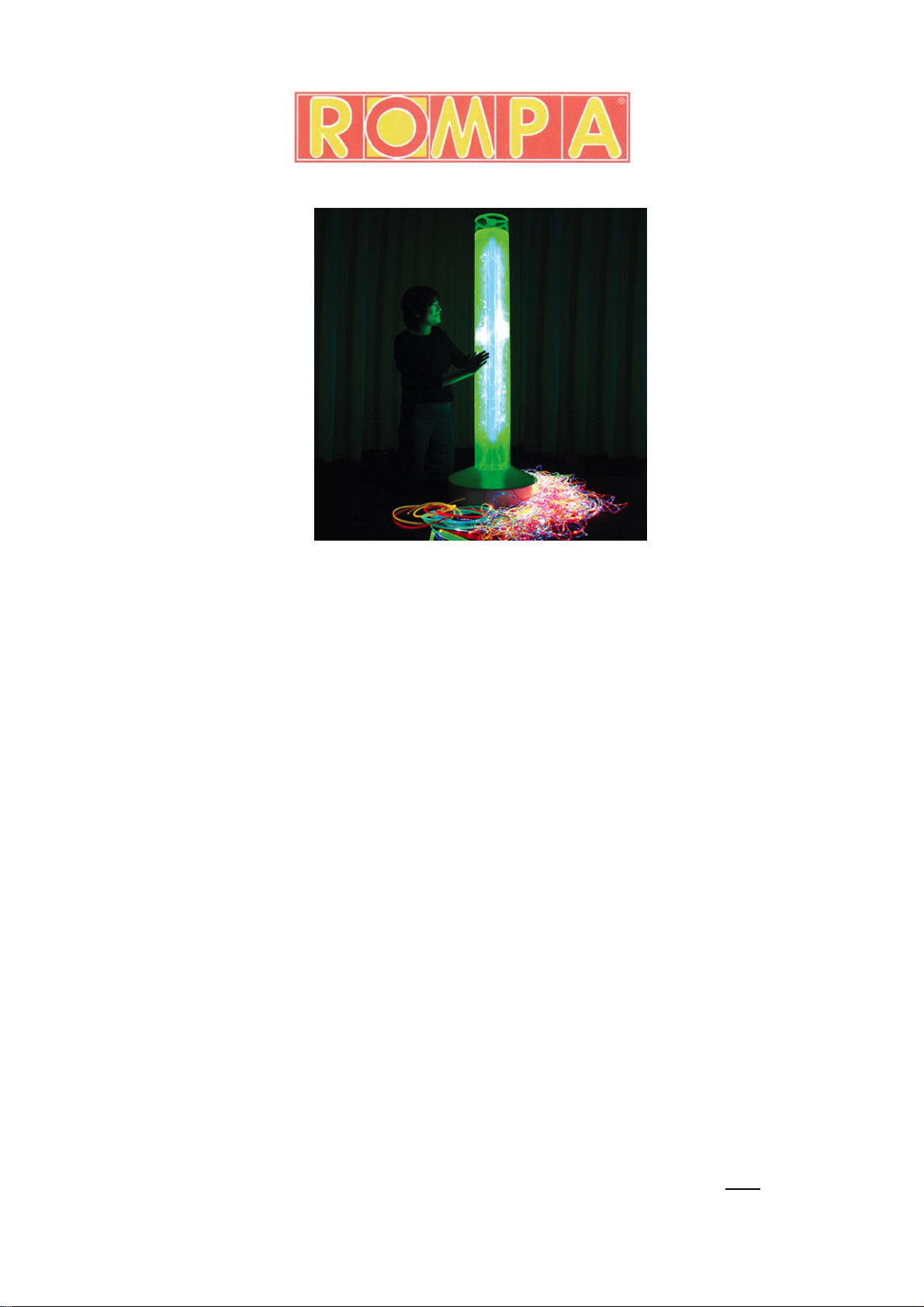
FLUORESCENT BUBBLE TUBE 17911, KH 11.10
CARE AND MAINTENANCE
TO EMPTY THE BUBBLE TUBE
1. Use an appropriate pump. Remove the cap (round lid at the top of the tube) and remove the
water from the top of the tube using your pump. A pump is available separately from
ROMPA®: code 20601. From November 2011, ROMPA®Bubble Tubes no longer have a
drain hose at their base.
2. Refill the Bubble Tube as required.
TO CHANGE UV TUBE
1. Switch of the bubble tube. Take off the bubble tube cap – the tube must be changed from the
bottom of the column but the cap must be removed so that the white base can be removed.
2. The bubble tube must be emptied following the instructions above. Do not replace the base
cover yet.
3. Separate the bubble tube column from the base by removing the four screws. Carefully
release the black wires from inside the column (without detaching them completely) so that
the column can be placed on its side. This is so that once it is released, the fluorescent tube
will not drop suddenly to the floor.
4. Remove the three screws from the centre of the column. Put these screws in a safe place.
5. Once the screws are removed, the central part of the column holding the fluorescent tube will
slide out. The fluorescent tube is held in place at each end by two pins. Gently pull the pins
out of their ends and replace the used tube. Replace with a new tube of the same
specification: 4ft UV Fluorescent Tube 36watt.*
6. Reconnect the pins.
7. Replace the UV tube in the column and then replace the three screws.
8. Tuck the black wire back inside the column.
9. Replace the column onto the base. Refill the tube.
10.Replace the base cover and cap.
* Replacement tubes are available from ROMPA®. Please contact us, quoting code 4047.
However, these UV tubes are widely available from hardware shops and DIY centres. Given the
fragile nature of these tubes, and the high probability that they cab become damaged during
transit, we recommend that you purchase replacement tubes from a hardware shop/DIY centre.
GENERAL CARE
Wash the exterior of the Maxi Bubble Tube with a slightly soapy cloth. Wipe excess soap away
with a damp cloth. NOTE: Never use solvent based cleaning products, methylated spirits,
alcohol wipes or liquid detergents to clean the Bubble Tube.
The environment the Fluorescent Bubble Tube is in will affect how often the water needs to be
changed. Bubble tubes in dark, damp environments with minimal ventilation will need changing
at a different frequency to those in bright, well-ventilated rooms. Plan for holidays. For example,
if the bubble tube will be switched off for long periods, empty the water out. You do not want to
return from a long holiday to find the water is green and unpleasant!
If necessary, for example if the tube is used in an area where lime-scale in water is a problem, it
may be advisable to use an appropriate water softener. Failure to cleanse your bubble tube
water and/or use an appropriate water softener can block the valves of the bubble tube and so
encourage product failure.
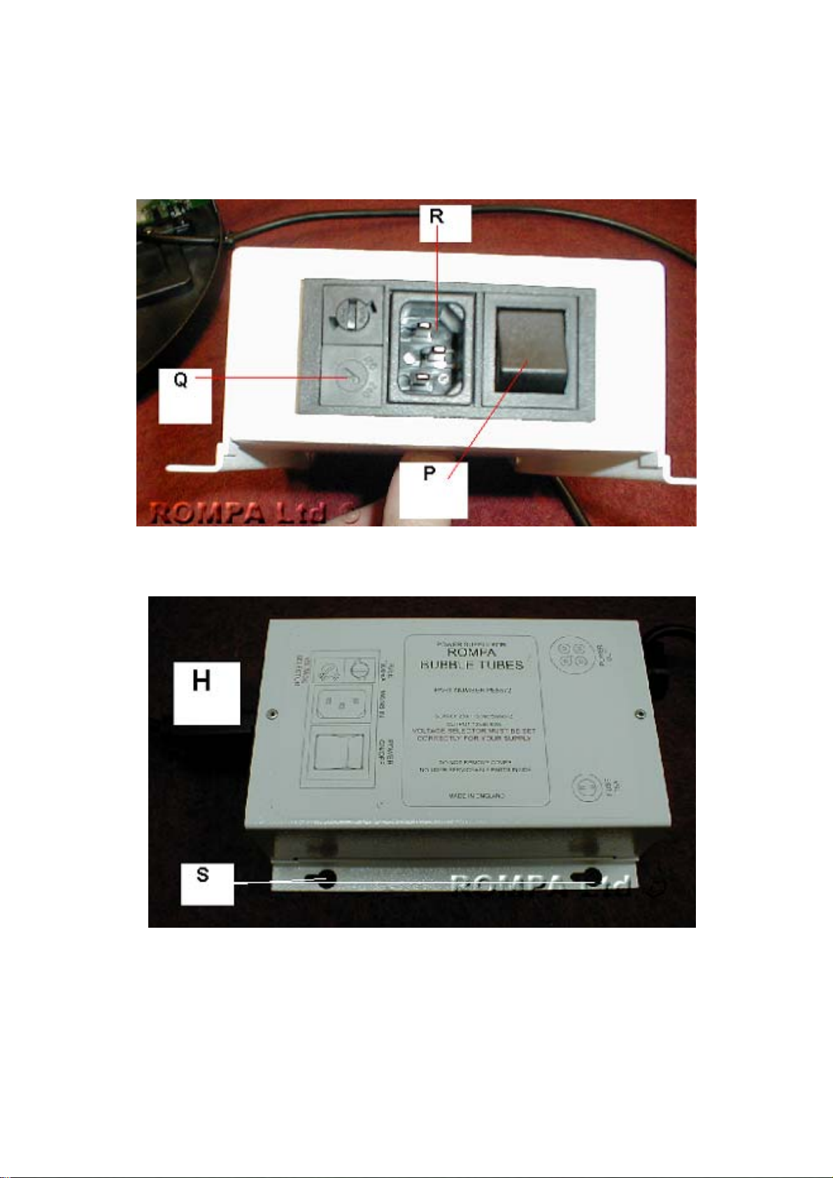
TECHNICAL INFORMATION
Bubble Tube:
2 x Pumps (L): 12 Volt 50/60 Hz, Schwarzer Prazision, type SP 203 S.
Power Supply Control Unit (H), 230 Volt (110V)
50/60Hz, Output: 12V DC, 60W