Rongpeng 820 User manual

AIRLESS SPRAY GUN
MODEL: 820
3600psi (24.8pa) Maximum working pressure
4 Finger type lightweight spray gun with 517
reversible spray tip and guard.
Instructions Manual
This manual contains important warnings
and information. Read and Keep for
reference.

Technical Data:
Maximum working pressure
3600Psi(24.8Mpa,248Bar)
Inlet fitting
1/4”-18-NPSM external thread
Operating temperature range
40°to 115°F(4℃to 46℃)
Weight
13.4oz(380g)
Important Safety Instructions:
•Do not spray flammable or combustible materials near an open flame, pilot lights or sources of ignition such as
hot objects, cigarettes, motors, electrical equipment and electrical appliances. Avoid creating sparks from
connecting and disconnecting power cords.
•For units intended for use with only water-based or mineral spirit-type materials with a minimum flash point of
38ºC (100ºF) —Do not spray or clean with liquids having a flash point of less than 38ºC (100ºF). Flash point is
the temperature at which a fluid can produce enough vapor to ignite.
•Use extreme caution when using materials with a flashpoint below 100ºF (38ºC). Refer to your pump manual
to determine if these materials can be sprayed.
•Paint or solvent flowing through the equipment is able to result in static electricity. Static electricity creates a
risk of fire or explosion in the presence of paint or solvent fumes. All parts of the spray system, including the
pump, hose assembly, spray gun and objects in and around the spray area shall be properly grounded to
protect against static discharge and sparks. Use only conductive or grounded high-pressure airless paint
sprayer hoses specified by the manufacturer.
•Verify that all containers and collection systems are grounded to prevent static discharge.
•Connect to a grounded outlet and use grounded extension cords (electric models only). Do not use a 3 to 2
adapter.
•Do not use a paint or solvent containing halogenated hydrocarbons. Such as chlorine, bleach mildewcide,
methylene chloride and trichloroethane. They are not compatible with aluminum. Contact the coating supplier
about compatibility of material with aluminum.
•Keep spray area well ventilated. Keep a good supply of fresh air moving through the area to keep the air within
the spray area free from accumulation of flammable vapors. Keep pump assembly in well ventilated area. Do
not spray pump assembly.
•Do not smoke in the spray area.
•Do not operate light switches, engines, or similar spark producing products in the spray area.
•Keep area clean and free of paint or solvent containers, rags, and other flammable materials.
•Know the contents of the paint and solvents being sprayed. Read all Material Safety Data Sheets (MSDS) and
container labels provided with the paints and solvents. Follow the paint and solvent manufacture’s safety
instructions.
•Place pump at least 25 feet (7.62 meters) from the spray object in a well ventilated area (add more hose if

necessary). Flammable vapors are often heavier than air. Floor area must be extremely well ventilated. The
pump contains arcing parts that emit sparks and can ignite vapors.
•Plastic can cause static sparks. Never hang plastic to enclose spray area. Do not use plastic drop cloths when
spraying flammable material.
•Fire extinguisher equipment shall be present and working.
•Do not aim the gun at, or spray any person or animal.
•Keep hands and other body parts away from the discharge. For example, do not try to stop leaks with any part
of the body.
•NEVER put your hand in front of the gun. Gloves will not provide protection against an injection injury.
•ALWAYS keep the tip guard in place while spraying. The tip guard provides some protection but is mainly a
warning device.
•Only use a nozzle tip specified by the manufacturer.
•Use caution when cleaning and changing nozzle tips. In the case where the nozzle tip clogs while spraying,
ALWAYS lock gun trigger, shut pump off, and release all pressure before servicing, cleaning tip or guard, or
changing tip. Pressure will not be released by turning off the motor. The PRIME/SPRAY valve or pressure bleed
valve must be turned to their appropriate positions to relieve system pressure. Refer to PRESSURE RELIEF
PROCEDURE described in the pump manual.
•Do not leave the unit energized or under pressure while unattended. When the unit is not in use, turn off the
unit and relieve the pressure in accordance with the manufacturer’s instructions.
•High-pressure spray is able to inject toxins into the body and cause serious bodily injury. In the event that
injection occurs, seek medical attention immediately.
•Check hoses and parts for signs of damage, a leak can inject material into the skin. Inspect hose before each
use. Replace any damaged hoses or parts. Only use TITAN original-high-pressure hoses in order to ensure
functionality, safety and durability.
•This system is capable of producing 3600psi / 248 Bar. Only use replacement parts or accessories that are
specified by the manufacturer and that are rated a minimum of 3600 PSI. This includes spray tips, nozzle
guards, guns, extensions, fittings, and hose.
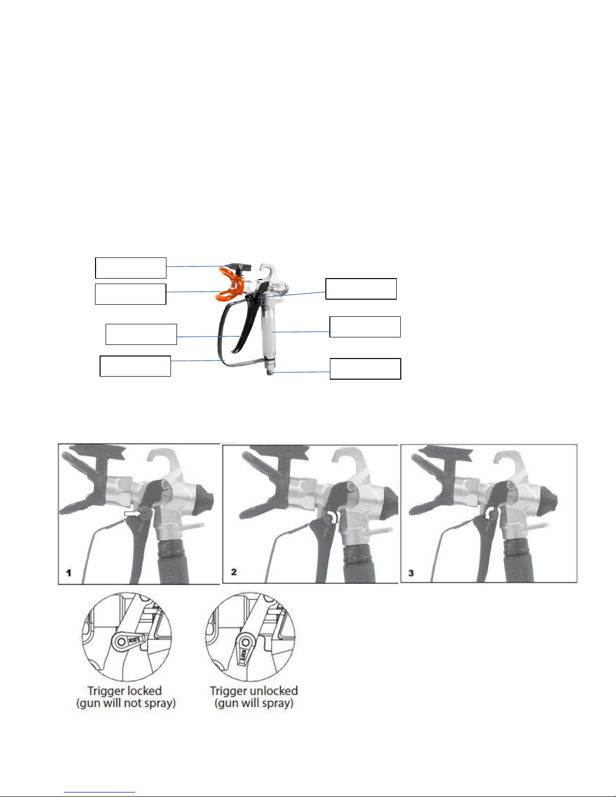
•Always engage the trigger lock when not spraying. Verify the trigger lock is functioning properly.
•Verify that all connections are secure before operating the unit.
•Know how to stop the unit and bleed pressure quickly. Be thoroughly familiar with the controls. Pressure will
not be released by turning off the motor. The PRIME/SPRAY valve or pressure bleed valve must be turned to
their appropriate positions to relieve system pressure. Refer to PRESSURE RELIEF PROCEDURE described
in the pump manual.
•Always remove the spray tip before flushing or cleaning the system.
•Always wear appropriate gloves, eye protection, clothing and a respirator or mask when painting.
•Do not operate or spray near children. Keep children away from equipment at all times.

•Do not overreach or stand on an unstable support. Keep effective footing and balance at all times.
•Stay alert and watch what you are doing.
•Do not operate the unit when fatigued or under the influence of drugs or alcohol.
•Do not kink or over-bend the hose. Airless hose can develop leaks from wear, kinking and abuse. A leak can
inject material into the skin.
•Do not expose the hose to temperatures or pressures in excess of those specified by manufacturer.
•Do not use the hose as a strength member to pull or lift the equipment.
•Use lowest possible pressure to flush equipment.
•Follow all appropriate local, state and national codes governing ventilation, fire prevention and operation.
•Before each use, check all hoses for cuts, leaks, abrasion or bulging of cover. Check for damage or movement
of couplings. Immediately replace hose if any of those conditions exist. Never repair a paint hose. Replace with
a conductive high-pressure hose.
•Do not spray outdoors on windy days.
•Always unplug cord from outlet before working on equipment (electric models only).
Instructions For Operation
Using the Gun Trigger Lock
Always engage the gun’s trigger lock when the gun is not in use(1).
1. To lock the trigger, rotate the trigger lock backward until it stops(2).
2. To unlock the trigger, rotate the trigger lock forward until it is vertical(3).
Tip
Tip guard
Trigger
Trigger guard Material inlet
Handle
Trigger lock

SetupNever attempt to assemble, change, or clean the gun, tip, or tip guard without first relieving
pressure from the spray system. Follow the “Pressure Relief Procedure” in the sprayer’s Manual.
Always use a tip safety guard for added protection against injection. Beware that the guard alone
will not prevent injection. Never cut off tip guard! Always engage gun trigger lock when the gun is
not in use. Before servicing equipment, consult Owner’s Manuals and follow all warnings.
1. Set up the sprayer. Refer to the instructions in the sprayer’s Manual.
2. Attach a grounded, airless spray hose to the material inlet on the gun. Using two wrenches (one on the gun
and one on the hose), tighten securely(4).
3. With the tip and tip guard off the gun, start the sprayer. Flush and prepare the spray system according to the
sprayer’s Owner’s Manual. Inspect the spray system to make sure that all fittings are secure and that there are
no leaks.
4. Perform the “Pressure Relief Procedure” described in the sprayer’s Owner’s Manual.
5. Using the arrow head on the tip handle, insert the tip seal and tip seal retainer into the back of the tip guard(5).
Press in for final adjustment.
6. Insert the tip into the slot on the tip guard(6).
7. Thread the tip guard onto the gun. Position the tip guard in the desired spraying position and tighten securely.
NOTE: The arrow on the tip handle should be pointing in the forward direction for spraying.
Operation
1. Make sure the arrow on the tip handle is pointing in the forward direction for spraying.
2. Start the sprayer. Refer to the instructions in the sprayer’s Manual.
3. Adjust the fluid pressure on the sprayer until the spray is completely atomized. Always spray at the lowest
pressure necessary to get the desired results.
NOTE: The spray tip determines the size of spray pattern and coverage. When more coverage is needed,
use a larger tip instead of increasing fluid pressure.
4. To clear a clogged tip:

a. Rotate the tip 180ºso that the arrow on the tip handle is pointing opposite the spray direction.(7)
b. Trigger the gun once so that the pressure can blow the clog out.
Important: Never pull the trigger more than once at a time with the tip
in the reverse position.
c. Continue this procedure until the tip is clear of the clog.
Changing a Tip
Tips can be removed and replaced easily without disassembling the gun.
Never attempt to change or clean the tip or tip guard without
first performing the “Pressure Relief Procedure.”
1. Perform the “Pressure Relief Procedure” described in the sprayer’s
Manual.
2. Remove the tip from the slot on the tip guard.
3. Insert the new tip into the slot on the tip guard. The arrow on the tip handle
should be pointing in the forward direction.
Removing the Seal and Tip Seal
1. Remove the tip and tip guard from the spray gun.
2. Remove the seal and tip seal from the back of the tip guard(8).
Identifying Tip Sizes
To identify tip sizes, use the following formula. A “517” tip size will be used in this example.
The first digit multiplied by two represents the size of the spray pattern when spraying 12”(30cm) away from the
work surface: 5 x 2 = 10” spray pattern
The second two digits represent the diameter of the orifice on the tip: 17 = .017”(0.43mm) orifice
NOTE:
Worn spray tips will adversely affect the spray pattern and result in reduced production, poor finish,
and wasted material. Replace worn tips immediately.
Cleanup
Maintaining a clean gun is important to ensure trouble-free operation. Flush the gun after each use and store in
a dry location. Do not leave the gun or any of its parts in water or solvents.
Special cleanup instructions for use with flammable solvents:
•Always flush spray gun preferably outside and at least one hose length from spray pump.
•If collecting flushed solvents in a one gallon metal container, place it into an empty five gallon container, then
flush solvents.
•Area must be free of flammable vapors.
•Follow all cleanup instructions.
Important: The sprayer, hose, and gun should be cleaned thoroughly after daily
use. Failure to do so permits material to cake, seriously affecting the performance
of the unit.
Always spray at minimum pressure with the tip and tip guard removed when
using mineral spirits or any other solvent to clean the sprayer, hose, or gun.
Static electricity buildup may result in a fire or explosion in the presence of
flammable vapors. Hold the gun firmly against a metal container while flushing.
Maintenance
Follow all safety precautions as described in the Safety
Precautions section of this manual before proceeding.
NOTE: Refer to the Parts List section in this manual for part identification.
Replacing/Servicing the Seal Assembly

If your spray gun leaks or spits at the tip when you release the trigger, the needle or seat is worn, damaged, or
dirty and must be replaced or cleaned.
Never attempt to perform maintenance on the spray gun
without first performing the “Pressure Relief Procedure.”
1. Perform the “Pressure Relief Procedure” and disconnect the fluid hose from the gun.
2. Remove the end cap and the packing spring from the rear of the gun head.
3. Using a 3/8” socket, remove the packing seal assembly from the rear of the gun head.
4. Soak the removed parts in the appropriate solvent and wipe clean.
5. Inspect the parts for wear or damage and use new parts during reassembly of the gun, when necessary.
NOTE: Lubricate all packings and moving parts before reassembly with a lithium-based grease.
6. Make sure the two retractor pins inside the gun head are still in the correct position.
7. Insert the packing seal assembly into the rear of the gun head and thread it by hand until it stops.
8. Using a 3/8” socket, tighten the packing seal assembly. Torque to 5 Nm (3.7 ft./lbs.).
9. Grease both ends of the packing spring and place it over the packing seal assembly in the gun head.
10. Place the end cap over the packing spring so that the pilot inside the end cap seats inside the packing
spring.
11. Push the end cap toward the gun head while threading it into the gun head. Using a wrench, tighten the end
cap securely.
12. Perform the “Adjusting the Packing Seal Assembly” procedure described below.
Adjusting the Packing Seal Assembly
Proper adjustment of the seal assembly is essential to ensure positive shut-off when the trigger is
released.
1. Insert an 1/8” hex wrench through the hole in the center of the end cap until it seats inside the
packing seal adjustment screw.
2. Turn the packing seal adjustment screw clockwise until the ball on the packing seal assembly can be felt
seating into position. Then, turn the screw 1/4 turn more for proper tension.
Replacing/Removing the Filter
1. Pull the bottom of the trigger guard forward so that it comes loose from
the handle assembly(9).
2. Loosen and remove the handle assembly from the gun head(10).
3. Pull the old filter out of the gun head(11).
4. Slide the new filter, tapered end first, into the gun head(12).
5. Make sure all the parts are clean and the handle seal is in position inside
the gun head.
6. Thread the handle assembly into the gun head until secure.
7. Snap the trigger guard back onto the handle assembly.

Explosive View and Parts list
Issue date:
Version no.:
No. Figure number Description Qty.No. Figure number Description Qty.
Material inlet connection
Washer
Material inlet joint
Interval washer
Material connection core
O-ring 6*2
Handle
Washer
Locked nut M5
Switch seat
Switch pin
Gun body
Hex bolt M4*30
Nut M4
Trigger pole joint
Spring
Trigger pole
Trigger
Tigger guard
Thimble
Copper washer
Thimble sealing washer
Spring core
Thimble spring
Thimble head washer
Thimble head assembly
Washer
Plug insert
Plug seat
Rubber plug
Nozzle cap
Reversible Tip assembly
Nut
Tip seat
Tip Guard
Note: If you need spare parts of this model, pls feel free to contact us or the distributor where you bought this tool. Tks!
Table of contents
Other Rongpeng Paint Sprayer manuals