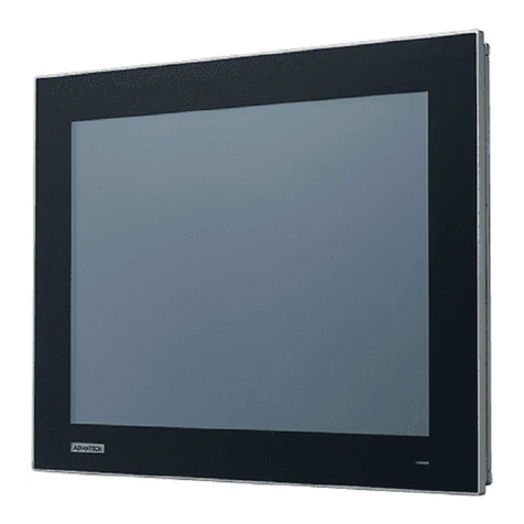
Rose electronics RackView RVR-LCDA17/DVI User manual

RackView
LCD Panel
Rack Mount
LCD Display Panel
Installation
and
Operation Manual
10707 Stancliff Road
Houston, Texas 77099
Phone: (281) 933-7673

LIMITED WARRANTY
Copyright Rose Electronics 2018. All rights reserved.
No part of this manual may be reproduced, stored in a retrieval system, or transcribed in any form or any means, electronic or mechanical, including photocopying and
recording, without the prior written permission of Rose Electronics.
manual-rackview-lcd-panel-2018-03-23
Rose Electronics®warrants the RackView LCD Display Panel to be in good working order for one year from
the date of purchase from Rose Electronics or an authorized dealer. Should this product fail to be in good
working order at any time during this one-year warranty period, Rose Electronics will, at its option, repair or
replace the Unit as set forth below. Repair parts and replacement units will be either reconditioned or new. All
replaced parts become the property of Rose Electronics. This limited warranty does not include service to
repair damage to the Unit resulting from accident, disaster, abuse, or unauthorized modification of the Unit,
including static discharge and power surges.
Limited Warranty service may be obtained by delivering this unit during the one-year warranty period to Rose
Electronics or an authorized repair center providing a proof of purchase date. If this Unit is delivered by mail,
you agree to insure the Unit or assume the risk of loss or damage in transit, to prepay shipping charges to the
warranty service location, and to use the original shipping container or its equivalent. You must call for a return
authorization number first. Under no circumstances will a unit be accepted without a return authorization
number. Contact an authorized repair center or Rose Electronics for further information.
ALL EXPRESS AND IMPLIED WARRANTIES FOR THIS PRODUCT INCLUDING THE WARRANTIES OF
MERCHANTABILITY AND FITNESS FOR A PARTICULAR PURPOSE, ARE LIMITED IN DURATION TO A
PERIOD OF ONE YEAR FROM THE DATE OF PURCHASE, AND NO WARRANTIES, WHETHER EXPRESS
OR IMPLIED, WILL APPLY AFTER THIS PERIOD. SOME STATES DO NOT ALLOW LIMITATIONS ON HOW
LONG AN IMPLIED WARRANTY LASTS, SO THE ABOVE LIMITATION MAY NOT APPLY TO YOU.
IF THIS PRODUCT IS NOT IN GOOD WORKING ORDER AS WARRANTIED ABOVE, YOUR SOLE
REMEDY SHALL BE REPLACEMENT OR REPAIR AS PROVIDED ABOVE. IN NO EVENT WILL ROSE
ELECTRONICS BE LIABLE TO YOU FOR ANY DAMAGES INCLUDING ANY LOST PROFITS, LOST
SAVINGS OR OTHER INCIDENTAL OR CONSEQUENTIAL DAMAGES ARISING OUT OF THE USE OF OR
THE INABILITY TO USE SUCH PRODUCT, EVEN IF ROSE ELECTRONICS OR AN AUTHORIZED DEALER
HAS BEEN ADVISED OF THE POSSIBILITY OF SUCH DAMAGES, OR FOR ANY CLAIM BY ANY OTHER
PARTY.
SOME STATES DO NOT ALLOW THE EXCLUSION OR LIMITATION OF INCIDENTAL OR
CONSEQUENTIAL DAMAGES FOR CONSUMER PRODUCTS, SO THE ABOVE MAY NOT APPLY TO YOU.
THIS WARRANTY GIVES YOU SPECIFIC LEGAL RIGHTS AND YOU MAY ALSO HAVE OTHER RIGHTS
WHICH MAY VARY FROM STATE TO STATE.


DECLARATIONS OF CONFORMITY
This is to certify that, when installed and used according to the instructions in this manual, the units listed and
described here are shielded against the generation of radio interferences in accordance with the application of
Council Directives 2014/30/EU and 2014/30/EU, as well as these standards:
■EN 55022: 2010/AC:2011 (Class B)
■EN 55024:2010 + A1:2015
This equipment has been found to comply with the limits for a Class A digital device, pursuant to Part 15 of the
FCC Rules. These limits are designed to provide reasonable protection against harmful interference when the
equipment is operated in a commercial environment. This equipment generates, uses, and can radiate radio
frequency energy and, if not installed and used in accordance with the instruction manual, may cause harmful
interference to radio communications. Operation of this equipment in a residential area is likely to cause
harmful interference in which case the user will be required to correct the interference at their own expense.
The manufacturer complies with the EU Directive 2012/19/EU on the prevention of waste electrical and
electronic equipment (WEEE). The device labels carry a respective marking.
These devices comply with Directive 2011/65/EU of the European Parliament and of the council of 8 June
2011 on the restriction of the use of certain hazardous substances in electrical and electronic equipment
(RoHS 2, RoHS II). The device labels carry a respective marking.

TABLE OF CONTENTS
Contents
Disclaimer 1
System Introduction 1
Features 1
RackView LCD Panel Options 1
Package Contents 2
Additional Items Required 2
Before Installation 2
RackView LCD Panel Models 3
RackView LCD Panel - Rear Connector Layout 3
RackView LCD Panel Chassis Dimensions 4
Operating the RackView LCD Panel 9
OSD Operation 9
PIP and PBP Operation 11
Safety 13
Maintenance and Repair 14
Technical Support 14
Figures
Figure 1. RackView LCD Panels – front and rear layout 3
Figure 2. RackView LCD panel - rear panel connector layout 3
Figure 3. Chassis dimensions and LCD panel graphics 6
Figure 4. Installation steps for mounting the RackView LCD panels 8
Figure 5. OSD operation and control 9
Figure 6. OSD configuration and settings 10
Figure 7. PIP and PBP settings and operation 11
Figure 8. PIP and PBP video sources 12
Figure 9. Schematic showing the back panel with the touchscreen option (USB-A) installed 18
Figure 10. Touchscreen setup procedure 19
Figure 11. Back panel of the RackView LCD Panel showing standard and optional connectors 20
Figure 12. Multi Display Controller 22
Figure 13. Multi Display Controller – Installed System 22
Figure 14. RackView with DC power connector fitted 23
Figure 15. RackView DC power options 23
Figure 16. MIL Type and Lockable Connectors 24
Tables
Table 1. RackView LCD panel – weights and dimensions ................................................................. 17
Table 2. Touchscreen options......................................................................................................... 18
Table 3. RackView LCD panel video options .................................................................................... 19
Table 4. 3G/HD/SD-SDI video formats ............................................................................................ 20
Table 5. DVI-D and VGA video formats ............................................................................................ 21

TABLE OF CONTENTS
Appendices
Appendix A —Specifications 15
Appendix B —Part Numbers 16
Appendix C —Weight and Dimensions 17
Appendix D —Touchscreen Options 18
Appendix E —RackView LCD Panel Video Options 19
Appendix F —Multi LCD Panel Display Control 22
Appendix G —RackView DC Power Options 23
Appendix H —RackView MIL Type and Lockable Connectors 24

INTRODUCTION
RackView LCD Panel Manual 1
Disclaimer
While every precaution has been taken in the preparation of this manual, the manufacturer assumes no
responsibility for errors or omissions. Neither does the manufacturer assume any liability for damages resulting
from the use of the information contained herein. The manufacturer reserves the right to change the
specifications, functions, circuitry of the product, and manual content at any time without notice.
The manufacturer cannot accept liability for damages due to misuse of the product or other circumstances
outside the manufacturer’s control. The manufacturer will not be responsible for any loss, damage, or injury
arising directly or indirectly from the use of this product (See limited warranty).
System Introduction
Thank you for choosing the Rose Electronics RackView LCD Display Panel. The RackView Panel is available
in several different high-performance LCD display sizes. All RackView Display Panels are rack mounted and
operation follows the same general procedure for each panel type.
The instructions in this manual assume a general knowledge of computer installation procedures, familiarity
with cabling requirements, and some understanding video display device operation.
Features
■Rackmountable LCD display and presentation panels
■Available in 17", 19", 20", 21", 23" and 24" models with widescreen, HD, and touchscreen formats
■DVI and VGA video resolutions from 1280×1024 to 1920x1200
■The 17" and 23” 4K LCD display panels feature a DisplayPort 1.2 video interface with resolutions up to
3840×2160
■The 17" widescreen LCD panel supports 1920×1080 (1080p) and the 17" high-resolution version
supports 1920×1200.
■PIP screen format is available on the 17" Widescreen, 17"FHD, 21", 24” and 4K display models
■The display OSD allows for easy adjustments of video source, color, brightness, contrast, position. The
OSD is easily accessible and controlled via front panel push buttons.
■Quick and easy “One Man” rack mounting installation.
RackView LCD Panel Options
Capacitive and/or resistive touchscreen on most displays
HDMI with audio
S-Video + Composite (BNC) with audio
3G/HD/SD-SDI broadcast grade video with audio
DC power, 12, 24, 48V
MIL grade or lockable connectors for video, USB and power
Multi-Screen Control software enables PC control of multiple RackView LCD panels

RackView LCD Panel Manual 2
Package Contents
The package contents consist of the following:
1 × RackView LCD display panel unit
1 × External power adapter
1 × Power cable
1 × Manual
Some RackView LCD panel units can include additional mounting accessories.
Additional Items Required
M6 mounting screws and cage nuts are normally provided as accessories with the rack cabinet and not with
the RackView LCD panel.
Before Installation
It is very important to mount the equipment in a suitable cabinet or on a stable surface.
Make sure the mounting location has good ventilation, is out of direct sunlight, and away from sources of
excessive dust, dirt, heat, water, moisture and vibration.

MODELS
RackView LCD Panel Manual 3
RackView LCD Panel Models
The RackView LCD panel is available in 10 different models. The main difference between each of the models
is the display size and video resolution capabilities. There are several options available that can differ with
each model of RackView LCD panel. The options for each model are explained in the Appendix pages of this
manual. The two illustrations below show the general layout of the front and back panels as applicable to all
RackView LCD Panel models.
RackView LCD Panel – front view RackView LCD panel – rear view
1. LCD display
2. LCD membrane
3. Audio speaker
4. LCD membrane – vertical
5. LCD membrane - horizontal
6. Location for connectors
7. Power cord
8. Power supply bracket
9. External power supply
Figure 1. RackView LCD Panels – front and rear layout
Depending on the RackView LCD Panel display, the push-button membrane panel can be either horizontally
mounted underneath the display, or vertically mounted to one side of the display.
RackView LCD Panel - Rear Connector Layout
The RackView LCD rear panel includes an HD15(KVM) and DVI-D connector as standard. This diagram shows
the approximate positioning of the connectors on the rear panel.
RackView LCD Panel - rear panel connector layout for the standard interface
Figure 2. RackView LCD panel - rear panel connector layout
9
8
7
6
1
2
3
4
5

RackView LCD Panel Manual 4
RackView LCD Panel Chassis Dimensions
The front, side and bottom dimensions of each of the RackView LCD panels are shown in millimeters
RackView LCD Panel 17" RackView LCD Panel 19"
RackView LCD Panel 20" RackView LCD Panel 17" Widescreen

RackView LCD Panel Manual 5

RackView LCD Panel Manual 6
RackView LCD Panel 17" FHD RackView LCD Panel 19" Widescreen
RackView LCD Panel 21" FHD
Figure 3. Chassis dimensions and LCD panel graphics
Please check Appendix C for a listing of all RackView LCD Panel dimensions and weights.

INSTALLATION AND OPERATION
RackView LCD Panel Manual 7
Installation Steps for RackView LCD Panels - 17", 19", 17" WS, 17" FHD, 19" WS
Step 1
Mount the display panel with an M6 screw set.
M6 screw x 4 pcs required (Left & right side).
(M6 screw sets are not provided)
Step 2
Fix the LCD into the rack.
Installation Steps for RackView LCD Panel - 20"
Step 1
Mount the display panel with an M6 screw set.
M6 screw x 8 pcs required (Left & right side).
(M6 screw sets are not provided)
Step 2
Fix the LCD into the rack.

RackView LCD Panel Manual 8
Installation Steps for RackView LCD Panel - 21"
Step 1
Mount the rear bracket with an M6 screw set.
8 x M6 screw set are required.
(M6 screw sets are not provided).
Step 2
Insert the upper part of the RackView
display panel into the rear bracket.
Step 3
Push the lower part of the RackView
display panel into the rear bracket.
Step 4
Fix the RackView display panel into the rear
bracket with two fasteners (Left & right side).
Lock the RackView display panel by the
latch (on the bottom left & right side ).
Figure 4. Installation steps for mounting the RackView LCD panels

RackView LCD Panel Manual 9
Operating the RackView LCD Panel
OSD Operation
The OSD (On-Screen Display) is activated by pressing the buttons on the front panel of the display frame. The
push-button membrane control panel may be mounted horizontally or vertically on the display panel, however
the OSD operation is the same for all models.
OSD Operation
Figure 5. OSD operation and control

RackView LCD Panel Manual 10
OSD Configuration and Settings
Picture
Picture mode: Standard / Vivid / Soft / User mode to
choose
Brightness: Adjust background black level of the screen
image
Contrast: Adjust the difference between the image
background (black level) and the foreground (white
level)
Hue: Adjust the screen hue value
Saturation: Adjust the saturation of the image color
Picture size: Adjust the image size
Color temp: Standard / Cool / Warm / User to choose
Noise reduce: Reduce the noise of the image
Sharpness: Adjust the image from weak to sharp
PC
Auto adjust: Automatically adjust sizes, centers and fine
tunes the video signal to eliminate waviness and
distortion.
Clock: Adjust the clock value
Phase: Adjust the phase value
H. Position: Align the screen image left or right
V. Position: Align the screen image up or down
Audio
Audio mode: Movie / Voice / Normal / Music mode to
choose
Volume: Adjust the volume of sound
Bass: Set the value of bass sound
Treble: Set the value of treble sound
Balance: Set the balance value of treble and bass sound
Analog TV audio: Set the value of analog TV audio sound
Mute: Turn off the surrounding sound
Misc.
Language: Select the language in which the OSD menu
is displayed - English
Sleep timer: Set the off time
PIP mode: Adjust picture in picture setting
PIP position: Enter into PIP position
PIP source: Enter into the Sub source and sound source
System reset: Return the adjustment back to factory
setting
Information: Select for Help
Figure 6. OSD configuration and settings

RackView LCD Panel Manual 11
PIP and PBP Operation
PIP (Picture-In-Picture) and PBP (Picture-By-Picture) settings are available for the following RackView LCD
Panel models.
PIP/PBP Function: RackView LCD Panel 17” Widescreen, 17” FHD and 21”, 24”, and 4K display models
PIP and PBP Settings
PIP Mode
Display the Sub screen in the Main screen.
OSD Menu →MISC →PIP Mode →Large / Small / OFF
PIP Position
Adjust the position of the Sub screen (top left, bottom
left, top right, bottom right)
OSD Menu →MISC →PIP Position →top left / top right
/ bottom left / bottom right
PIP Size
Adjust the size of the Sub screen (Large / Small)
OSD Menu →MISC →PIP Mode →Large / Small
PBP Mode
Display the Sub screen next to the Main screen.
OSD Menu →MISC →PIP Mode →PBP
Figure 7. PIP and PBP settings and operation

RackView LCD Panel Manual 12
PBP Size
Adjust the size of the Sub-screen (Large/Small)
OSD Menu --- MISC --- PBP Mode --- Large/Small
PIP / PBP Source
To select an input signal for PIP / PBP Sub screen.
OSD Menu →MISC →PIP Source →VGA / S-Video / Composite / DVI / HDMI / SDI / YPbPr / TV
Figure 8. PIP and PBP video sources

PRODUCT SAFETY
RackView LCD Panel Manual 13
Safety
The RackView LCD Panel, like all electronic equipment, should be used with care. To protect yourself from
possible injury and to minimize the risk of damage to the Unit, read and follow these safety instructions.
Follow all instructions and warnings marked on this Unit.
Except where explained in this manual, do not attempt to service this Unit yourself.
Do not use this Unit near water.
Assure that the placement of this Unit is on a stable surface.
Provide proper ventilation and air circulation.
Keep connection cables clear of obstructions that might cause damage to them.
Use only power cords, power adapter and connection cables designed for this Unit.
Keep objects that might damage this Unit and liquids that may spill, clear from this Unit. Liquids and
foreign objects might come in contact with voltage points that could create a risk of fire or electrical
shock.
Do not use liquid or aerosol cleaners to clean this Unit. Always unplug this Unit from the power source
before cleaning.
Remove power from the unit and refer servicing to a qualified service center if any of the
following conditions occur:
The connection cables are damaged or frayed.
The Unit has been exposed to any liquids.
The Unit does not operate normally when all operating instructions have been followed.
The Unit has been dropped or the case has been damaged.
The Unit exhibits a distinct change in performance, indicating a need for service.

SERVICE AND MAINTENANCE
RackView LCD Panel Manual 14
Maintenance and Repair
This Unit does not contain any internal user-serviceable parts. In the event a Unit needs repair or maintenance,
you must first obtain a Return Authorization (RA) number from Rose Electronics or an authorized repair center.
This Return Authorization number must appear on the outside of the shipping container.
See Limited Warranty for more information.
When returning a Unit, it should be double-packed in the original container or equivalent, insured and shipped
to:
Rose Electronics
Attn: RA __________
10707 Stancliff Road
Houston, Texas 77099 USA
Technical Support
If you are experiencing problems, or need assistance installing your product, consult the appropriate section of
this manual. If, however, you require additional information or assistance, please contact the Rose Electronics
Technical Support Department at:
Phone: (281) 933-7673
E-mail: T[email protected]
Web: www.rose.com
Technical Support hours are from: 8:00 am to 6:00 pm CST (USA), Monday through Friday.
Please report any malfunctions in the operation of this Unit or any discrepancies in this manual to the Rose
Electronics Technical Support Department.

APPENDICES
RackView LCD Panel Manual 15
Appendix A —Specifications
RackView LCD
Panel
17” LCD (7U) 17” Wide LCD (6U) 17” HI-RES LCD (6U) 19” LCD (8U) 19” Wide LCD (7U) 20” LCD (9U)
Dimensions (inch)
W x D x H (mm)
18.9 x 12.2 x 2.1
480 x 310 x 54
18.9 x 10.5 x 1.9
480 x 266 x 48
18.9 x 10.5 x 1.9
480 x 266 x 48
18.9 x 114 x 2.1
480 x 355 x 54
18.9 x 12.2 x 2.3
480 x 310 x 58
18.9 x 15.7 x 2.5
480 x 399 x 63.5
Weight
13.4lb (6.1kg)
9.8lbs (4.5kg)
9.2lbs (4.2kg)
12.5lb (5.7kg)
12.8lbs (5.8kg)
18.7lbs (8.5kg)
Size
17” TFT
17.3” TFT
17.1” TFT
19” TFT
19” Wide TFT
20.1” TFT
Video Connectors
DVI-D and VGA
DVI-D and VGA
DVI-D and VGA
DVI-D and VGA
DVI-D and VGA
DVI-D and VGA
Video (optional)
HDMI 1.2, 3G/SDI,
S-Video (BNC)
HDMI 1.3, 3G/SDI,
S-Video (BNC)
HDMI 1.3, 3G/SDI,
S-Video (BNC)
HDMI 1.2, 3G/SDI,
S-Video (BNC)
HDMI 1.2, 3G/SDI,
S-Video (BNC)
HDMI 1.2, 3G/SDI,
S-Video (BNC)
Resolution
1280 × 1024
1920 × 1080p
1920 × 1200 HD
1280 × 1024
1440 × 900
1600 × 1200
Brightness (cd/m2)
250
400
210
250
300
300
Backlight Type
LED
LED
LED
LED
CCFL
CCFL
Colors
16.7M
16.7M, 8 Bit
16.7M, 8-bit
16.7M
16.7M
16.7M
Contrast Ratio
1000:1
600:1
600:1
1000:1
1000:1
800:1
Viewing Angle
L/R/U/D
85/85/80/80 80/80/60/80 65/65/55/55 85/85/80/80 80/80/80/80 89/89/89/89
Display Area H/V
338 × 270mm
382 × 215mm
367 × 230mm
376 × 301mm
408 × 255mm
408 × 306mm
Screen Surface
Haze 25%. Hard
Anti-glare. Hard
Anti-glare. Hard
Haze 25%. Hard
Haze 25%. Hard
Anti-glare. Hard
Response Time
5ms
40ms
30ms
5ms
5ms
16ms
Dot Pitch (mm)
0.264
0.1989
0.191
0.294
0.2835
0.255
MTBF (hours)
30,000
50,000
20,000
30,000
50,000
45,000
PIP function
No
No
Yes
No
No
No
Touchscreen-USB
Yes (Cap or Res)
Yes (Res only)
Yes (Cap or Res)
Yes (Cap or Res)
Yes (Cap or Res)
Yes (Res only)
Consumption (Watts)
Max 25 / Idle 4
Max 25 / Idle 4
Max 34 / Idle 4
Max 25 / Idle 4
Max 25 / Idle 4
Max 48 / Idle 4
AC Power
100-240VAC, 50/60HZ
DC Power (option)
12V / 24V / 48V / 125V / 250V terminal block
Video Signal
VGA (Analog 0.7Vp-p). DVI-D (TMDS single link)
Shock / Vibration
Shock: 10G acceleration (11ms duration). Vibration: 10~300Hz 0.5G RMS random vibration
Audio (option)
2 × 3.5mm with L/R Speakers. Impedance 30KΩ/ 750mV. (HDMI /DisplayPort Model) Speaker Power – 2*2W
Temperature
Relative Humidity
Operating Temperature: 32°F to 131°F / 0°C to 55°C Storage Temperature: -4°F to 140°F / -20°C to 60°C
Operating humidity: 20 to 90% non-condensing. Storage humidity: 5 to 90% non-condensing
Approvals
FCC, CE, RoHS2, Reach
RackView 4K Video and Large-Screen Displays
RackView LCD Panel
17” 4K Display (6U)
23” 4K Display (9U)
21” FHD Display (8U)
24” WUXGA Display (9U)
Dimensions (inch)
W x D x H (mm)
18.9 x 10.5 x 1.9
480 x 266 x 48
21.7 x 15.2 x 2.6
551 x 385 x 65
19.8 x 13.9 x 2.5
502 x 353 x 64
21.8 x 15.2 x 2.8
553 x 385 x 70
Weight
9.2lbs (4.2kg)
19.4lbs (8.6kg)
19.4lbs (8.6kg)
25.1lbs (11.4kg)
Size
17.3” TFT
23.8” TFT
21.5” TFT
24.1” TFT
Video Connectors
DisplayPort 1.2
DisplayPort 1.2
DVI-D and VGA
DVI-D and VGA
Video (optional)
HDMI 2.0, 3G/SDI,
HDMI 2.0, 3G/SDI,
HDMI 1.3, 3G/SDI, S-Video
HDMI 1.3, 3G/SDI
Resolution
3840 × 2160
3840 × 2160
1920 x 1080
1920 x 1200
Brightness (cd/m2)
400
310
250
300
Backlight Type
LED
LED
LED
LED
Colors
16.7M, 8-bit
1.07 billion, 10-bit
16.7M
16.7M
Contrast Ratio
1000:1
1000:1
1000:1
1000:1
Viewing Angle
89/89/89/89
89/89/89/89
85/85/80/80
89/89/89/89
Display Area H/V
382 × 215mm
527 × 296mm
477 × 268mm
518 × 324mm
Screen Surface
Anti-glare 3H
Anti-glare 3H
Haze 25%, Hard, 3H
Anti-glare, Hard, 3H
Response Time
30ms
25ms
5ms
14ms
Dot Pitch (mm)
0.0995
0.13725
0.248
0.27
MTBF (hours)
20,000
30,000
30,000
30,000
PIP function
Yes
Yes
Yes
Yes
Touchscreen-USB
Yes (Cap or Res)
Yes (Cap or Res)
Yes (Cap or Res)
Yes (Resistive only)
Consumption (Watts)
Max 29 / Idle 9
Max 45 / Idle 9
Max 32 / Idle 9
Max 40 / Idle 5
AC Power
100-240VAC, 50/60HZ
DC Power (option)
12V / 24V / 48V / 125V / 250V terminal block
Video Signal
VGA (Analog 0.7Vp-p). DVI-D (TMDS single link)
Shock / Vibration
Shock: 10G acceleration (11ms duration). Vibration: 5~500Hz 1G RMS random vibration
Audio (option)
2 × 3.5mm with L/R Speakers. Impedance 30KΩ/ 750mV. (HDMI /DisplayPort Model) Speaker Power – 2*2W
Temperature
Relative Humidity
Operating Temperature: 32°F to 131°F / 0°C to 55°C Storage Temperature: -4°F to 140°F / -20°C to 60°C
Operating humidity: 20 to 90% non-condensing. Storage humidity: 5 to 90% non-condensing
Approvals
FCC, CE, RoHS2, Reach
This manual suits for next models
9
Table of contents