Ross MB-652-DUO User manual

MB-652-DUO
2RU Monitoring Bridge
User Manual

Thank you for choosing Ross
You've made a great choice. We expect you will be very happy with your purchase of Ross Technology.
Our mission is to:
1. Provide a Superior Customer Experience
• offer the best product quality and support
2. Make Cool Practical Technology
• develop great products that customers love
Ross has become well known for the Ross Video Code of Ethics. It guides our interactions and
empowers our employees. I hope you enjoy reading it below.
If anything at all with your Ross experience does not live up to your expectations be sure to reach out to
us at [email protected].
David Ross
CEO, Ross Video
Ross Video Code of Ethics
Any company is the sum total of the people that make things happen. At Ross, our employees are a
special group. Our employees truly care about doing a great job and delivering a high quality customer
experience every day. This code of ethics hangs on the wall of all Ross Video locations to guide our
behavior:
1. We will always act in our customers’ best interest.
2. We will do our best to understand our customers’ requirements.
3. We will not ship crap.
4. We will be great to work with.
5. We will do something extra for our customers, as an apology, when something big goes wrong and
it's our fault.
6. We will keep our promises.
7. We will treat the competition with respect.
8. We will cooperate with and help other friendly companies.
9. We will go above and beyond in times of crisis. If there's no one to authorize the required action in
times of company or customer crisis - do what you know in your heart is right. (You may rent
helicopters if necessary.)

MB-652-DUO · User Manual
• Ross Part Number: MB652DUODR-004-02
• Release Date: January 16, 2018.
Copyright
© 2018 Ross Video Limited. Ross®, and any related marks are trademarks or registered trademarks of Ross Video
Ltd. All other trademarks are the property of their respective companies. PATENTS ISSUED and PENDING. All
rights reserved. No part of this publication may be reproduced, stored in a retrieval system, or transmitted in any
form or by any means, mechanical, photocopying, recording or otherwise, without the prior written permission of
Ross Video. While every precaution has been taken in the preparation of this document, Ross Video assumes no
responsibility for errors or omissions. Neither is any liability assumed for damages resulting from the use of the
information contained herein.
Patents
Patent numbers US 7,034,886; US 7,508,455; US 7,602,446; US 7,802,802 B2; US 7,834,886; US 7,914,332; US
8,307,284; US 8,407,374 B2; US 8,499,019 B2; US 8,519,949 B2; US 8,743,292 B2; GB 2,419,119 B; GB
2,447,380 B; and other patents pending.
Safety Notices
Refer to the “Important Regulatory and Safety Notices” document that accompanied your product.
EMC Notices
United States of America FCC Part 15
This equipment has been tested and found to comply with the limits for a class A Digital device, pursuant to part 15
of the FCC Rules. These limits are designed to provide reasonable protection against harmful interference when the
equipment is operated in a commercial environment. This equipment generates, uses, and can radiate radio
frequency energy and, if not installed and used in accordance with the instruction manual, may cause harmful
interference to radio communications. Operation of this equipment in a residential area is likely to cause harmful
interference in which case the user will be required to correct the interference at their own expense.
Canada
This Class “A” digital apparatus complies with Canadian ICES-003.
Cet appariel numerique de la classe “A” est conforme a la norme NMB-003 du Canada.
Europe
This equipment is in compliance with the essential requirements and other relevant provisions of CE Directive
93/68/EEC.
Australia
This equipment has been tested to AS/NZS CISPR 22:2009 and found to comply with the limits for a Class A
Digital device.
Notice — Changes or modifications to this equipment not expressly approved by Ross Video Limited
could void the user’s authority to operate this equipment.

International
This equipment has been tested to CISPR 22:2009 and found to comply with the limits for a Class A Digital device.
Maintenance/User Serviceable Parts
Routine maintenance to this product is not required. This product contains no user serviceable parts. If the module
does not appear to be working properly, please contact Technical Support using the numbers listed under the
“Contact Us” section on the last page of this manual. This product is covered by a generous 1-year warranty and
will be repaired without charge for materials or labor within this period. See the “Warranty and Repair Policy”
section in this manual for details.
Environmental Information
The equipment that you purchased required the extraction and use of natural resources for its production. It
may contain hazardous substances that could impact health and the environment.
To avoid the potential release of those substances into the environment and to diminish the need for the extraction
of natural resources, Ross Video encourages you to use the appropriate take-back systems. These systems will reuse
or recycle most of the materials from your end-of-life equipment in an environmentally friendly and health
conscious manner.
The crossed out wheelie bin symbol invites you to use these systems.
If you need more information on the collection, re-use, and recycling systems, please contact your local or regional
waste administration. You can also contact Ross Video for more information on the environmental performance of
our products.
Company Address
Notice — This is a Class A product. In domestic environments, this product may cause radio
interference, in which case the user may have to take adequate measures.
Ross Video Limited Ross Video Incorporated
8 John Street P.O. Box 880
Iroquois, Ontario, K0E 1K0 Ogdensburg, New York
Canada USA 13669-0880
General Business Office: (+1) 613 • 652 • 4886
Fax: (+1) 613 • 652 • 4425
Technical Support: (+1) 613 • 652 • 4886
After Hours Emergency: (+1) 613 • 349 • 0006
E-mail (Technical Support): techsu[email protected]
E-mail (General Information): solu[email protected]
Website: http://www.rossvideo.com

MB-652-DUO User Manual (Iss. 02) Contents • i
Contents
Introduction 1
Overview.............................................................................................................................. 1-2
Features.................................................................................................................. 1-2
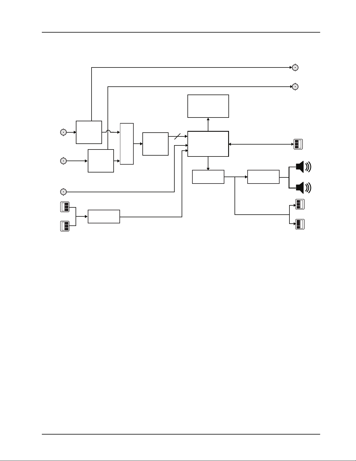
Functional Block Diagram................................................................................................... 1-3
User Interfaces ..................................................................................................................... 1-4
DashBoard Control System ................................................................................... 1-4
Controls on the Physical Panel.............................................................................. 1-4
Installation 2
Before You Begin ................................................................................................................ 2-2
Static Discharge..................................................................................................... 2-2
Unpacking.............................................................................................................. 2-2
Front Panel Overview .......................................................................................................... 2-3
Rear Panel Overview ........................................................................................................... 2-4
Physical Installation............................................................................................................. 2-6
Installation Requirements...................................................................................... 2-6
Power Supplies ...................................................................................................... 2-6
To connect the power cables for the MB-652-DUO ............................................. 2-6
Ethernet Cabling for the MB-652-DUO................................................................ 2-7
SDI Cabling........................................................................................................... 2-7
AES Input Cabling ................................................................................................ 2-7
Analog Input Cabling ............................................................................................ 2-7
Configuring the DIP Switches ............................................................................................. 2-8
Setting the IP Address ........................................................................................... 2-8
Master Password Override .................................................................................... 2-8
SW4 ....................................................................................................................... 2-8
Configuration 3
Using the Front Panel Display ............................................................................................. 3-2
Using DashBoard................................................................................................................. 3-4
To launch DashBoard............................................................................................ 3-4
To access the MB-652-DUO interface .................................................................. 3-4
Using a Master Password in DashBoard.............................................................................. 3-5
Setting the Master Password ................................................................................. 3-5
Setting the DIP Switch .......................................................................................... 3-5
To set a new master password for the MB-652-DUO........................................... 3-5
Accessing a MB-652-DUO ................................................................................... 3-6
To use a valid user account ................................................................................... 3-6
To use the Master Password.................................................................................. 3-6
Network Configuration ........................................................................................................ 3-7
Before You Begin.................................................................................................. 3-7
Automatic Configuration using DHCP ................................................................. 3-7
To establish communications with the MB-652-DUO.......................................... 3-7
Custom User Configuration via DashBoard.......................................................... 3-7
To configure the network settings via DashBoard ................................................ 3-7

ii • Contents MB-652-DUO User Manual (Iss. 02)
Audio Configuration ............................................................................................................3-9
Channel Source Selection ...................................................................................... 3-9
Mode Selection ...................................................................................................... 3-9
Adjusting the EQ Levels........................................................................................ 3-9
To adjust an equalizer band ................................................................................... 3-9
Line Out Control.................................................................................................. 3-10
Monitoring the Loudness Value......................................................................................... 3-11
Software Upgrades ............................................................................................................. 3-12
Upgrade Components .......................................................................................... 3-12
Upgrade Overview............................................................................................... 3-12
Before You Begin ................................................................................................ 3-13
Upgrading the DashBoard Connect Software...................................................... 3-13
To upgrade the DashBoard Connect software ..................................................... 3-13
Upgrading the Monitoring Bridge Software, FPGA, and DSP ........................... 3-13
To upgrade the monitoring bridge software ........................................................ 3-13
To upgrade the FPGA.......................................................................................... 3-14
To upgrade the DSP............................................................................................. 3-14
Upgrading the Auxiliary Inputs Software and FPGA.......................................... 3-14
To upgrade the auxiliary inputs software ............................................................ 3-15
To upgrade the auxiliary inputs FPGA ................................................................ 3-15
DashBoard Menus 4
Network Connect Interface .................................................................................................. 4-2
Device Tab............................................................................................................. 4-2
Network Status Tab ............................................................................................... 4-2
Network Tab .......................................................................................................... 4-3
MB-652-DUO Interfaces ..................................................................................................... 4-4
Status Tab .............................................................................................................. 4-4
Product Tab............................................................................................................ 4-4
LKFS Tab .............................................................................................................. 4-4
Settings Tab ........................................................................................................... 4-5
Equalizer Tab......................................................................................................... 4-6
Default Values ....................................................................................................... 4-6
MB-AUX-DUO Interfaces................................................................................................... 4-7
Status Tab .............................................................................................................. 4-7
Product Tab............................................................................................................ 4-7
Settings Tab ........................................................................................................... 4-7
Specifications 5
Technical Specifications ...................................................................................................... 5-2
Service Information 6
Troubleshooting Checklist ................................................................................................... 6-2
Warranty and Repair Policy ................................................................................................. 6-3
In Case of Problems............................................................................................... 6-3

MB-652-DUO User Manual (Iss. 02) Introduction • 1–1
Introduction
In This Chapter
The following topics are discussed:
• Overview
• Functional Block Diagram
• User Interfaces
A Word of Thanks
Congratulations on choosing a Ross Video MB-652-DUO Monitoring Bridge. Thank you for
joining the group of worldwide satisfied Ross Video customers!
Should you have a question pertaining to the installation or operation of your MB-652-DUO,
please contact us at the numbers listed on the back cover of this manual. Our technical support
staff is always available for consultation, training, or service.

1–2 • Introduction MB-652-DUO User Manual (Iss. 02)
Overview
The MB-652-DUO Monitoring Bridge is a compact, 2RU audio monitoring bridge for embedded
audio, with AES and analog audio. Designed to meet the demands of broadcast audio monitoring
requirements, the MB-652-DUO is capable of de-embedding up to 16 channels of audio from an
incoming SDI signal. The audio monitoring bridge provides both visual and aural monitoring
with built-in front panel display and speakers.
The 16 digital VU/PPM meters monitor all 16 channels of embedded audio, while an intuitive
control surface allows for easy channel source and mode selection for the built-in speakers. A
meter and numerical display provides loudness measurements according to ITU1770/1771
LKFS. Additional information such as true peak, input signal data and type are also displayed on
screen.
High quality, full-range speakers, along with a high performance class D stereo amplifier, offer
excellent sound quality suitable for any monitoring environment. The front panel also includes a
volume control and a 1/4 inch headphone jack. The rear of the MB-652-DUO provides two SDI
inputs with reclocked SDI outputs, AES and analog audio inputs, and two channels of analog
audio outputs.
Features
The following features come standard on the MB-652-DUO:
• Two 3G/HD/SD SDI inputs
• Two reclocked SDI outputs
• One analog input
• One AES input
• One stereo monitor output
• Left, Right, SUM, Left Total/Right Total (Lt/Rt) downmix modes
• Push to Mute rotary shaft encoder
• High quality 1/4” long-frame headset jack
• 16 VU/PPM bar graph meters
• Provides ITU 1770/1771 LKFS measurements
• Full range speakers
• Class D power amplifier

MB-652-DUO User Manual (Iss. 02) Introduction • 1–3
Functional Block Diagram
Figure 1.1 outlines the workflow of the MB-652-DUO.
Figure 1.1 MB-652-DUO — Simplified Block Diagram
VFD
16 VU/Peak Meters
LKFS Meter
16
CHANNELS
DAC
SDI OUT 1
SDI OUT 2
Amplifier
SDI IN 1
SDI EQ
and
Reclock
AES IN
MON OUT
GPIO
ANALOG
IN
SDI IN 2
16 Channel
DMX
SDI
Input
Select
SDI EQ
and
Reclock
Channel Select
Sum/Downmix
Loudness Meter
ADC

1–4 • Introduction MB-652-DUO User Manual (Iss. 02)
User Interfaces
The MB-652-DUO is intended to be controlled via the DashBoard client software, as well as
through the physical controls on the panel.
DashBoard Control System
The DashBoard client software enables you to monitor and configure the MB-652-DUO from a
computer. The DashBoard software is available for download from our website.
The MB-652-DUO includes three DashBoard interfaces: Network Connect, MB-652-DUO, and
MB-AUX-DUO. These interfaces are accessed by expanding the MB-652-DUO node in the
DashBoard Tree View and selecting the appropriate sub-node. The Network Connect interface
enables you to set up ethernet communications, and monitor those communications. the
MB-AUX-DUO interface shows status of the second SDI input. The MB-652-DUO interface
includes operational controls for the physical panel such as selecting the input source for the
speakers and adjusting the volume level for the speakers.
For More Information on...
• configuring the MB-652-DUO for network communication, refer to the section
“Network Configuration” on page 3-7.
• menus in DashBoard for the MB-652-DUO, refer to the chapter “DashBoard Menus” on
page 4-1.
• installing and using DashBoard, refer to the DashBoard User Manual.
Controls on the Physical Panel
The front panel of the MB-652-DUO provides the ability to monitor the LKFS and true peak
values, the input signal format, and meters that represent VU/PPM data and loudness
measurements. Buttons are provided to route audio sources to the speakers, selecting the
operating mode, and volume control.
The rear panel provides connections for the power supply, BNCs for the SDI inputs and outputs, a
BNC for the AES input, and 3-pin blocks for analog audio in and out.
For More Information on...
• the control and monitoring features of the front panel, refer to the section “Front Panel
Overview” on page 2-3.
• the connections provided on the rear panel, refer to the section “Rear Panel Overview”
on page 2-4.

MB-652-DUO User Manual (Iss. 02) Installation • 2–1
Installation
In This Chapter
This chapter provides instructions for the physical installation of your MB-652-DUO, and basic
cabling for the MB-652-DUO.
• Before You Begin
• Front Panel Overview
• Rear Panel Overview
• Physical Installation
• Configuring the DIP Switches

2–2 • Installation MB-652-DUO User Manual (Iss. 02)
Before You Begin
Before you begin, ensure to review the following sections.
Static Discharge
Throughout this chapter, please heed the following cautionary note:
Unpacking
Unpack each MB-652-DUO you received from the shipping container and ensure that all items
are included. If any items are missing or damage, contact your sales representative or Ross Video
directly.
ESD Susceptibility — Static discharge can cause serious damage to sensitive
semiconductor devices. Avoid handling circuit boards in high static environments
such as carpeted areas and when synthetic fiber clothing is worn. Always exercise
proper grounding precautions when working on circuit boards and related equipment.

MB-652-DUO User Manual (Iss. 02) Installation • 2–3
Front Panel Overview
This section briefly summarizes the features of the front panel.
Figure 2.1 MB-652-DUO — Front Panel
1. Input Select Buttons
This column of three push-buttons enable you to specify which input signal to monitor via the
Display Panel. Choose from the following:
•SDI 1 — selects SDI input 1.
•SDI 2 — selects SDI input 2.
•Analog/AES — when active, Source Select 1 is the analog audio input, Source Select 5 is
the AES input.
2. Display Panel
This vacuum fluorescent display panel displays the audio meters and input signal information.
The following information is displayed:
• 16 bar graph VU/PPM meters
• a bar graph meter that reports LKFS ITU 1770-3/1771 loudness measurements
• a numerical readout of the LKFS and true peak measurement
• the input signal format
3. Volume Control
Turn the knob to control the volume. Push the knob to mute the audio.
4. Source Select Buttons
This row of eight push-buttons enable you to route the corresponding source to the speakers of
the MB-652-DUO. Refer to the section “Channel Source Selection” on page 3-9 for details.
5. Mode Select Buttons
This row of four push-buttons enable you to quickly specify the operating mode of the
MB-652-DUO. Refer to the section “Mode Selection” on page 3-9 for details.
6. Headset Jack
This is a long-frame 1/4” headset jack. When in use, the internal speakers of the MB-652-DUO
are muted.
1) Input Select Buttons 3) Volume Control 5) Mode Select Buttons
2) Display Panel 4) Source Select Buttons 6) Headset Jack
5
SDI IN MONITOR
1 2 3 4 5 6 7 8 L R SUM Lt/Rt
VOLUME
HEADSET
4
Monitoring Bridge | MB-652-DUO
1 2 3
6
SDI 1
SDI 2
ANALOG/
AES

2–4 • Installation MB-652-DUO User Manual (Iss. 02)
Rear Panel Overview
This section briefly summarizes the features of the rear panel.
Figure 2.2 MB-652-DUO — Rear Panel
1. SDI IN BNCs
Each SDI IN BNC receives an 3G/HD/SD SDI input signal.
2. SDI OUT BNCs
Each SDI OUT BNC outputs a reclocked copy of the SDI input signal.
3. MONITOR Ports
These connectors provide analog audio. For a -20dBFS input, there will be a +4dBu output.
4. GPIO Port
Shorting the I pin to the G pin will mute the front speakers, and the audio level on the rear
monitor ports will be controlled by the front volume knob.
5. DIP Switches
SW1 and SW2 are used in conjunction with the DashBoard menus to set the IP Address of the
MB-652-DUO. Refer to the section “Configuring the DIP Switches” on page 2-8 for details.
SW3 is used to override the Master Password for the MB-652-DUO. This password limits access
to the MB-652-DUO.
6. ETHERNET Port
Each MB-652-DUO includes an Ethernet port on the rear panel that is used for communication
with DashBoard and software upgrades via DashBoard.
7. Power Supply Connections
These are the connectors for the primary (PSU1) and optional redundant (PSU2) supplies.
1) SDI IN BNCs 5) DIP Switches 9) AES IN BNC
2) SDI OUT BNCs 6) ETHERNET Port 10) ANALOG IN Connectors
3) MONITOR Ports 7) Power Supply Connections
4) GPIO Port 8) Power Cord Bracket Inserts
Note — If replacement 3-pin plugs are required, contact Ross Technical Support and
order Ross part number 30-01089.
IN 2
IN 1 OUT 1
OUT 2
AES IN
2 3 4 7
8910
1 65
ETHERNET
GPIO
PSU1 PSU2
MONITOR
ANALOG IN
SDI

MB-652-DUO User Manual (Iss. 02) Installation • 2–5
8. Power Cord Bracket Inserts
Install the provided brackets to help retain the power cords to the MB-652-DUO chassis.
9. AES IN BNC
This BNC is used for a 48kHz AES signal. This connection is internally terminated into 75ohms.
10. ANALOG IN Connectors
These connectors are used for line level analog audio inputs. Balanced signals are on 3-pin
pluggable connectors.
For More Information on...
• power supplies for the MB-652-DUO, refer to the section “Power Supplies” on
page 2-6.
• MB-652-DUO power consumption, refer to the section “Technical Specifications” on
page 5-2.

2–6 • Installation MB-652-DUO User Manual (Iss. 02)
Physical Installation
The MB-652-DUO mounts in the rack frame by means of four rack screws fastened through the
front mounting ears. This should normally be sufficient to carry the load, including the weight of
accompanying cables. Note that the MB-652-DUO installs in a standard 19” rack.
Installation Requirements
Keep the following in mind when installing your MB-652-DUO:
• Install the MB-652-DUO for maximum stability during operation and in such a way as to
allow adequate ventilation.
• The MB-652-DUO cannot be sealed in a closed container and must be installed in free air
space where the ambient temperature is monitored and controlled to not exceed 40°C
(104°F).
• Ensure that adequate space exists in front and behind the MB-652-DUO and on both
sides of the frame for airflow.
• The location of the MB-652-DUO should be accessible, dry, and dust-free.
Power Supplies
The MB-652-DUO comes standard with one power supply (PS-MB-650) and one A/C power
cable. A redundant power supply is available as an option. The PS-MB-650 power supply is a
power factor corrected supply, capable of working with all world AC standards (100-240V).
Contact your Ross Video sales representative to order a spare or redundant power supply.
This section includes information for connecting the power cables for the MB-652-DUO.
To connect the power cables for the MB-652-DUO
1. For each power cable, install the provided cable clamp (929-006R) and machine screw
(850-005R) to help retain the power cable connectors to the rear of the MB-652-DUO
chassis. These clamps and screws are included in the shipping container with the
Monitoring Bridge.
2. Connect the DC plug to the power jack located on the rear panel of the MB-652-DUO.
Refer to Figure 2.2 for power connection location.
3. Connect the line cord to the PS-MB-650 power supply.
4. Connect the AC cord to an AC outlet.
Table 2.1 Frame Dimensions
Model Rack Units Height Depth Width
MB-652-DUO 2 RU 3.5” (8.89cm) 8.5” (21.59cm) 19” (48.26cm)
Warning Hazardous Voltages — The safe operation of this product’s external
power supply requires that a protective earth connection be provided. This protective
earth is provided by the grounding conductor in the equipment's supply cord. To reduce
the risk of electrical shock to operator and service personnel, this ground conductor must
be connected to an earthed ground.
Warning — In some countries, it may be necessary to supply the correct mains supply
cord. Use only an approved IEC 320 C-13 type A/C line cord rated for a minimum 10A at
250V and certified for the country of use.

MB-652-DUO User Manual (Iss. 02) Installation • 2–7
Ethernet Cabling for the MB-652-DUO
The exact steps for connecting to your facility via an ethernet network depends on the network
requirements of your facility.
Contact your IT Department before connecting to your facility network to ensure that there are no
conflicts. They will provide you with an appropriate value for the IP Address, Subnet Mask, and
Gateway for the MB-652-DUO.
You will require a standard network CAT-5 cable to connect the MB-652-DUO to your facility
network. Ross Video does not supply this cable.
SDI Cabling
The rear panel includes two SDI IN BNCs and two SDI OUT BNCs.
AES Input Cabling
The rear panel includes one AES IN BNC.
Analog Input Cabling
The MB-652-DUO provides two sets of 3-pin audio terminal blocks each with a removable
connector. Each connector has locations for the positive, negative, and grounded wires of a
balanced audio cable.
For More Information on...
• the location of the ANALOG IN connector, refer to the section “Rear Panel Overview”
on page 2-4.

2–8 • Installation MB-652-DUO User Manual (Iss. 02)
Configuring the DIP Switches
This section briefly summarizes the DIP Switch settings on the MB-652-DUO. Figure 2.3 shows
the DIP Switches in the UP position.
Figure 2.3 DIP Switches — Set to the UP Positions
Setting the IP Address
SW1 and SW2 are used in conjunction with the DashBoard menus to set the IP Address of the
MB-652-DUO. Refer to Table 2.2 for DIP Switch positions. For information on configuring the
network settings for your MB-652-DUO, refer to the section “Network Configuration” on
page 3-7.
Master Password Override
SW3 is used to override the Master Password and allows a user to reset the Master Password.
Refer to the section “Using a Master Password in DashBoard” on page 3-5 for details.
•UP — This is the recommended position. A user-specified Master Password is used. The
default password is password. It can be changed using DashBoard as outlined in the
section “Setting the Master Password” on page 3-5.
•DOWN — This position is used to recover a lost Master Password. The user-specified
password is temporarily ignored, and the default value of password is used.
SW4
SW4 is not implemented at this time and should be left in the UP position.
Table 2.2 SW1 and SW2 Positions
SW1
Position
SW2
Position
Controlled via
DashBoard Descriptions
UP UP
The MB-652-DUO network settings can be set by
the user from the DashBoard Network taba.
(default)
a. DHCP Mode is assumed until the user changes the settings in DashBoard.
UP DOWN The MB-652-DUO network settings are
automatically assigned (DHCP Mode).
DOWN UP The MB-652-DUO IP Address is set to 192.168.2.1
and the Subnet Mask is set to 255.255.255.0.
DOWN DOWN The MB-652-DUO IP Address is set to 10.1.2.1.
and the Subnet Mask is set to 255.255.255.0.
1342

MB-652-DUO User Manual (Iss. 02) Configuration • 3–1
Configuration
In This Chapter
This chapter provides instructions to configure basic communications for your MB-652-DUO.
The following topics are discussed:
• Using the Front Panel Display
• Using DashBoard
• Using a Master Password in DashBoard
• Network Configuration
• Audio Configuration
• Monitoring the Loudness Value
• Software Upgrades

3–2 • Configuration MB-652-DUO User Manual (Iss. 02)
Using the Front Panel Display
This section provides a brief summary of the display panel located on the front of the
MB-652-DUO. From this panel you can monitor the MB-652-DUO.
Figure 3.1 MB-652-DUO Front Panel — Display
1. Audio Channel Bar Graph
This sixteen channel bar graph represents the VU/PPM meter where reference can be -20dBFS
(the default value) or -18dBFS. This value can be set in DashBoard via the Settings tab as
outlined in Tabl e 4.7 on page 4-5.
2. FAST Bar Graph
This ITU 1770-3 LKFS bar graph reports the FAST 1 second integration time.
3. Long Term Readout Time
This value is configurable via the options on the LKFS tab in DashBoard.
• ITU 1770 LKFS non-gated moving variable. (1 to 30sec)
• ITU 1770-2 LKFS gated moving loudness (LT). (30sec)
• ITU 1770-2 LKFS gated window (LT). (1-1200sec)
4. True Peak Readout
This value is the ITU 1770-3 LKFS numerical read-out of the true peak (PK).
5. Signal Data Display
This area includes the following fields:
•SIG field — Displays the type of SDI signal.
•GRP field — Indicates which groups of audio are present.
•RST field — Represents the minute reset timer and is configured via the Front Panel
Display options on the LKFS tab in DashBoard as follows:
› This field is reset each time you select a different source.
›If the Front Panel Display is set to Var Win, it will display the window set time.
›If the Front Panel Display is set to Gated Win, a fixed 30sec window will be
indicated.
›If the Front Panel Display is set to Integrated, it will count to the Gate Time value
(on the LKFS tab in DashBoard), and stop.
1) Audio Channel Bar Graph 3) Long Term Readout Time 5) Signal Data Display
2) FAST Bar Graph 4) True Peak Readout 6) Speaker Volume
SDI IN MONITOR
1 2 3 4 5 6 7 8 L R SUM Lt/Rt
VOLUME
HEADSET
SDI 1
SDI 2
ANALOG/
AES 1FAST INT LKFs PEAK—— —2345678dB
SIG:
GRP:
RST:
720P
1234
13:41
-20 -06
4
4
3
1 5 6
2
Other manuals for MB-652-DUO
1
Table of contents
Other Ross Media Converter manuals

Ross
Ross GearLite ADR-9039 User manual

Ross
Ross GearLite DMX-9259-A User manual

Ross
Ross NEWT-IPX User manual

Ross
Ross MB-651 User manual

Ross
Ross ADC-8733A User manual

Ross
Ross ASI-310 User manual

Ross
Ross ADC-8732B User manual

Ross
Ross Opengear UDC-8625A Series User manual

Ross
Ross DAC-8418-A User manual

Ross
Ross MB-652 User manual

Ross
Ross openGear GPI-100 User manual

Ross
Ross ADC-8432 User manual

Ross
Ross XPression Operating manual

Ross
Ross openGear DAC-8416 User manual

Ross
Ross DAC-8013A User manual

Ross
Ross UltraChrome HR User manual

Ross
Ross AirCleaner-2 User manual

Ross
Ross YOYAGER X1 Operating manual

Ross
Ross XPression User manual

Ross
Ross openGear GPI-100 User manual