Rossi DZ GHT9 User manual

Smart Products
GHT Sliding Line
KXGHT
High flow
SIA 30/ XP20WD FAAC
Installation
1st - Observe if the gate is sliding freely along its entire route, observing
the support guide, rail, stops and pulleys, if not, correct it before installing
the automator.
2nd - Provide a power and grounding point, passing a conduit, starting
from the automator to the power panel with a 10A bipolar circuit breaker.
NOTE: It is mandatory to install a disconnection device (bipolar
circuit breaker with minimum contact opening equal to 3mm)
which must be incorporated into the attached wiring. 3rd - Provide
the means by which you want to secure the automator.
• Concrete base • Metal base • French hand (air base) never upside
down.
Use the measurements in the manual to mark the location of the screws.
4th - Place 2mm spacers (Ex. washers) on the base, screw the
automation device on the spacers and put the actuator in manual mode.
5th - Close the gate, support the rack on the gear and attach the bar to
the gate with welding or screw, every 30 cm.
6th - After the racks are attached, remove the spacers placed on the
base and attach the automator again, and check the spaces between the
rack and the gear.
NOTE: " The spacers placed at the beginning of the attaching of the racks
serve to give the mandatory minimum height of 2mm between the rack
and the external gear of the automator. “
NOTE: " Failure to observe this distance can cause wear on the internal and
external gears of the automator or the rack to break when the automator
starts."
7th - Adjust the limit switches in FA open and FF closed mode, placing a
magnet on each end of the rack angle, observing the polarity of each magnet
between the open and closed gate.
NOTE: " The magnets must always be attached to the angle, even during
the opening and closing adjustments to avoid damage to the control
panel"
8th - Attaches the control unit to the support guide inside the automator
(instructions for attaching Page2).
9th -HALL sensor limit switch
The hall sensor identifies the polarity of the magnets, north and south.
(instructions Page 6)
NOTE: For bench tests, it must simulate the movement of the magnet
installed in the gate, remembering that when activating the control, the
limit switch must be active.
When installing and adjusting the magnets, in the first two commands,
the control unit must recognize the FA and FF magnets.
10th - It is MANDATORY to use the Active Infrared Sensor - SIA 30 FS or XP20WD
wireless FAAC to activate the anti-trapping protection system, avoiding collision
with obstacles, accidents with people or material goods.
11th - Gates and automations need periodic maintenance and lubrication
every 6 months for proper functioning.
1support guide
Photocell x-ray
Pulleys
2
Circuit breaker
Photocell TX
Rail and Stop
345
6
Attachment points
2mm
Rev. E - COD. 14934 www.rossiportoes.com.br Pag. 1

7Attaching the control 89The encoder must be properly
affixed to the base for a perfect
operation.
Hall
Encoder
magnet
Measurements in mm
96
100
109
85
Z12
Z15
GHT Model 9 module 4 Z12
GHT9 Model module 4 Z17
GHT Model 9 module 6 Z12
GHTI Model 12 module 6 Z15
Model GHTI 16 module 6 Z12
Model GHTI 22 module 6 Z15
GHT CHAIN Model
- 1/2" Single Chain ISO/DIN 08B-1
(between 7.75mm plates and 8.51 mm roll diameter)
Active infrared sensor
INSTALLATION
- The SIA30 FS gate barrier sensor must be installed with a distance of max. 30m between Transmitter and Receiver.
- It must be at the same height and in the same alignment (when aligned the indicator LED on the receiver goes out), ideal height for installation in gates is 50cm.
-Installation should be done as close as possible to the gate.
INSTALLATION NOTES
• Do not set near plants and objects that could interrupt the SIA30 FS beam
• The transmitter and receiver cannot be installed on mobile, unstable or
in places that move easily.
• Leave the lenses always clean
• Do not install the receiver with the lens facing the sun.
CHARACTERISTICS
• Transmitter (TX) -
12Vdc Power - 30mA
Consumption
• Receiver (RX)
- 12Vdc power supply
- 25mA Consumption
• Maximum distance - 30m
• Easy alignment
• Box with sunscreen
• LED indicating activation on the RX
• Works in NA or NF mode
• NC contacts - NA Maximum chain 1A
Rx
Tx
XP20WD Wireless (FAAC product)
Photocell FAIL SAFE function. (Dip 5 leave ON) at each operating cycle the photocell is checked.
Check the product manual for channel configuration information
Rx Tx
Easy alignment
Max. 30m
0.50 m
RX CONNECTIONS
-NC COM +
XP20 WD
turn on the (-) of the RX
on the TX-post
turn on the (-) of the TX
on the GND post if not
is going to use the battery
Drilling
measure-
ments
Pg. 2
Active Infrared Sensor

Technical Characteristics / Technical Data
DZ GHT9
DZ GHT9 Turbo
DZ GHTI 16
Turbo
DZ GHTI 12 Turbo+
DZ GHTI
22
Voltage
127 / 220V
127 / 220V
220 V
220 V
220 V
Power
750 W
750 W
1,100 W
1,100 W
1,100 W
Frequency
50/60 Hz
50/60 Hz
50/60 Hz
50/60 Hz
50/60 Hz
Protection rating
IP 44
IP 44
IP 44
IP 44
IP 44
Class
I
I
I
I
I
Operating temp:
-20°C to 55°C
-20°C to 55°C
-20°C to 55°C
-20°C to 55°C
-20°C to
55°C
Rack module. / chain
M4 Z12
M4Z17/M6Z12/chain
M6 Z12 / chain
M6 Z15
M6 Z15
Opening speed
18 m/min
26 m/min
26 m/min
34 m/min
17 m/min
Warranty term
This product was designed and manufactured to fully meet the
technical specifications described in the accompanying booklet.
ÉIt is IMPORTANT that this termbe read, as well as theentire User
Manual and the product's technical specifications and instructions
for its correct installation.
INDÚSTRIAS ROSSI ELETROMECÂNICA EIRELI, in accordance
with the Law 8078/90, certifies that the product is in perfect
condition for use and fit for its intended purpose, warranting it
against any defect in design, manufacture, or material quality
defects that make it unsuitable or inadequate for its intended use,
for a period of 1 (one) year, including the legal warranty period of
90 days, from the date of issue of the Invoice to the consumer.
When the consumer faces an eventual manufacturing defect within
the warranty period, he/she must present the product, along with
the respective purchase Invoice, to a Rossi Distributor so that the
product can be evaluated and, if necessary, repaired.
The warranty will be totally void if any of the following events occur:
a) If it is found that the defect is not a manufacturing defect;
b) If it is found that the product defect was caused by misuse or
inappropriate use, unforeseeable circumstances or force majeure
(lightning, floods, floods, landslides, etc.), defect in the electrical network.
c) If it is found that the product defect is due to exposure to
chemicals, electromagnetic interference, salt spray, excessive
humidity and/or intense heat and cold;
d) If it is found that the product defect was caused by accidents,
falls, disasters, pest attacks or agents of nature;
e)If the manufacturing label has been removed from the product;
f) If the product has been tampered with and/or has been modified
by third parties not authorized by INDÚSTRIAS ROSSI
ELETROMECÂNICA EIRELI;
g) If the product suffers natural wear, due to not having been
followed correctly, and in full, the instructions for use and
maintenance contained in the User Manual;
h) If it is found that the unsatisfactory performance of the product
originates from inadequate installation, in disagreement with NBR
5410:1997 - ABNT - Brazilian Association of Technical Standards and
with the instructions that accompany the product, or in the electrical
network where it is connected (see technical specifications of the
equipment)
i) If the product is being used in an application for which it was not
designed or if it exceeds the maximum operating cycle causing the
operator to burn out or wear out internal components;
CAUTION! The installation of the product must follow the
instructions that come with the product, otherwise this warranty will
be invalidated. The expenses necessary for the installation, as well
as the purchase of materials necessary for the installation, in
addition to optional features, will be the sole responsibility of the
consumer.
CAUTION! It is essential, under penalty of invalidating this warranty,
the use of the Active infrared sensor - SIA 30 to activate the anti-
trapping protection system. The absence of this sensor can cause
collision with obstacles, accidents with people, animals or material
goods.
CAUTION! Keep children and pets away from the gate when it is
operating.
CAUTION! The product was developed for generic use, and not for
the specific purpose of each consumer. Therefore, this warranty is
limited to serving the purposes set out in the User Manual.
CAUTION! If the equipment is defective, immediately contact the
technician who installed the equipment through the address and
telephone number filled in or stamped on this certificate.
INDÚSTRIAS ROSSI ELETROMECÂNICA EIRELI reserves the
right, at any time, to modify and/or make improvements to this
product, without incurring the obligation to do the same for products
in stock or already sold.
For people's safety it is important that all instructions are followed
Look carefully at each of them:
1th - The installer must follow all the instructions contained in this manual.
2th- Keep the commands of the automatic equipment (command buttons, remote control etc.) out of the reach of children.
3th - Carry out the command operations from points where the automatic gate is visible.
4th - Use the remote controls only if you can see the automatic gate.
5th - Warning: ROSSI does not assume any responsibility for any damage caused by non-observance, at the time of installation, of the safety standards
and the laws currently in effect. NBR 5410:1997 - ABNT - Brazilian Association of Technical Standards.
6th - This manual is intended exclusively for specialized personnel who have knowledge of the manufacturing criteria and the protection devices against accidents related
to gates and motorized doors.
7 If not provided for in the electrical panel, install before this a bipolar circuit breaker type switch with minimum contact opening equal to
3mm, of a brand that complies with international standards and provide the equipment grounding.
8 For the cable section, ROSSI recommends using a minimum section of 2.5mm and also observing the laws in force in the country.
9° Keep this manual for possible future reference
10 This appliance should not be used by people (including children) with reduced physical, sensory or mental abilities, or without experience and knowledge, unless they
are supervised or instructed on use of the appliance by someone who is responsible for their safety.
11 It is recommended that children be supervised to ensure that they are not playing with the appliance.
12° The installer must inform all the information related to automatic operation, emergency unlocking and deliver the user manual with the necessary information.
13 It is mandatory to use the Active infrared sensor - SIA 30 or XP 20W, to activate the anti-trapping protection system and allow the operation of the FS central, avoiding
collision with obstacles and accidents with people or material goods.
14 Before installing the unit, check that the driven part is in good mechanical condition, correctly balanced and opens and closes correctly
15º Frequently examine the installation for imbalances and signs of wear or damage to the cables, springs and assembly. Do not use for repairs or if adjustment is required.
16 Disconnect the equipment from power when cleaning or performing maintenance.
17º Check if the temperature of the equipment is indicated for the place where it will be used.
User Manual
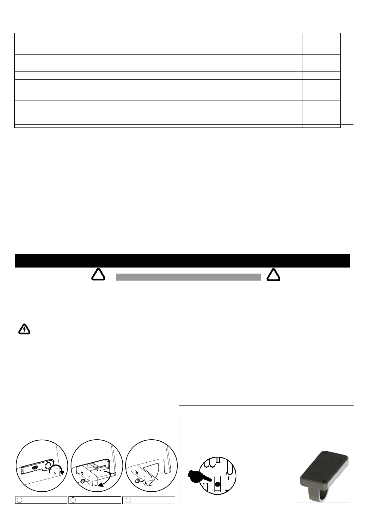
UNLOCKING FOR MANUAL OPENING
Insert and turn the key clockwise and pull the lever up to 100º.
Place and turn
the key in the sense
time
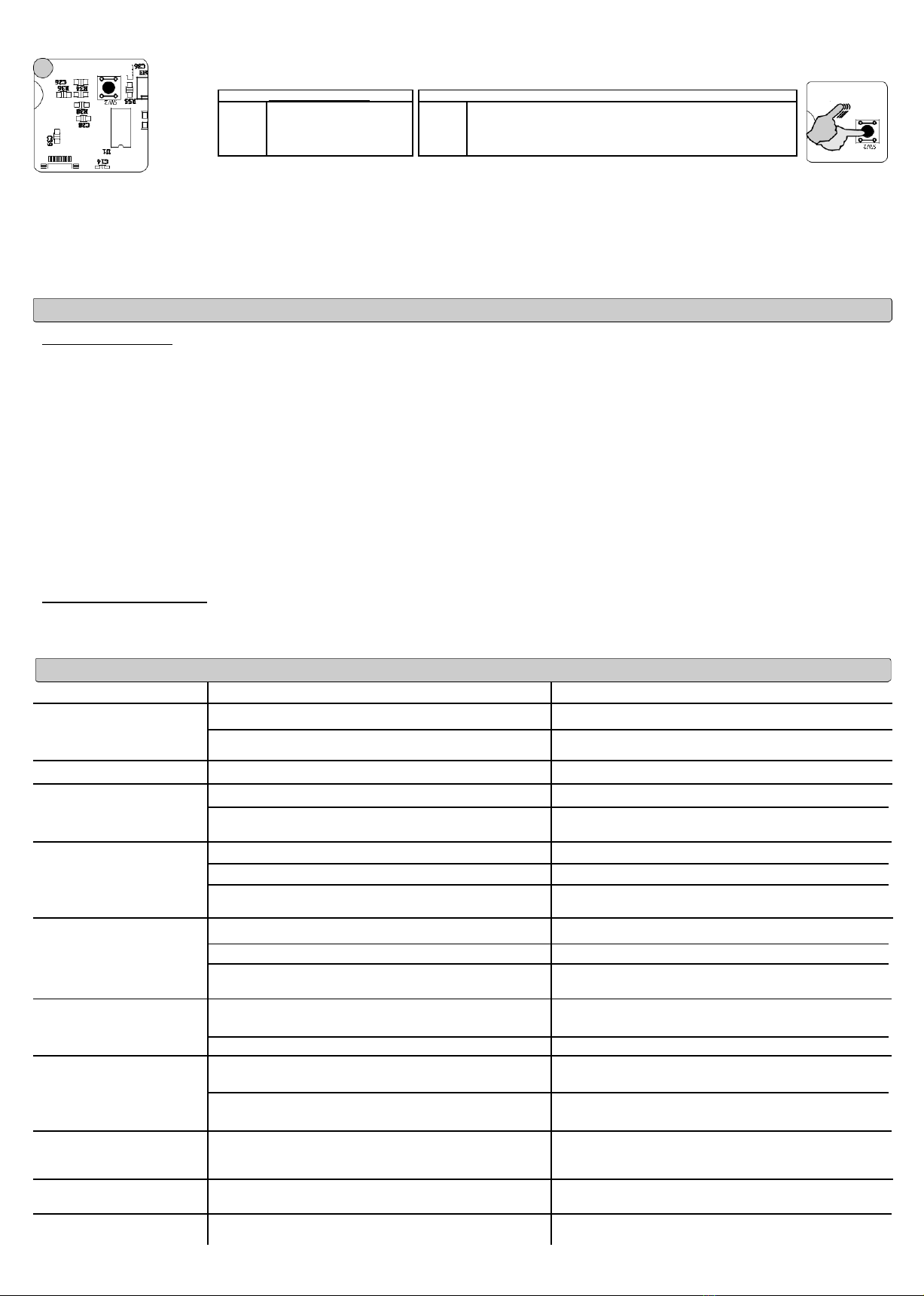
HCS REMOTE CONTROL CONFIGURATION (Rolling Code)
To add the remote control code to the command center, press and release the “LEARN” button on the
command center or Rossi receiver and immediately press one of the control buttons. To record other
buttons, repeat the operation.
Note: buttons 1 and 2 on the controller are independent.
Erase memory - If you want to erase all the codes of the remote controls in the command center, press
the “LEARN” button and keep it pressed until the “ST” led turns off.
Remote Control
1Place the key 2Pull the lever. 3Leave at 100º Control panel
Important Safety Instructions
CAUTION
LEARN

KXGHT
FUNCTION
FAIL SAFE
Characteristics
-Automatic source 90V - 240V ~ ac
-Motor with maximum power 1200W
-HALL sensor limit switch and Reed Switch
-Internal memory for 1024 removable buttons
-HCS reception system, anti-cloning
-433 Mhz reception frequency
-Residential and building function
-electronic clutch
-Delete individual passkey code
-Output for traffic light / garage light
-Input for closing photocell
-Lock output
-Adjustable automatic closing
-Opening and closing button
-Independent closing button
-Pass and close function (with photocell)
-Physical and virtual encoder
-Automatic route recognition
-Compatible with KXHI 1024 control panel
and all Rossi operators
Electronic board installation manual
Layout and Components
N - Neutral/Phase 2
F - Phase (Power Mains Input 90~240VAC)
CAP - Permanent Capacitor
U/V/W - Motor Wires (U = Core, yellow wire)
--------------------------------------------------------------------------------------------------------
12V - 12.8VDC -300mA output (for ROSSI accessories)
GND - Core for 12V Output and Accessories
FCH - Lock board Output
PHOTOCELL – Closing Photocell Input – RX TX(-) – FS Photocell
Negative SIN LIGHT – Signal Light / Garage Light
FA -Opening limit switch
CM - Core for button and limit switch
FF -Closing limit switch
BOT_A – Opening / Closing Button
BOT_F – Closing Button
GND - Core Pushbutton and Coaxial Cable Mesh for External Antenna ANT -
Coaxial Cable Core for External Antenna / Internal Antenna Wire
ADJUSTMENTS - Functional Adjustment Button / Path recognition and brake
levels
LEARN - Learn / Erase Remote Controls Button
--------------------------------------------------------------------------------------------------------------
ST - Event Indicator LED
FA - Green Led Open Gate Indicator
FF – Red Led Gate Closed Indicator
--------------------------------------------------------------------------------------------------------------
DIP-1 F.SAFE – Fail Safe Function Enabled = ON / Disabled = OFF
DIP-2 ENC / Ñ - With encoder = OFF / Without encoder = ON
DIP-3 LV-PS - Light Gate = OFF / Heavy Gate =ON
DIP-4 LOCK – Lock/Latch Enabled = ON / Disabled = OFF DIP-5 PAUSE –
Automatic Closing Enabled = ON / Disabled = OFF DIP-6 BUILDING – Building
Function Enabled = ON / Residential Function = OFF
-------------------------------------------------------------------------------------------------------------
J9 – ENCODER
Installation
1
N/F - Input 90~240VAC
Voltage input already intercepted by a 10A bipolar circuit
breaker and grounded equipment.
CAP- Permanent Capacitor
Capacitor according to motor power, wires do not have
polarity.
2
U - V - W - Motor Wires
Note: Motor with maximum power of up to 1200W
The motor has 3 wires. The core (check the label on the
motor) normally the yellow one must be connected to output
U. Outputs V and W determine the direction of rotation of the
motor (right - left).
To perform this test, leave the gate in the middle of the course
(away from the limit switches) and activate, the FF or FA LED
will flash indicating the closing or opening rotation direction.
3
Limit switches: The control unit automatically understands the two limit switches systems, by contact (reed) and/or hall without the need for programming.
NOTE: you must always use the magnet for the hall sensor; if you want to deactivate the hall sensor press 12x the
adjustment button Reed Limits CM-FA-FF
Randomly choose one end of each wire of each limit switch and one forming a core.
The other two ends that will be FF (closed) and FA (open). Connect the wires to the respective terminals FF, FA and CM (core).
Observe the position of the limit switches on the actuator so that when the gate is closed, the red LED FF lights up, and when open the green LED
FA lights up.
Hall sensor limit switch
The hall sensor identifies the polarity of the magnets, north and south. Before attaching the magnets, identify the FA and FF, to do this move the magnet over
the rack
until passing in front of the hall sensor, which will turn on the green FA or red FF LED. (If the two magnets light the same LED, invert the magnet position
which does not match the chosen Open or Closed side.)
SIN -GND - Signal light consists of interconnecting a compatible light with the gate control panel using the SIN and GND terminals.
-GND LIGHT - Garage light. to interconnect the Garage LIGHT accessory board, using the LIGHT and GND terminals.
4
BOT / GND, The Opening and Closing Pushbutton consists of installing a pulse button (bell type) on the terminal (BOT) of the control unit,
interconnecting a receiver or an external command system.
BOT_F/GND, The Closing Pushbutton consists of installing a pulse button (bell type) on the terminal (BOT_F) of the control unit or interconnecting
areceiver or an external command system. The unique function of closing the gate is activated after pressing and releasing the button.
Note: The Button is used for manual activation in watchtowers, activation through the intercom or any need for remote activation by an external button.
With SETTING at 9X (default function), BOT works as "open-to-close" and BOT_F only stops and closes after releasing the BOT _F button.
With the SETTING at 10X, BOT A only opens and BOT_F only closes after releasing the button.
5
up to
Coaxial
switchboard antenna
16cm
GND/ANT
Frequency reception antenna, connect the stripped part of the 16cm wire to the ANT terminal.
If you need a longer range, connect a 2m coaxial cable to the antenna input. - At the top of the
cable you should uncover the 16cm core.
In the connection part with the switch you must place the core in the ANT terminal and the
mesh in the GND, as in the control panel diagram.
Pg. 4
Core
Mesh
16 cm from the core
without mesh

CLUTCH
6
CLOSING PHOTOCELL
Photocell FAIL SAFE function. (Dip 1 leave ON) at each operating cycle the photocell is checked.
The photocell must be connected in Normally Closed (NC) mode, Connect the GND of the photocell's TX to the ''TX -'' terminal of the control unit.
Connection diagram WITHOUT the FS function
Connection mode compatible with previous control panels or with the Fail Safe function DISABLED (Dip 1 to OFF)
The photocell must be turned on in Normally Open (NO) mode
- It must be at the same height and in the same alignment, ideal height for installation in gates is 50cm.
- Installation should be done as close as possible to the gate.
- The certification is only valid with the use of ROSSI approved photocells: SIA 30 FS
NOTE: In the route recognition process, the barrier sensor safety system is disabled.
For connection of the XP20WD FAAC model, check the product manual
Photocell connection - FAIL SAFE
SIA 30 FS.
- Connect the photocell TX GND on
Put the
the TX- terminal of the control unit
DIP 1 to ON
Photocell FAIL SAFE function.
- The photocell must be connected to
Normally closed (NF) mode
TX-12v
GND12v CM NF
1- F.SAFE
2- ENC/Ñ
3- LV/PS
4- CLOSE
5- PAUSE
6- Building
Connection diagram WITHOUT the FS function
GND 12v GND12v CM NA
7 RESOURCES
DIP
1- F.SAFE
2- ENC/Ñ
3- LV/PS
4- CLOSE
5- PAUSE
6- Building
Enable DIP functions - To enable, set the switch to ON position
1 - F.SAFE - To enable the FAIL SAFE function set the DIP to ON; To maintain compatibility with previous versions leave DIP 1 OFF (If this process is done with
the control panel turned on, it must remove the power from the control panel and turn it back on again)
2 - ENC - WITH ENCODER-If the dip switch is in ENC mode, the control unit will only work with a Rossi physical encoder. This function was developed to work with LINE GHT
operators, using an encoder and steering wheel system to control the soft stop of the gate (VIRTUAL INVERTER, patent pending);
ÑENC - WITHOUT ENCODER - The control unit works according to models NKXH30, NKX30FS and KXHI1024FS. Moving DIP 2 between ON and OFF, the control panel performs a RESET in the functions.
The control panel must work without a physical encoder, in this mode it will use time counting to locate itself during the gate movement, not needing to program the route. This
function can be used with all traditional operators without encoder, it cannot be used in the DZ GHT line.
3 - LV - LIGHT - For automators without encoder, it works according to models KXH30 and KX30FS, For automators with encoder, it works with a short soft stop for DZ GHT .
- PS - HEAVY - For automators without encoder, it works according to models KXH30 and KX30FS, For automators with encoder, it works with a long soft stop for DZ GHT.
4 - Lock - The lock programming, when enabled, causes the control panel, after receiving an opening command, to first send a pulse to open the lock and after 0.5 seconds it starts to open the gate, the lock is
kept activated for 3.5 seconds. With the function disabled, the lock activates simultaneously with the opening of the gate for a period of 0.5 seconds. Factory default is disabled.
5 -Automatic closing (pause) - Put the pause switch in the ON position and give the opening command. When reaching the open limit switch (FA ) the ST led will start blinking at 1 second intervals, let the
desired time for the pause value elapse and give the command again. Each blink indicates 1 second elapsed until 12hrs (Ex.: If the led blinks 20 times, it means that the pause time will be 20 seconds. After
performing this operation, the pause will be programmed, every opening that occurs and takes place within the programmed time will automatically close the gate. To disable this feature, simply place the pause
switch in the OFF position. In the next command the pause will be disabled. (For this type of configuration, it is extremely important, for user safety, to use 'SIA 30 FS' barrier sensors.)
6 - Building - Every command opens the gate, which only closes by automatic closing, which will only stop at the open limit switch; if there is another command during the opening, the control panel will ignore
it. After the gate reaches the open limit switch, the automatic closing time will start counting, the gate will only close after the programmed time has elapsed. If there is a command from the remote control or BOT
button, the time will be reset, starting the count again. If the gate is closing, any command the gate stops and opens again.
Using BOT F it is possible to close the gate before the break time after releasing the contact.
(Note: In building mode the automatic closing is enabled automatically, just adjust the time in the 1st command)
Residential - Accepts all BOT control and pushbutton commands (1st - command opens, 2nd - stops, 3rd - closes).
Using BOT F it is possible to stop and close the gate after releasing the contact.
If you are using the photocell with the PASS AND CLOSE feature, a time greater than that programmed in the PASS AND CLOSE function must be set.
8
J9 - ENCODER CONNECTOR
•Before powering the board, connect the encoder wire to connector J9 and check that DIP 2 is OFF
•Check the position of the connector fitting
Note: Only required on the GHT line
RECORD REMOTE CONTROL
9
Removable Memory:
Access key recording:
•Press and release the learn button on the control panel;
•With the ST led on, press one of the control buttons at the end of the recording, it will blink and go out indicating that the programming has been accepted.
•Repeat the process to record other buttons.
Delete individual buttons:
This feature allows the coding to be erased from the control panel's memory, independently of the key code, without affecting the others. For this, the access key must be in
hand to perform this procedure.
Hold down learn while pressing the button for the key you want to delete.
Note: This operation cannot pass the maximum time of 5 seconds
Erase memory: Press the LEARN button and keep it pressed until the ST LED goes out, with this procedure you erase all the recorded codes.
This control unit has a removable memory where it can be replaced or removed if the control unit is damaged, inserting the memory IC in another control unit, the recording of the controls remains recorded.
NOTE: Check the memory Ci's fitting position with the serigraphy of the board.
CLUTCH TRIMPOT ADJUSTMENT
CLUTCH - Adjustment of engine power that can vary between 20% to 100%.
NOTE: The adjustment value is not changed during the gate movement, only after one complete opening and closing cycle
11 PASS AND CLOSE PHOTOCELL
With this function enabled, after the car leaves the route, the gate automatically closes after the programmed time, which can be 0 sec to 1 min; for this you must install a photocell and enable the function. To
enable, the gate must be closed and the FF led on, press the SET BUTTON 7 times, the ST led will flash quickly for 5sec; to record a time greater than zero, the opening command must be carried out
during the 5 sec that the ST led is blinking quickly, the gate will open and then start counting the time, to finish the count, give a command to close. To record a minimum time 0 (zero) press the SET BUTTON
7 times, the ST led will flash quickly for 5sec, after this time it records the minimum time.
Pg.05
10
LEARN

12
ADJUSTMENTS
Press and release the ADJUSTMENTS button, with intervals shorter than 1 sec. according to the desired program.
1x - BRAKE
ENC (with encoder)
Ñ ENC (without encoder)
Level 1
without brake (default)
Level 1
very weak brake for condominium GHT9 and medium for industrial
2x - BRAKE
Level 2
brake with 30% torque
Level 2
weak brake for condominiums and strong for industrial
3x - BRAKE
Level 3
brake with 60% torque
Level 3
medium brake for condominium and very strong for industrial (default).
4x - BRAKE
level 4
brake with 100% torque
level 4
strong brake for condominium - not applicable for industrial
5x - Enables the SOFT STOP function (DO NOT ENABLE IN DZI MODEL)
6x - Disables the SOFT STOP function
7x - Enables the PASS AND CLOSE function of the photocell
8x - Disables the PASS AND CLOSE function of the photocell
9x - BOT A works as "open-to-close" (just like on KXH boards), BOT F just stops and closes.
10x - BOT A only to open, and BOT_F only to close after releasing the contact.
11x - Enables the HALL limit switch sensor
12x - Disables the HALL limit switch sensor, working only the FF, CM and FA terminals of the Reed Switches.
13x - Reset, puts all settings to the original factory state, including route (default). Note: Does not erase controls.
Putting into Operation
•GHT line with encoder, to put the system into operation, follow the following 2 steps:
1 - Gate
Set DIP 2 to OFF, ENC (WITH ENCODER) and DIP 3 to LV /PS (LIGHT / HEAVY) according to your application and record a Rossi control to the control panel. Note: connect the J9 encoder terminal
2 - Setup
Press and hold the ADJUSTMENTS button for 5 seconds until the ST led starts to flash and release the button, then the automatic route recognition process starts at a slow speed; must expect a complete
opening and closing cycle. Check if the brake level meets the application
NOTE: (VERY IMPORTANT - READ):
1- Until the SETUP step 2 is done, the ST led will flash slowly and the speed will be reduced.
2 - Make sure that the magnets are positioned " Hall Limit Switch sensor" on the sliding line or the "Reed Switch Limit Switch" on the tilting and pivoting line, properly identified (FF and FA) before starting the
recognition process of the route; if there is a need to move the magnet or Reed, repeat step 2 Setup.
3 - The "Photocell" safety device will be inoperative in step 1 and 2.
4 - The Tx, pushbutton or ADJUST button commands have priority over the route recognition process. Therefore, if any of these devices is activated during the recognition process, the system will be
interrupted and the process of step 2 SETUP must be restarted.
5 - In step 2, if the gate is not at the limit switch, the plate moves the gate to a limit switch and then performs a complete opening and closing cycle
6 - If the magnet has to be repositioned, it will be necessary to redo the recognition of the path from step 2 SETUP.
7 - Parameter adjustments must be made with the gate stopped; after adjustment, perform a complete opening and closing cycle by the remote control to confirm the adjustment value.
•Automator without encoder,
1 - Gate • Check the FF and FA magnets if they are in the correct position, record a Rossi control and adjust the clutch.
• Set DIP 2 to ON, Ñ ENC (NO ENCODER). To enable soft stop press SET 5X button, DIP 3 between LV /PS (LIGHT / HEAVY) according to your application.
Malfunction Search
Malfunction
Cause
Solutions
ST led is blinking slowly, the SETUP process was not done.
Do the ''Getting Started'' process
Does not increase speed
Gate is above max weight or locked
Check the weight limit for the drive and movement
of the Gate
Does not start SETUP
Encoder off
Check J9 connector connection and functionality
Automator makes noise and
not movement
Motor connected to wrong voltage
Enter the voltage according to the motor label
Ÿ The starting capacitor is not connected to the CAP
terminal of the control panel / damaged capacitor
Ÿ Insert starting capacitor according to the voltage and
power of the motor / replace capacitor
Does not start SETUP, led FF
or FA intermittent blinking
Magnet polarity is reversed
Correctly position the FA and FF magnets
Wires V and W are reversed
Reverse the position of the V and W wires
The gate is outside the route limit start the SETUP process with the gate in the middle of the route
Magnet polarity is reversed
Correctly position the FA and FF magnets
Setup does not finish
Wires V and W are reversed
Reverse the position of the V and W wires
The remote control, SET or LEARN buttons were
triggered before the end of the process.
Start the SETUP process without pressing the buttons until
complete.
Automator does not turn on:
ST led intermittently blinking
FS function enabled and SIA 30FS photocell not installed
correctly • Check Installation of FS mode in item 6 of the manual.
SIA 30FS photocell with busy beam (obstacle)
• Unclog the beam and check wiring
Gate slamming into frame /
leaving the limit switch
The position of the limit switch has been changed after
SETUP
Check the position of the magnets and carry out the
process of Putting into Operation
The acceleration, deceleration, brakes or
Adjust the brake levels according to the weight
speeds are high for the application
and automator model
Gate closing after
pass the car Ÿ PASS AND CLOSE function enabled with photocell installed
with the pause time at 0 sec.
Disable the function by pressing the adjustment button 8
times.
FF and FA led does not light
and does not STOP the gate
Hall limit switch, has been disabled in the control unit Press the SET button 11x to enable the sensor end of
hall sensor
Does not make soft stop
DIP 2 in ON function without encoder enabled
Press SET button 5x to enable soft stop
Pg.06
ADJUSTMENTS
ADJUSTMENTS
This manual suits for next models
4
Table of contents
Other Rossi Gate Opener manuals
Popular Gate Opener manuals by other brands

ALLOMATIC
ALLOMATIC TORO 24 installation manual

HySecurity
HySecurity HTG 320-8 Installation and maintenance manual

HySecurity
HySecurity HydraSwing 40 Programming and operations manual

Entrematic
Entrematic OBBI3BH Original instruction

GiBiDi
GiBiDi KUDA 150 Instructions for installations

FAAC
FAAC S418-LE manual

CARDIN ELETTRONIC
CARDIN ELETTRONIC 200/BL202 instruction manual

Viking
Viking R-6NX Installation instructions and safety information

Mighty Mule
Mighty Mule FM402 installation manual

Schellenberg
Schellenberg SMART DRIVE 60030 manual

DoorKing
DoorKing Series 9500 Installation and owner's manual

FAAC
FAAC 741 user manual