Roth AHTR Series User manual

Installation, Operation & Maintenance:
Field-Installed Electric Heater for
RXT Series Units
P/N: 2300100902
Table of Contents:
Section 1: Model Nomenclature
Model Nomenclature..............................................................2
Section 2: Safety Labeling and Signal Words
Warnings, Cautions, and Notes..............................................2
Section 3: Introduction
Introduction, Inspection, Denition, Unit Protection ............3
Section 4: Installation
Overview, Considerations, Installation Steps ...................4 - 6
Section 5: Electrical Data
AHTR Electric Heat Electrical Data.........................................6
Section 6: Wiring Diagrams
AHTR101B / 10kW......................................................................7
AHTR151B / 15kW......................................................................8
AHTR201B / 20kW......................................................................9
Section 7: Parts Lists
AHTR101B / 10kW....................................................................10
AHTR151B / 15kW....................................................................11
AHTR201B / 20kW....................................................................12
Guide Revision Table:
Date By Page Note
August 2010 KT All First Published
P.O. Box 245
Syracuse, NY 13211
www.roth-america.com
888-266-7684
2
Roth AHTR Series Elec Heat IOM, August 2010 AHTR Series Elec Heat IOM, August 2010
AHTR Series Elec Heat IOM, August 2010
Section 1: Model Nomenclature
Section 2: Safety Labeling and Signal Words
DANGER, WARNING, CAUTION, and NOTE
The signal words Danger, Warning, Caution,
and Note are used to identify levels of hazard
seriousness. The signal word Danger is only used
on products label to signify and immediate
hazard. The signal words Warning, Caution,
and Note will be used on product labels and
throughout this manual and other manuals that
may apply to this product.
“NOTICE” Notication of installation, operation
or maintenance information which is important,
but which is NOT hazard-related.
“CAUTION” Indicates a potentially hazardous
situation or an unsafe practice which, if not
avoided, COULD result in minor or moderate
injury or product or property damage.
“WARNING” Indicates potentially hazardous
situation which, if not avoided, COULD result in
death or serious injury.
“DANGER” Indicates an immediate hazardous
situation which, if not avoided, WILL result in
death or serious injury.
“Note:” Used to highlight suggestions which will
result in enhanced installation, reliability,
or operation.
SIGNAL WORDS IN MANUALS
The signal word WARNING is used throughout
this manual in the following manner:
The signal word CAUTION is used throughout this
manual in the following manner:
Signal Words on Product Labeling
Signal words are used in combination with
colors and/or on product labels.
WARNING
CAUTION
AH 10 1 B
1
& 2
: Fa
mi
l
y
3
& 4
: Ty
p
e
5
& 6:
Capaci
ty
7:
V
o
l
tag
e
8: Rev
i
s
i
on
Family:
AH = Field Installed Electric Heater
Type:
TR = Field Installed Used on
RXT Series Models
Revision:
B = Current Revision
Voltage:
1 = 208/230V, 60Hz, 1 Phase
Capacity:
10kW
15kW
20kW
Rev.: 14 July 2010D
TR

AHTR Series Elec Heat IOM, August 2010
3
AHTR Series Elec Heat IOM, August 2010 Roth
Section 3: Introduction
INTRODUCTION
The AHTR electric heater is designed specically
for the RXT Series Geothermal Heat Pump
Unit. Engineering and quality control is built
into every electric heater assembly. Good
performance depends on proper application
and correct installation.
The information contained in this manual is
intended for use by a qualied service technician
familiar with safety procedures and equipped
with the proper tools and test instruments.
Shut OFF electric power at unit disconnect
and/or service panel before beginning the
following procedures.
UNIT PROTECTION
Protect units from damage and contamination
due to plastering (spraying), painting and
all other foreign materials that may be used
at the job site. Keep all units covered on the
job site with either the original packaging or
equivalent protective covering. Cap or recap
unit connections and all piping until unit is
installed. Precautions must be taken to avoid
physical damage and contamination which
may prevent proper start-up and may result in
costly equipment repair.
OVERVIEW
This instruction covers the physical installation
of the AHTR Series electric heat kits when
installed with the RXT Series Geothermal Heat
Pump unit.
The electric heat accessories are used for
applications of heat pump with electric heat.
Each of the unit models are approved for
use with specic electric heat accessories.
The installation instructions list the possible
combinations and other important electrical
data and limitations.
INSPECTION
Upon receipt of any geothermal accessory,
carefully check the shipment against the
packing slip and the freight company bill of
lading. Verify that all units and packages have
been received. Inspect the packaging of
each package and each unit for damages.
Insure that the carrier makes proper notation
of all damages or shortage on all bill of lading
papers. Concealed damage should be
reported to the freight company within 15 days.
If not led within 15 days the freight company
can deny all claims.
WARNING
ELECTRICAL SHOCK HAZARD
FAILURE TO FOLLOW THIS WARNING
COULD RESULT IN PERSONAL INJURY,
PROPERTY DAMAGE AND/OR DEATH.
INSTALLATION OR REPAIRS MADE BY
UNQUALIFIED PERSONS CAN RESULT
IN HAZARDS TO YOU AND OTHERS.
INSTALLATION MUST CONFORM WITH
LOCAL BUILDING CODES OR, IN THE
ABSENCE OF LOCAL CODES, WITH
NATIONAL ELECTRICAL CODE ANSI/
NFPA 70-2008 OR CURRENT EDITION.
Accessory Heater Usage
Model Description Used With
RXT Model
AHTR101B 10kW, 60Hz, 1 Phase
w/Circuit Breaker 024 - 072
AHTR151B 15kW, 60Hz, 1 Phase
w/Circuit Breaker 036 - 072
AHTR201B 20kW, 60Hz, 1 Phase
w/Circuit Breaker 048 - 072
Note: AHTR electric heaters are not
backward compatible.
Adapter and ller plates are shipped with the
indoor units to be used with electric heat as
needed depending on unit size and heater size.
Table 1: Heater Compatibility
Note: Notify Roth’s shipping department of all
damages within 15 days. It is the responsibility of
the purchaser to le all necessary claims with the
freight company.

4
Roth AHTR Series Elec Heat IOM, August 2010 AHTR Series Elec Heat IOM, August 2010
AHTR Series Elec Heat IOM, August 2010
Section 4: Installation
INSTALLATION
This instruction covers the physical installation
of the AHTR Series electric heat kits when
installed with the RXT Series Geothermal Heat
Pump Unit.
The electric heat accessories are used for
applications of heat pump with electric
heat. Each of the air handler unit models are
approved for use with specic electric heat
accessories. The installation instructions list the
possible combinations and other important
electrical data and limitations.
1. Shut OFF electrical power at unit disconnect
switch or service panel.
2. Remove the upper front panel from unit
and locate ller plate. Remove the (4) sheet
metal screws from plate. (See Figure 1)
RIGHT HAND AIRFLOW AND LEFT HAND
DOWNFLOW APPLICATION
3. If unit is going to be used for right hand
return or left hand return downow (airow)
the circuit breakers will have to be removed
and rotated 180 degrees, so the OFF position
will be DOWN when the cabinet is positioned
on the right side. This is an NEC requirement.
DO ONE BREAKER AT A TIME to make sure
wires are reconnected properly. Loosen
terminal screws on the wires. Gently pull wires
back from breaker. Remove screws securing
the breaker and rotate 180 degrees, then
reconnect the wires to breaker. Proper
torque for terminal screws is 35 inch pounds.
4. Insert the heater into the cabinet opening as
shown in Figure 1, so the heater support rod
goes into the hole in the back of the plenum.
Exercise caution to prevent damage to
heater element.
5. Secure the electric heat accessory with
four screws.
CAUTION
CUT HAZARD
FAILURE TO FOLLOW THIS CAUTION
MAY RESULT IN PERSONAL INJURY.
SHEET METAL PARTS MAY HAVE SHARP
EDGES OR BURRS. USE CARE AND
WEAR PROTECTIVE CLOTHING AND
GLOVES WHEN HANDLING PARTS.
WARNING
ELECTRICAL SHOCK HAZARD
FAILURE TO FOLLOW THIS WARNING
COULD RESULT IN PERSONAL INJURY
OR DEATH.
BEFORE INSTALLING, MODIFYING, OR
SERVICING SYSTEM, MAIN ELECTRICAL
DISCONNECT SWITCH MUST BE IN THE
OFF POSITION.
THERE MAY BE MORE THAN ONE
DISCONNECT SWITCH. LOCK OUT
AND TAG SWITCH WITH SUITABLE
WARNING LABEL.
Figure 1: Heater Installation
Representative drawing only, some models may vary in appearance.
Heater Support Rod Fits into Hole
Rotate Circuit
Breakers 180
Degrees for RH and
LH DN Airow

AHTR Series Elec Heat IOM, August 2010
5
AHTR Series Elec Heat IOM, August 2010 Roth
Section 4: Installation
LOW VOLTAGE WIRING
6. Connect the 6-Pin heater wiring harness to
the receptacle located inside the cabinet
(Top Cover). A perfect match and positive
connection must be made between the
plug and receptacle. The plug will interlock
with receptacle when properly seated.
Harness contains 24 Volts wiring.
WIRING
7. Route unit power supply through knockout
in top of unit and connect to line side of
disconnect. Connect ground wire to ground
lug. See wiring diagram label to make
connections. All line voltage connections
and ground connections MUST be made
with copper wire.
The power supply wiring MUST have
overcurrent protection. This can be either
fuses or circuit breakers. The maximum size
for the overcurrent protection is shown in the
column labeled “Max. Fuse or NEC HACR
Breaker (Amps)” in the electrical Data Table
or on the unit rating plate. Connect supply
voltage wires to the Circuit Breakers on the
heater or to the terminal block on the heater.
NOTE: Supply voltage, amperage, fuse and
disconnect switch sizes MUST conform with all
technical specications in this manual and on
the unit rating plate.
GROUNDING
8.
Permanently ground the electric heat
accessory in accordance with local codes
and ordinances and in the United States
with National Electrical Code ANSI/NFPA70-
2008 or current edition. Use a copper
conductor of the appropriate size from the
electric heat accessory ground lug, to a
grounding lug on the circuit breaker panel.
On models with more than one circuit, a
separate copper ground wire MUST be
connected for each circuit.
8. Install top front door panel.
9. Mark an “X” in the appropriate box for the
heater on the unit rating plate.
TIME DELAY MODULE
10. The time delay module stages the heater
elements for 15kW and 20kW heaters. In
most cases, all of the DIP switches should
be in the “ON” position, which will provide
a 1,023 second (approximately 17 minute)
delay between the rst and second stage
of electric heat.
For example, if all of the switches are
in the “ON” position of a 20kW heater,
only 10kW will be energized when the
thermostat calls for backup or emergency
heat. After approximately 17 minutes of
continuous demand from the thermostat,
the second bank of electric heat will
be energized, providing the full 20kW of
heat. The DIP switches may be set in any
manner that is desired.
There are 10 DIP switches that are
cumulative. In other words, starting with
the rst switch, the time delay for each
additional switch that is in the “ON”
position is added to the previous switch.
The switches are labeled 1, 2, 4, 8, 16,
32, 64, 128, 256, and 512. When all of
the switches are in the “ON” position,
all of the numbers must be added to
determine the time delay. In the case
of all switches in the “ON” position, the
delay is 1+2+4+8+16+32+64+128+256+512
= 1,023 seconds. If only 8 to 9 minutes
is desired between stages, place all
WARNING
ELECTRICAL SHOCK HAZARD
THE UNIT CABINET MUST HAVE AN
UNINTERRUPTED OR UNBROKEN
GROUND TO MINIMIZE PERSONAL
INJURY IF AN ELECTRICAL FAULT
SHOULD OCCUR. THE GROUND MAY
CONSIST OF ELECTRICAL WIRE OR
METAL CONDUIT WHEN INSTALLED WITH
EXISTING ELECTRICAL CODES.

6
Roth AHTR Series Elec Heat IOM, August 2010 AHTR Series Elec Heat IOM, August 2010
AHTR Series Elec Heat IOM, August 2010
Section 5: Electrical Data
TECHNICAL DATA (AHTR Electric Heaters only) Single Phase w/ Circuit Breaker
Heater Model Supply
Voltage
Heat
kW
Supply
Circuit
Number
Heater
kW Per
Circuit
FLA
Total
AMPS
MCA
Min
Circuit
Ampacity
Maximum
Over-
Current
Protective
Device
(AMPS.)
Recommended
Supply Wire
75°C. Copper
Ground
Wire
# of
Wires
Wire
Size
Max
Length
(Ft)
# of
wires
Min
Size
AHTR101B 240 10 Single 5 41.7 52.1 60 2 6 101 1 10
208 7.5 Single 3.75 36.1 45.1 2 6 115 1 10
AHTR151B
240 15 Mult. 1 5 20.8 26.0 30 2 10 118 1 10
240 Mult. 2 10 41.7 52.1 60 2 6 101 1 10
208 11.25 Mult. 1 3.75 18.0 22.5 30 2 10 118 1 10
208 Mult. 2 7.5 36.1 45.1 60 2 6 101 1 10
AHTR201B
240 20 Mult. 1 10 41.6 52.0 60 2 6 101 1 10
240 Mult. 2 10 41.6 52.0 60 2 6 101 1 10
208 15 Mult. 1 7.5 48.1 60.0 60 2 6 101 1 10
208 Mult. 2 7.5 48.1 60.0 60 2 6 101 1 10
but the last switch (the switch labeled
“512”) in the ON position. With 9 switches
in the “ON” position, the time delay is
1+2+4+8+16+32+64+128+256 = 511 seconds
(about 8.5 minutes). Other combinations
of switches may be used, depending upon
the desired time delay.
AIR FLOW
11. Airow requirements are different between
models. Please refer to the unit Installation
Instructions for airow set-up information.
TEMPERATURE RISE CHECK
12. Temperature rise is the difference between
the supply and return air temperatures.
NOTE: The temperature rise can be adjusted by
changing the heating CFM. Refer to the unit’s
Installation Instructions for airow information.
NOTE: The maximum outlet air temperature for
all models is 200 Degrees F (93.3 Degree C).
Section 4: Installation
AHTR Series Elec Heat IOM, August 2010
7
AHTR Series Elec Heat IOM, August 2010 Roth
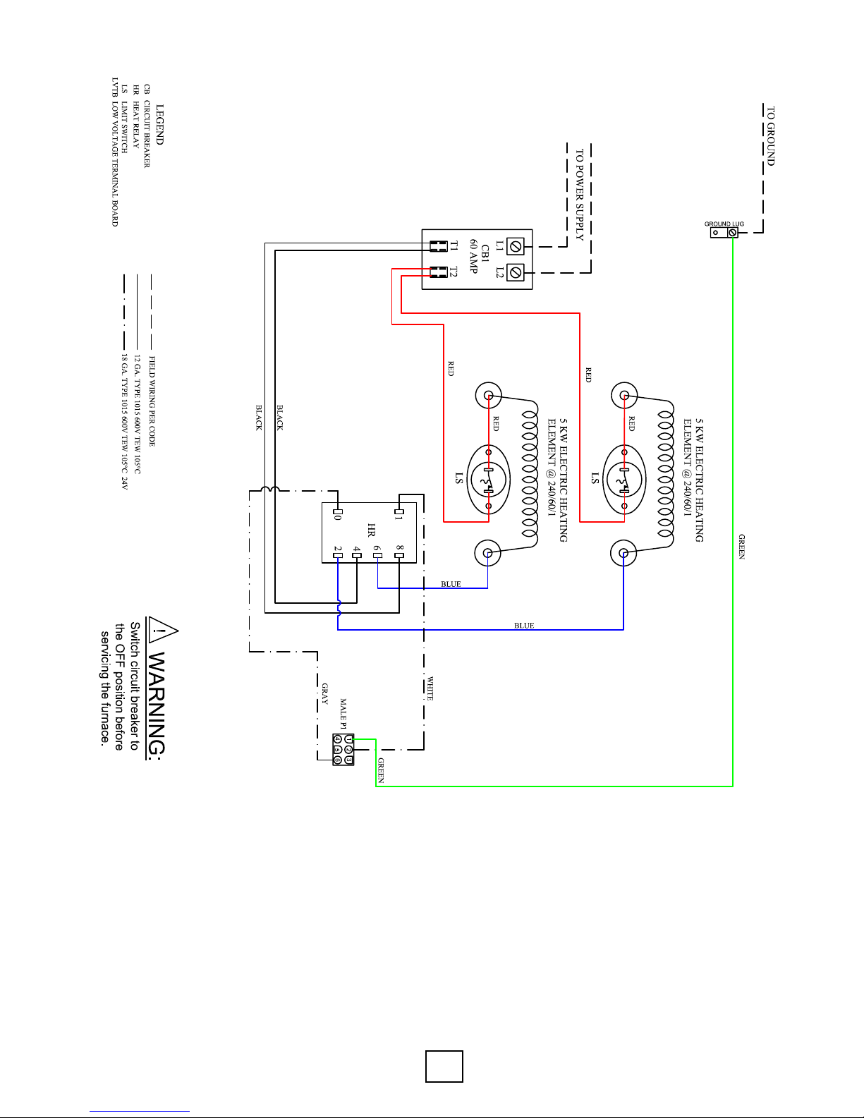
Section 6: Wiring Diagrams - AHTR101B / 10kW
8
Roth AHTR Series Elec Heat IOM, August 2010 AHTR Series Elec Heat IOM, August 2010
AHTR Series Elec Heat IOM, August 2010
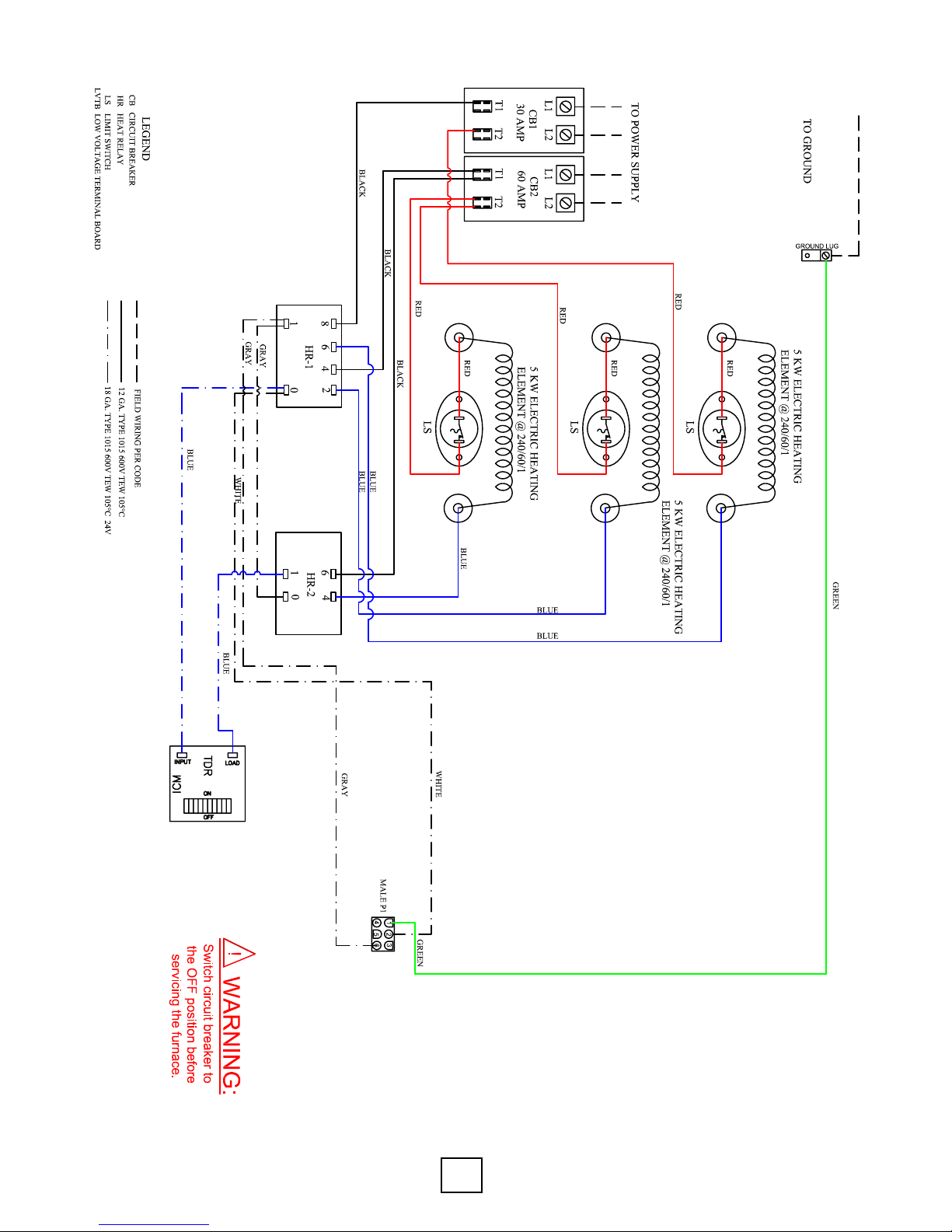
Section 6: Wiring Diagrams - AHTR151B / 15kW

AHTR Series Elec Heat IOM, August 2010
9
AHTR Series Elec Heat IOM, August 2010 Roth
Section 6: Wiring Diagrams - AHTR201B / 20kW
10
Roth AHTR Series Elec Heat IOM, August 2010 AHTR Series Elec Heat IOM, August 2010
AHTR Series Elec Heat IOM, August 2010
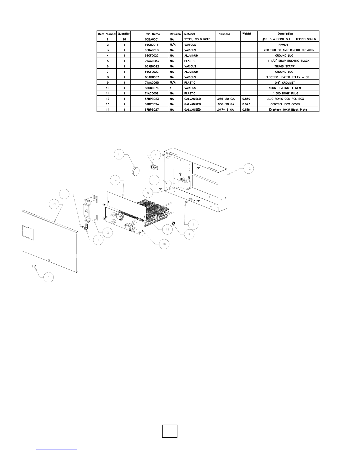
Section 7: Parts List - AHTR101B / 10kW
This manual suits for next models
3
Table of contents


