RMS-Converter
E-M-RMS-Converter-V1_4.docx
Instruction Manual
© 2018
ROTRONIC AG
Bassersdorf
Switzerland Pa e 2 of 126
Table o Contents
1
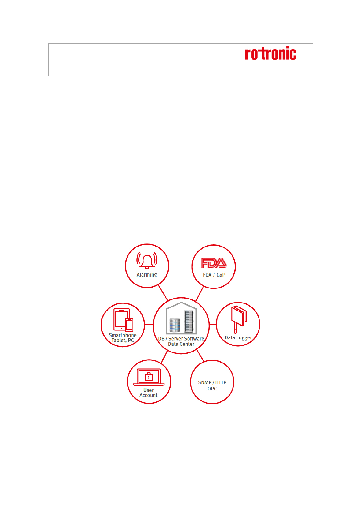
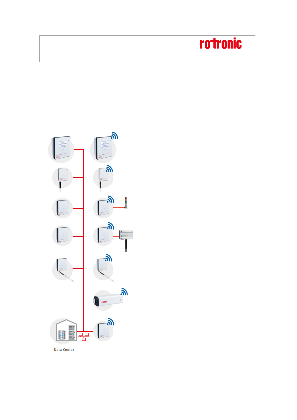
Overview ................................................................................................................................................. 4
1.1
RMS System Overview ........................................................................................................................ 4
1.2
Device Overview .................................................................................................................................. 5
2
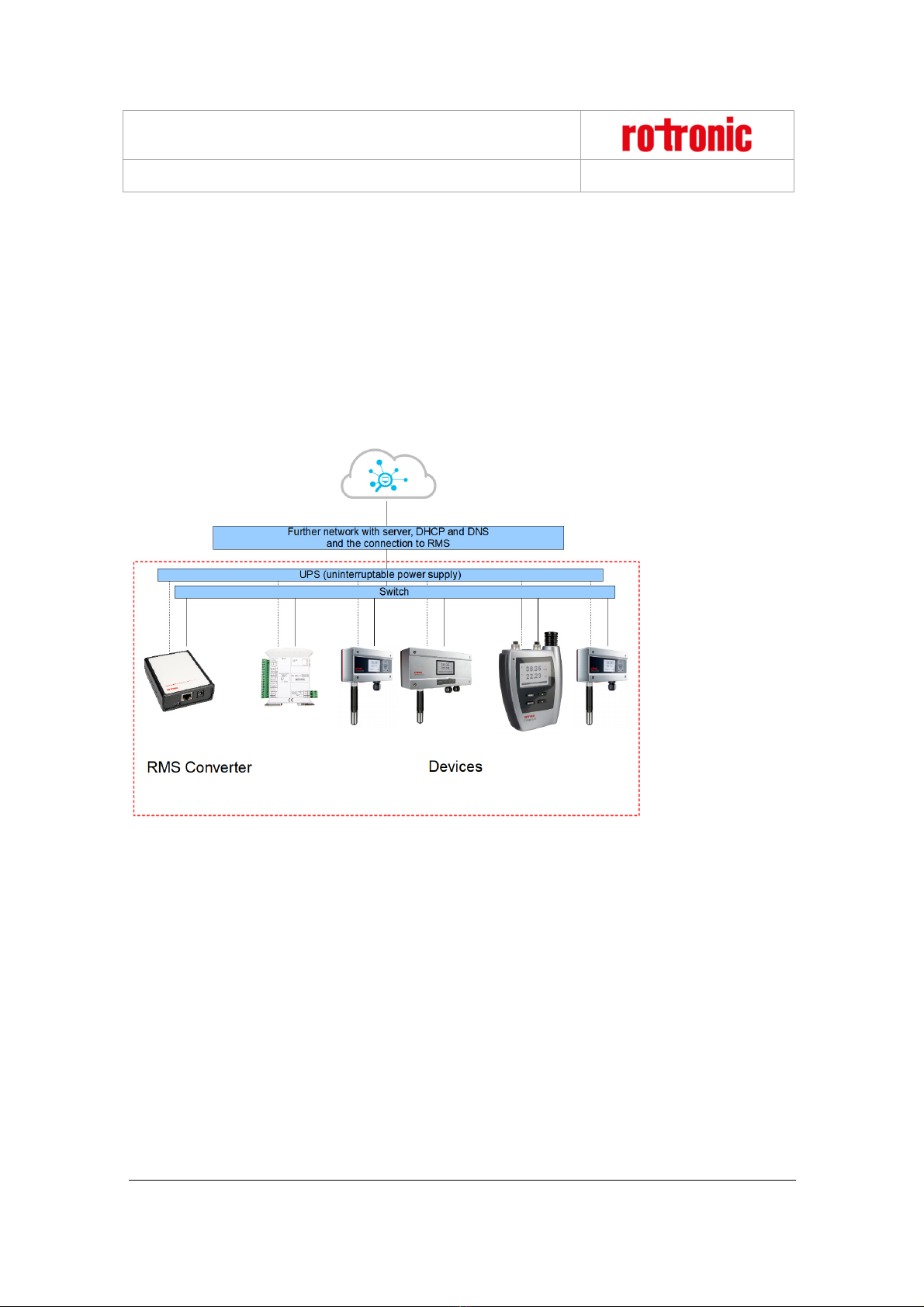
RMS-CONVERTER ................................................................................................................................. 6
2.1
General ................................................................................................................................................ 6
2.2
Power Supply ....................................................................................................................................... 6
2.3
Interface ............................................................................................................................................... 6
2.4
Limit of measurement points ................................................................................................................ 6
2.5
MS SQL database ................................................................................................................................ 6
2.6
RTC (Real Time Clock) ........................................................................................................................ 7
2.7
Data encryption .................................................................................................................................... 7
2.8
Measurement interval ........................................................................................................................... 8
2.9
Dimensions .......................................................................................................................................... 8
2.10
Function Overview ............................................................................................................................... 8
3
Installation and con iguration............................................................................................................. 10
3.1
Default confi uration .......................................................................................................................... 10
3.2
Confi uration via web browser ........................................................................................................... 10
3.3
Confi uration via RMS CONFIG software .......................................................................................... 12
3.4
Pairin of the RMS-CONVERTER ..................................................................................................... 13
3.5
Settin s of the RMS-CONVERTER .................................................................................................... 15
4
Integration o the RMS-CONVERTER into RMS ................................................................................ 16
5
Firmware update .................................................................................................................................. 18
5.1
Firmware update via RMS .................................................................................................................. 18
5.2
Firmware update with RMS CONFIG ................................................................................................. 19
6
Integration o Rotronic conventional products into RMS ................................................................ 21
6.1
General .............................................................................................................................................. 21
6.2
Inte ration of the HF5 transmitter into RMS ....................................................................................... 23
6.3
Inte ration of the HF8 transmitter into RMS ....................................................................................... 37
6.4
Inte ration of the PF4 transmitter into RMS ....................................................................................... 52
6.5
Inte ration of the PF4/5 transmitter into RMS .................................................................................... 64
6.6
Inte ration of the CRP5 clean room panel into RMS.......................................................................... 73
6.7
Inte ration of the HL-NT data lo er into RMS .................................................................................. 84
7
Integration o third party products into RMS .................................................................................... 97
7.1
General .............................................................................................................................................. 97
7.2
Inte ration of the RMS-8ADC/4RTD transmitters into RMS ............................................................... 98
7.3
Inte ration of the HL-RC data lo er into RMS ................................................................................ 111
7.4
Inte ration of the Li hthouse Apex R5 data lo er into RMS .......................................................... 118
8
Technical speci ications ................................................................................................................... 124