RS Technical Services MINI TRACTOR STANDARD User manual
Document Number 900-21806 Rev B
Design and Manufacture of Video Pipeline Inspection Systems
A full Service Company
www.rstechserv.com
M
MI
IN
NI
I
T
TR
RA
AC
CT
TO
OR
R
S
ST
TA
AN
ND
DA
AR
RD
D
M
M
Mo
o
od
d
de
e
el
l
l
3
3
32
2
2-
-
-3
3
30
0
00
0
00
0
0
O
OP
PE
ER
RA
AT
TI
IO
ON
NS
S
M
MA
AN
NU
UA
AL
L
M
M
M
a
a
a
d
d
d
e
e
e
i
i
i
n
n
n
t
t
t
h
h
h
e
e
e
U
U
U
S
S
S
A
A
A

Document Number 900-32028 Rev A 2
Table Of Contents:
Page 3 Product Information
Page 4 Technical Specifications
Page 5 Operator and Equipment Safety
Page 6 Equipment Compatibility
Page7 Accessory Kits
Page 8 Options
Page 10 Operation and System Power
Page 11 Mini Tractor Operations
Page 15 Maintenance
Page 17 Warranty
Page 18 MRA
Copyright © 2002 RS Technical Services

Document Number 900-32028 Rev A 3
Product Overview
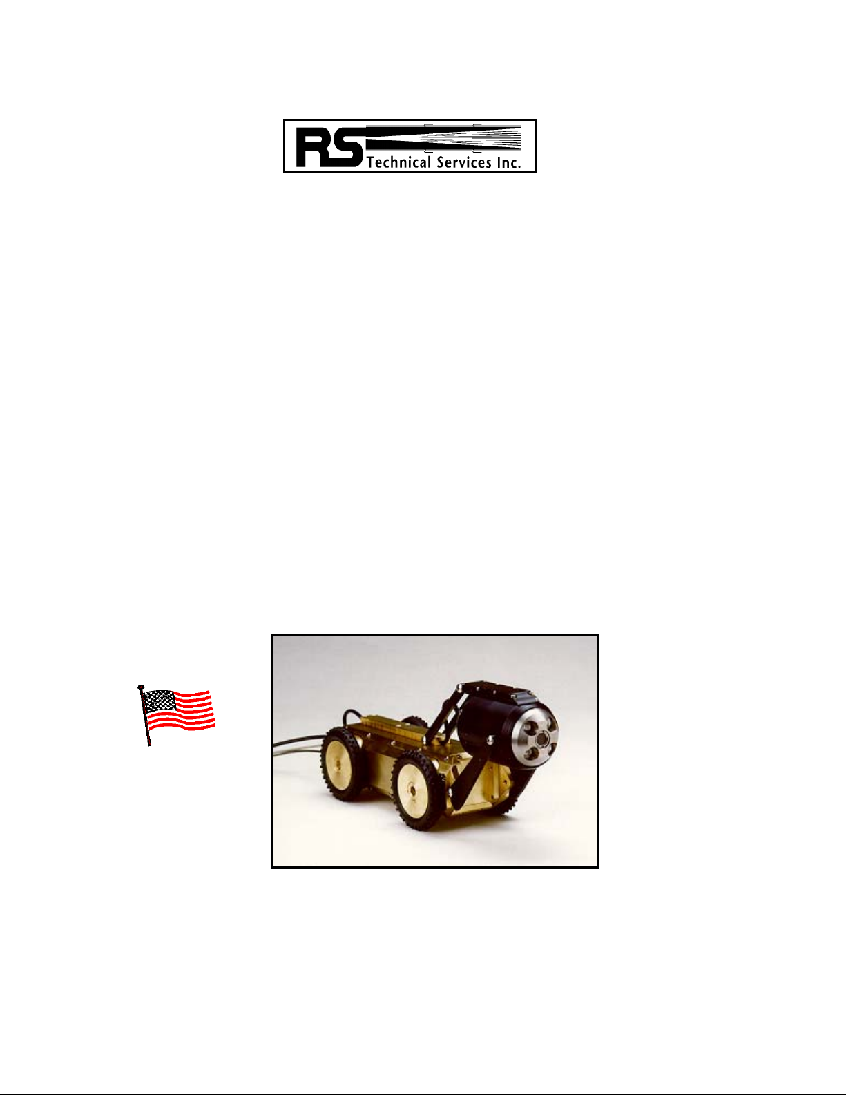
MIGHTY MINI TRACTOR, STANDARD
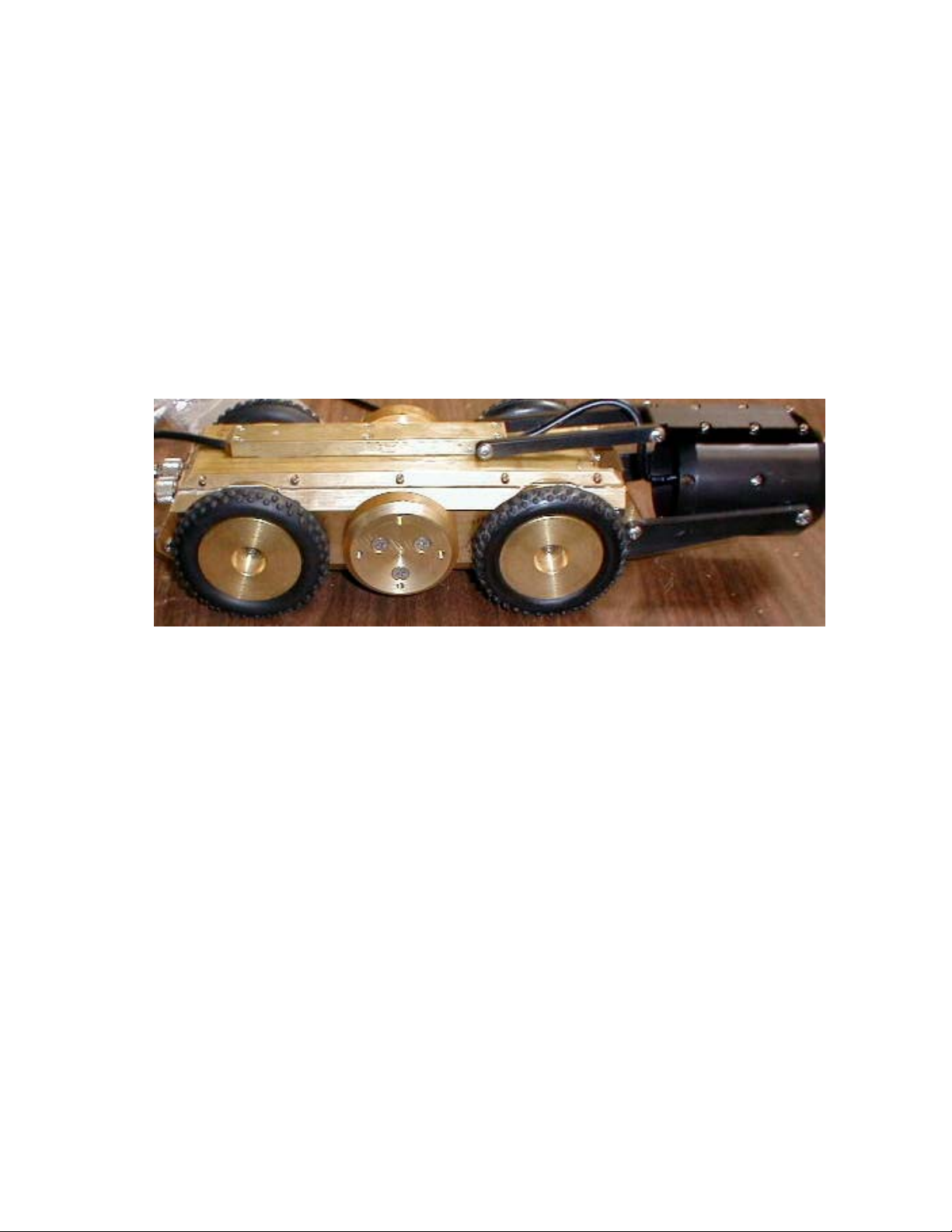
The RST Mini Tractor is a four-wheel drive inspection vehicle developed
for 4-inch lines. It has an adjustable (manual) camera mounting for central
viewing in lines up to 12 inches with an optional set of tires. The Mini Tractor
is designed to transport R.S.T. 1300 series cameras. It can be supplied with a
dedicated camera or with a dual-purpose camera used with the R.S.T. Push
Cable System. The Push Cable Cameras already in field need on a minor
factory modification to allow use of the Mini Tractor to transport them. The
camera can be used with either device.
The compact, easy to use unit is adaptable for use in sanitary sewer, storm
sewer, and water main pipelines 4 inch to 10 inches (by using the optional larger
tires). The weight of the Mini Tractor can be adjusted to improve traction if needed.
Using Sincon cable, the unit travels three-speed in forward, with freewheel for
practical operation. The auxiliary control box or the hand held control box and the
Controller Power Supply control the Mini Tractor.
For optimum performance, the Mini Tractor must be clean and properly
maintained.
The Mini Tractor should be setup to the proper width adjustment for the
diameter pipe being inspected. Operate transport with the flow. Water flow should
be minimal.
The pipeline should be clean as possible.

Document Number 900-32028 Rev A 4
Technical Specifications
MINI TRACTOR
PERFORMANCE INFORMATION
Minimum Pipeline Size 4-inches
Maximum Pipeline Size 10-inches to 12-inches
Range Up to 500-feet
(depending on pipeline conditions)
Nominal Pulling Force 50 pounds with optimum traction
Speed Up to 25-feet per minute
with 2-1/2-inch tires
Power Requirement 90 to 120 Volts from Camera Cable
Motor Type Permanent Magnet
Drive System 4-Wheel Drive with 3 speed
changes
Drive Type Internal Gear and Chain with
freewheel
Tire Size 2-1/2-inch High Traction Tires are
standard issue
Camera Mount Cantilevered Sleeve
Lighting System Internal Camera Lights
PHYSICAL INFORMATION
Length 15-inches
Width 3-1/4-inches
Height 3-inches
Weight
14-pounds, no camera, with 2-1/2-
inch wheels
16-pounds with camera, with 2-1/2-
inch wheels
18-pounds, no camera, with 3-1/2-
inch wheels
20-pounds with camera, with 3-1/2-
inch wheels

Document Number 900-32028 Rev A 5
Operator and Equipment Safety
It is important to be familiar with operations, maintenance, and safety issues when working
with RST equipment.
Read the entire manual before operating the equipment.
To prevent personal injury or damage to equipment, turn off Camera power. When
making electrical connections, width adjustments and when maintaining the tractor or
camera, disconnect all power to the control station before servicing.
Inspect all transport, camera, lighting cables, and bridles before and after each use.
Replace any broken, worn or frayed bridles or cables.
Always use care when near an open manhole, and when climbing in or out of a TV
inspection vehicle. The tractor and camera assembly can be placed into the
pipeline without personnel entering the manhole. Use proper lifting ropes, cranes
and winches for lifting equipment in/out of pipes.
Document Number 900-32028 Rev A 6
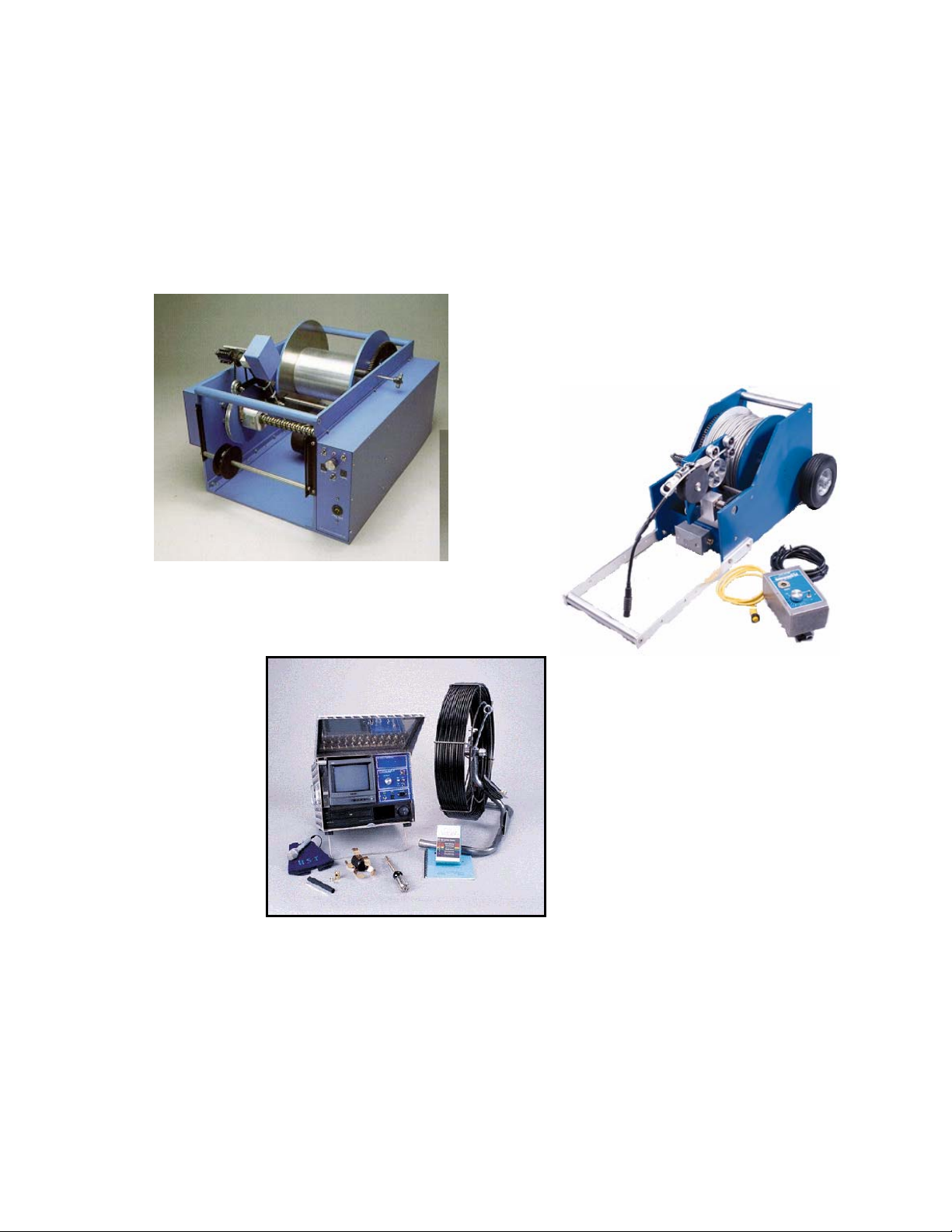
Equipment Compatibility
The R.S. Technical Service Mini Tractor is designed for use with mainline vehicle mounted
systems as well as Portable Mainline systems. This transport requires the use of a power
unit, control box, cable reel and camera.
It may be possible for the RST Mini Tractor to operate with other brands of inspection
equipment. Contact your dealer or RST for possible applications.

Document Number 900-32028 Rev A 7
Accessory Kits for Mini Tractor
The RST Mini Tractor generally comes with the following accessories:
840-30967 KIT, ACCESSORIES, MINI TRACTOR
1701-30543 BOX, TOOL, PLASTIC, W/TRAY 1.0 EA.
2 701-15593 BAG,PLASTIC,2.5 X 3,4 MIL 1000/CS 1.0 EA.
3 316-16857 WASHER,FLT,#6,.438OD,.040T SS 5.0 EA.
4 301-12007 MSCR,PAN,PHH,6-32X.37 SS 5.0 EA.
5 301-11653 MSCR,PAN,PHH,6-32X.25 SS 5.0 EA.
6 560-16073 ADPTR,CBL,10",TNCf > 3PIN MALE PIGTAIL 1.0 EA.
7 867-30925 ASSY, WHEEL ,HEX DRIVE,W/3.5" KNOBBY TIRE, MINI TRACTOR V2 4.0 EA.
8 867-30926 ASSY,CBL,3 PIN MALE(SCREW-ON) - 3 PIN FEM (PUSH-ON) PIGTAIL 1.0 EA.
Document Number 900-32028 Rev A 8
Options
A Dedicated Color Mini Camera
A Dual Purpose Color Mini Camera that can be used with a Push Cable Reel.
Alternative Tire types
Alternative Cable types
Addition bolt on weight.

Document Number 900-32028 Rev A 9
Placement of Inspection Truck
Locate the back of the truck so that the cable reel lines up in the direction of the
pipeline to be inspected.
Allow room to work around the opening while carrying the equipment.
Pull camera/tractor far enough into pipeline to clear the bridle or cable grip.
Check all camera and tractor functions again before proceeding.
Move tractor forward so the rear of the tractor and the cable connections are fully
inside the pipe.
Set up down-hole poles, shoes and manhole roller.
Reset the footage counter.
Release the drag brake on the cable reel.
Set cable reel in the free wheel.
Keep enough room to work around the opening while carrying the equipment.
Placing the equipment into the line
Follow cable grip, bridle and pig tail instructions.
Re-check the pipeline size and extension adjustments.
Do not let cable “loop” at the location where it enters pipeline.
Use guide poles with hook to keep the Mini Tractor stable as it enters pipeline.
Caution: Maintain control of equipment while loading and unloading into
manhole.
Most equipment damage occurs when camera is lowered into hole.
Pull camera/Mini Tractor far enough into pipeline to clear the bridle or cable grip.
Set the cable guide.
Use double roller and/or single rollers, for protecting the cable and allowing it to
slide down the hole without drag on the line.
Use enough poles to clear top of the manhole by 2 feet
Caution: Watch out for people, power lines and traffic when handling the
downhole pole

Document Number 900-32028 Rev A 10
Operation System Power
CAUTION: NEVER HOOK UP OR DISCONNECT ANY EQUIPMENT WITH
POWER TURNED ON!
The Inspection System requires a steady supply of 120VAC to operate properly. Before
starting of the generator or connecting shore power, make sure that ALL equipment inside
the vehicle has been turned OFF. Turn down the controls for camera power and cable reel
speed. After all equipment has been checked, connect the shore power cord.
If a generator is to be used, allow the generator to warm up for a few minutes.
Note: Diesel generators use a different control panel that is separate from the controller
power supply. Refer to the appropriate generator operator’s manual for starting.
Verify that the voltage and frequency indicators on the controller power supply are in the
green zone.
Caution: Before turning on any equipment, plug the keyboard into the
data collection system. Plug the Auxiliary Control Box into the
Auxiliary Control jack on the controller power supply.
Caution: If the voltage or frequency fluctuate into the red zones, DO NOT turn on
any of the equipment in the truck. Check shore power or the generator for proper
operation, or have them checked by a qualified technician.
This manual suits for next models
1
Table of contents
Other RS Technical Services Analytical Instrument manuals


