RSP STC350-SW User manual

Product Manual
Swivel with tool changer STC350-SW
M6624-1
Tool changers | Swivels | Swivels with tool changers | Grippers | Hose packages | Valve Units | Tool systems

2 M6624-1 ver 2.2

M6624-1 ver 2.2 3
The information in this document is subject to change without prior notice and should not be
regarded as an undertaking from Robot System Products AB. Robot System Products AB
assumes no responsibility for errors that may occur in this document.
Robot System Products AB bears no responsibility for damage that is incurred by the use of this
document, or the software or hardware described in this document.
The document, or parts of it, may not be reproduced or copied without prior permission from
Robot System Products AB. It may neither be imparted to a third party, nor otherwise be used
without authorization. Infringement hereof will be subject to action in accordance with the
applicable laws.
Further copies of this document can be obtained from Robot System Products AB at
current prices.
© Robot System Products AB
Robot Systems Products AB
Isolatorvägen 4
SE-721 37 Västerås
Sweden

4 M6624-1 ver 2.2
CONTENTS
1 INTRODUCTION......................................................................................................6
1.1 Safety.........................................................................................................................7
1.1.1 General...............................................................................................................................7
1.1.2 Explanation of warnings .....................................................................................................7
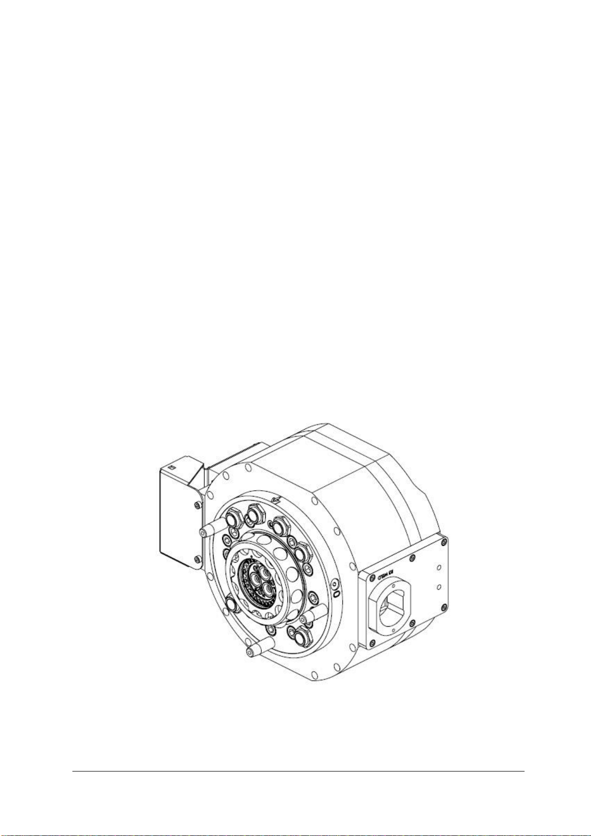
1.2 Description of RSP swivel with tool changer...............................................................8
1.3 Complementary Equipment........................................................................................8
2 TECHNICAL SPECIFICATIONS..............................................................................9
2.1 Description of swivel with tool changers and tool attachments....................................9
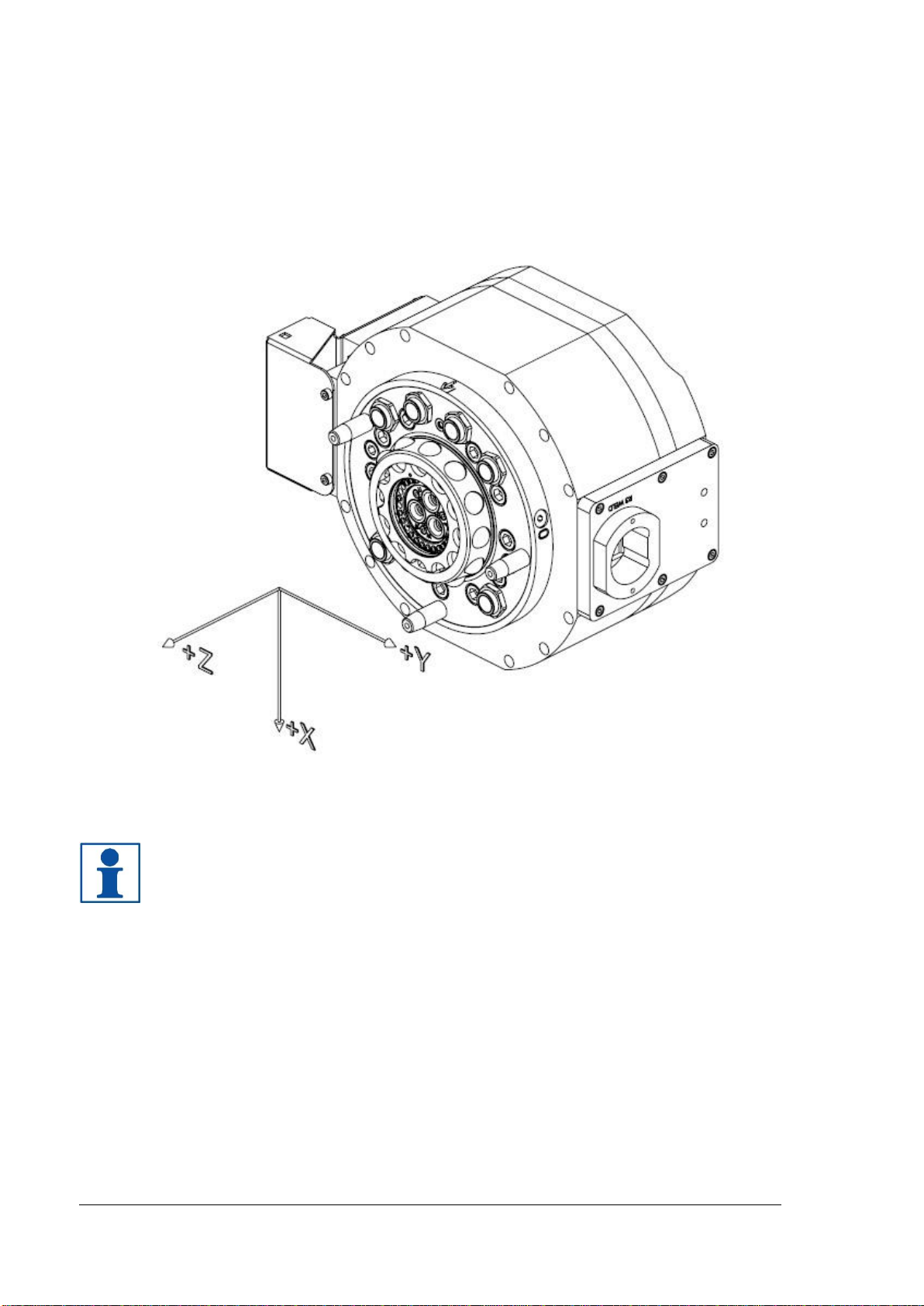
2.1.1 Coordinate System Definition...........................................................................................10
2.1.2 Swivel with tool changer STC350-SWS. Article no: P6621A...........................................11
2.1.3 Swivel with tool changer STC350-SWS with steel shaft. Article no: P6670 ....................13
2.1.4 Tool attachment TA350-SWS, Article no: P6623A...........................................................14
2.1.5 Tool attachment TA350-SWMH, Article no: P6624A .......................................................15
2.1.6 Pneumatic diagram ..........................................................................................................16
2.1.7 E0172-004 for P6621A/P6670 with P6623A....................................................................17
2.1.8 E0172-007 for P6624A.....................................................................................................19
2.2 Options for swivel with tool changer ........................................................................20
2.2.1 Robot adaptation kit/rotation stop ....................................................................................20
2.2.2 Adaptation plates..............................................................................................................20
2.2.3 Manifolder.........................................................................................................................21
2.2.3 Limitation of Robot movements........................................................................................21
2.3 Cooling water ...........................................................................................................22
2.3.1 Water without chemical additives.....................................................................................22
2.3.2 Water with chemical additives..........................................................................................22
2.3.3 Water with alkalinity exceeding pH 8.5 ............................................................................22
2.4 Connection kits and cables.......................................................................................22
3 INSTALLATION.....................................................................................................23
3.1 Tightening torques....................................................................................................23
3.2 Recommended tools for installation..........................................................................23
3.3 Installation of swivel with tool changer on robot........................................................24
3.4 Connect air and water couplings, weld and signal power..........................................26
3.5 Connections on TA350-SWS, P6623A and TA350-SWMH, P6624A........................27
3.6 Installation of tool attachment P6623A/ P6624A on tool ..........................................29
3.7 Manual unlocking of tool changer.............................................................................30
3.8 Hints.........................................................................................................................31

M6624-1 ver 2.2 5
4 MAINTENANCE AND SERVICE...........................................................................32
4.1 Maintenance chart.................................................................................................... 32
4.1.1 Required products............................................................................................................32
4.1.2 Recommended tools for maintenance .............................................................................33
4.1.3 Wear parts........................................................................................................................33
4.1.4 Activities and intervals......................................................................................................33
4.2 Visual inspection...................................................................................................... 34
4.2.1 Inspection of the swivel with tool changer........................................................................34
4.2.2 Inspection of the tool attachment .....................................................................................34
4.3 Cleaning................................................................................................................... 35
4.3.1 Cleaning and lubrication of swivel with tool changer .......................................................35
4.3.2 Cleaning of tool attachment..............................................................................................36
4.4 Replacement of swivel with tool changer.................................................................. 37
4.5 Replacement of wear parts....................................................................................... 38
4.5.1 Replacement of water and air coupling on swivel with tool changer ...............................38
4.5.2 Replacement of signal pins on swivel with tool changer..................................................39
4.5.3 Replacement of contact
pins for weld a
nd servo power on tool attachment.....................40
4.5.4 Replacement of water coupling on tool attachment.........................................................44
4.5.5 Replacement of signal interface ring on tool attachment.................................................45
4.6 Complete service of tool changer............................................................................. 47
5 SPARE PARTS .....................................................................................................48
5.1 Part list for swivel with tool changer, P6621A........................................................... 48
5.2 Part list for swivel with tool changer, P6670 ............................................................. 50
5.2 Part list for tool attachment P6623A......................................................................... 52
5.3 Part list for tool attachment P6624A......................................................................... 53
6 DISPOSAL AND RECYCLING.............................................................................. 54

6 M6624-1 ver 2.2
1 INTRODUCTION
Robot System Products has been the industry leader in high-performance robotic peripheral
products for more than 30 years. Our guiding principle is to provide the highest quality, most
reliable and, in addition, affordable robot tooling products on the market. And, our commitment to
an unparalleled customer service and strong regional retailer partnerships is unmatched.
Robot System Products constantly explores and adopts emerging technologies in order to
develop and market robotic peripherals which combine leading edge design with performance
innovation enabling production 24 hour per day, 7 days a week, all year through. The dedication
to our task has made RSP the most recognized and reputable robot peripheral product brand of
the world.
Robot System Products has a wide range of standard robot peripheral products:
RSP products are available for all major robot brands and come with complete documentation.
3D-models for simulation are available for download at www.rsp.eu.com.
Tool changers
Swivels
Swivels with integrated tool changers
Grippers
Dress Packages
Valve units
Hose packages
Complete function packages
Tool stands

M6624-1 ver 2.2 7
1.1 Safety
1.1.1 General
The integrator installing the tool changer into the system must follow the safety demands stated
in standards and provisions applicable in the country where the tool changer system is to be
installed. The products are all prepared for CE-certification.
The user of the Robot System Products tool changer is responsible that law and directives
applicable in respective countries, with regards to safety, are followed. The user is also
responsible to guarantee that all safety devices are installed correctly.
WARNING!
Never carry out service work on a robot that has not been taken out of operation.
See safety information for the robot.
WARNING!
Only perform work on tools attached to the tool changer if the air pressure is
safely switched off.
WARNING!
Be aware that swivel with tool changer and tool attachment are heavy and may
cause personal injury and equipment damage if dropped.
NOTE!
The tool changer shall always be in locked position, also when empty, to avoid
unexpected locking if air pressure is lost.
WARNING!
Electric signals and power must be disconnected/switched off when docking the
tool attachment. This is to prevent sparking between signal pins and tool
attachment.
1.1.2 Explanation of warnings
The warnings in this document are specific to the products in this manual. It is expected that the
user also pay attention to certain notifications from the robot manufacturer and/or the
manufacturers of other components used in the installation.
WARNING!
The warning sign will make you aware that a situation could result in potential
serious injury or damage to equipment.
NOTE!
The note sign will alert you about something important to consider.

8 M6624-1 ver 2.2
1.2 Description of RSP swivel with tool changer
The RSP swivel with tool changer integrates the advantages of swivels and tool changers into
one single product maximizing the flexibility and productivity of the robot.
Our tool changers enable robots to handle and switch between multiple tools. The patented
locking device TrueConnect™ has a minimum of play and gives an, over the lifespan, absolute
position repeatability. The principle of the TrueConnect™ locking mechanism is that load is
distributed uniformly in all directions through pressing locking balls into spherical grooves in the
tool attachment. In addition this means that substantially larger positional deviations are
accepted when docking. A built-in spring ensures that the tool remains in place in the tool
changer even if the air pressure drops.
Three guide pins align the tool attachment with the tool changer before the electrical connector is
connected, which significantly extends the lifetime for not spring-mounted signal and power pins.
When using a tool changer with integrated swivel compressed air, cooling water, weld power and
electric signals will be directly available at the tool without loose, hanging cables and hoses
which has to be considered during programming. The combination of RSP’s hose packages with
the swivel with integrated tool changer does in addition significantly reduce the design and
installation times for the system integrator.
1.3 Complementary Equipment
Complementary equipment is described in separate documents.
Article
Note
Cable and Hose Packages
Complete packages for most robots on the market
ready to be mounted without any modifications.
Connection kits
In order to make electrical installation easier,
connection kits are available for the tool changer.
3D-models
Available in Solid Works® and STEP-format.

M6624-1 ver 2.2 9
2 TECHNICAL SPECIFICATIONS
2.1 Description of swivel with tool changers and tool attachments
This document presents the swivel with tool changer STC350-SWS and tool attachments. Two
different types of tool attachments are presented:
oSWS for servo weld guns (transfer of air, water, weld and servo power and electric
signals)
oSWMH for grippers (transfer of electric signals, air)
The swivel with tool changer STC350-SWS transfers air, water, weld and servo power and
electric signals to the tool. The unit uses three channels for cooling water (one inlet and two
outlets) and two pneumatic channels. When changing a tool all media channels for water and air
are closed automatically.
The spring loaded signal pins of STC350-SWS are placed and protected along a circle close to
the centre of the tool changer. The contact surfaces for weld and servo power are centrally
placed inside the interface ring with the signal pins. The signal pins are not in connection until at
the very end of the docking cycle when the tool attachment is already properly aligned. This
guarantees a minimum of wear of pins and contact surfaces. The electrical unit can be used for
identification and checking the presence of tools by using signal jumpers and binary coding of
signals on the tool attachment.
Dependent on robot model adaptation plates, for other bolt circles, between the tool changer and
the turning disc on the robot may be needed. Adaptation plates are available from RSP.
STC350-SWS

10 M6624-1 ver 2.2
2.1.1 Coordinate System Definition
A tool changer adds load to the robot. If the arm and tool loads are not stated correctly during
programming the behaviour of the robot and the wear of the equipment will be affected.
Information about weight and centre of gravity can, in accordance with the co-ordinate system
stated below, be found in the technical specification tables of the swivel with tool changers.
NOTE!
For the swivel with tool changer origo is situated on the surface in the centre of
the robot mounting flange.

M6624-1 ver 2.2 11
2.1.2 Swivel with tool changer STC350-SWS. Article no: P6621A
Tool changer STC350-SWS transfers 2 pneumatic channels, 3 water channels, 23 electric
signals, 3 servo power signals and 3 weld power signals to the tool attachment.

12 M6624-1 ver 2.2
Technical data
Working temperature
+10°C - +60°C
Bolt pattern
ISO 9409-1-160-11-M12
Maximum tool load
Fz
Mx/My
Mz
± 3500 N
± 2300 Nm
± 2300 Nm
Weight and centre of gravity
29.9 kg
0.2 / -2.5 / 103.5 mm
39.1 kg
0.3 / -1.5 / 129.4 mm
38.9 kg
1.6 / -2.3 / 128.2 mm
P6621A
P6621A+P6623A
P6621A+P6624A
Weight
Mass centre X / Y / Z
Weight
Mass centre X / Y / Z
Weight
Mass centre X / Y / Z
Air/water channels
Pneumatic diagram
Number of ducts
Dedicated air ducts
Dedicated water ducts
Max air/water pressure
Air flow
Water flow
Connection, robot side
Air quality
Water quality
See section 2.1.6
5 totally
1 for regulated air (0-10 bar)
1 for unregulated air (6-10 bar)
1 for inlet water (0-10 bar)
2 for return water (0-10 bar)
10 bar
2000 l/min
16 l/min
Manifolder A0172-065
Oil-clean and waterless filtered air, with max
25µm particle content
See section 2.3.1 and 2.3.2
Signal and servo
power channels
Number of signals
Dedicated signals
Max current
Max voltage
Number of servo channels
Max current (servo)
Max voltage (servo)
Connection, robot side
27 totally
1 x 24 V
1 x 0 V
Open TC (+24V)
Close TC (+24V)
TC Opened (+24V)
TC Closed (+24V)
2 A
60 V
3 totally
15A
690V
3-module Harting 10B
Weld power signals
Number of weld power
channels
Max current
Max continuous current
Max voltage
Connection, robot side
3 totally
400A max for 0.6s
135A
690V
MC TSS150

M6624-1 ver 2.2 13
2.1.3 Swivel with tool changer STC350-SWS with steel shaft. Article no:
P6670
Tool changer STC350-SWS transfers 2 pneumatic channels, 3 water channels, 23 electric
signals, 3 servo power signals and 3 weld power signals to the tool attachment. P6670 is an
equivalent alternative to P6621A except for a steel shaft instead of aluminium for preventing
corrosion when alkalinity is exceeding pH 8.5.
Technical data
Working temperature
+10°C - +60°C
Bolt pattern
ISO 9409-1-160-11-M12
Maximum tool load
Fz
Mx/My
Mz
± 3500 N
± 2300 Nm
± 2300 Nm
Air/water channels
Water quality
See section 2.3.3
Weight and centre of gravity
34.7 kg
0.6 / -2.0 / 106.4 mm
44.0 kg
0.6 / -1.5 / 128.9 mm
43.4 kg
0.9 / -2.0 / 127.9 mm
P6670
P6670+P6623A
P6670+P6624A
Weight
Mass centre X / Y / Z
Weight
Mass centre X / Y / Z
Weight
Mass centre X / Y / Z

14 M6624-1 ver 2.2
2.1.4 Tool attachment TA350-SWS, Article no: P6623A
Technical data
Working temperature
+10°C - +60°C
Bolt pattern
ISO 9409-1-160-11-M12
Weight
9.3 kg
Maximum tool load
(M12-screws)
Mx/My
Mz
±2300 Nm
±2300 Nm
Maximum tool load
(M10-screws)
Mx/My
Mz
±1250 Nm
±1250 Nm
Air/water channels
Number of air ducts
Number of water ducts
Connections, tool side
2 totally
3 totally
G 1/2"
Signal and servo
power channels
Number of signals
Number of servo channels
Connection, tool side
22 totally
3 totally
3 x 19S Souriau
Weld power signals
Number of power channels
Connections, tool side
3 totally
1.5m 3x 25mm2cable, open end
Note! Tools can be mounted to the tool attachment using six M12-screws,
alternatively the tool attachment can be mounted to the tool using six M10-screws.

M6624-1 ver 2.2 15
2.1.5 Tool attachment TA350-SWMH, Article no: P6624A
Technical data
Working temperature
+10°C - +60°C
Bolt pattern
ISO 9409-1-160-11-M12
Weight
8.7 kg
Maximum tool load
(M12-screws)
Mx/My
Mz
±2300 Nm
±2300 Nm
Maximum tool load
(M10-screws)
Mx/My
Mz
±1250 Nm
±1250 Nm
Air/water channels
Number of air ducts
Connections, tool side
1 totally
G 1/2"
Signal channels
Number of signals
Connections, tool side
11 totally
19S Souriau
Note! Tools can be mounted to the tool attachment using six M12-screws,
alternatively the tool attachment can be mounted to the tool using six M10-screws.

16 M6624-1 ver 2.2
2.1.6 Pneumatic diagram

M6624-1 ver 2.2 17
2.1.7 E0172-004 for P6621A/P6670 with P6623A

18 M6624-1 ver 2.2

M6624-1 ver 2.2 19
2.1.8 E0172-007 for P6624A

20 M6624-1 ver 2.2
2.2 Options for swivel with tool changer
2.2.1 Robot adaptation kit/rotation stop
An adaptation kit/rotation stop is mandatory and prohibits the swivel with tool changer to rotate in
relation to the robot. Dependent on robot model alternative rotation stops are required, which are
available from RSP.
2.2.2 Adaptation plates
The flange of the swivel with tool changer has fastening holes in accordance with ISO 9409-1
according to the figure below. Dependent on robot model adaptation plates, for other bolt circles,
between the tool changer and the turning disc on the robot may be needed. Adaptation plates
are available from RSP.
Table of contents
Other RSP Industrial Equipment manuals

RSP
RSP TC350 Series User manual

RSP
RSP S20 Instruction Manual

RSP
RSP Compact Series Instruction Manual

RSP
RSP TC60 Instruction Manual

RSP
RSP TC20 User manual

RSP
RSP STC20 Instruction Manual

RSP
RSP TC250-8 User manual

RSP
RSP TPS400 User manual

RSP
RSP Moduflex Series Instruction Manual

RSP
RSP STC20 User manual
Popular Industrial Equipment manuals by other brands

Toray
Toray NHP210 Series instruction manual

SCHUNK
SCHUNK ROTA THW3 Translation of original operating manual

Dynamics
Dynamics Dings 70 Series instructions

Siemens
Siemens ULTRAMAT 6 Series Compact operating instructions

Tektronix
Tektronix IntelliFrame VX1410A instruction manual

ABB
ABB HT576242 Operation manual