RSP TC5 User manual

m0403
Product Manual
Tool changer TC5
M0109-1
Tool changers | Swivels | Swivel tool changers | Grippers | Hose packages | Valve units | Tool systems

2 M0109-1 ver 2.2

M0109-1 ver 2.2 3
The information in this document is subject to change without prior notice and should not be
regarded as an undertaking from Robot System Products AB. Robot System Products AB
assumes no responsibility for errors that may occur in this document.
Robot System Products AB bears no responsibility for damage that is incurred by the use of this
document, or the software or hardware described in this document.
The document, or parts of it, may not be reproduced or copied without prior permission from
Robot System Products AB. It may neither be imparted to a third party, nor otherwise be used
without authorization. Infringement hereof will be subject to action in accordance with the
applicable laws.
Further copies of this document can be obtained from Robot System Products AB at
current prices.
© Robot System Products AB
Robot Systems Products AB
Isolatorvägen 4
SE-721 37 Västerås
Sweden

4 M0109-1 ver 2.2
CONTENTS
1 INTRODUCTION......................................................................................................6
1.1 Safety.........................................................................................................................7
1.1.1 General...............................................................................................................................7
1.1.2 Explanation of warnings .....................................................................................................7
1.2 Description of RSP tool changers...............................................................................8
1.3 Complementary Equipment........................................................................................8
2 TECHNICAL SPECIFICATIONS..............................................................................9
2.1 Description of tool changers and tool attachments .....................................................9
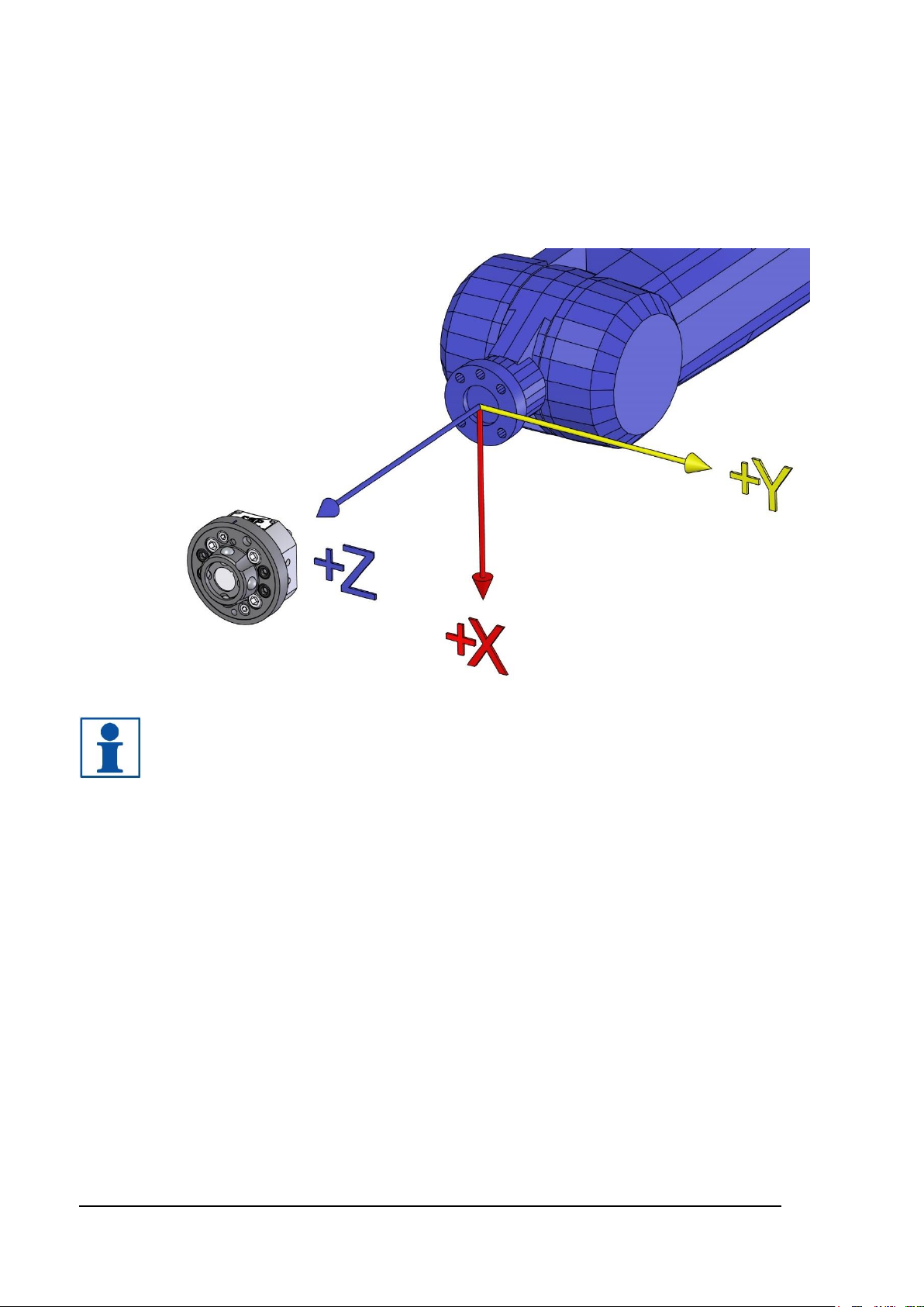
2.1.1 Coordinate System Definition...........................................................................................10
2.1.2 Tool changer with air, TC5-6. Article no: P1001 ..............................................................11
2.1.3 Tool attachment TA5-6, Article no: P1002.......................................................................12
2.1.4 Tool changer with air and electric signals, TC5-4E. Article no: P1003............................13
2.1.5 Tool attachment TA5-6, Article no: P1004.......................................................................14
2.1.6 Pneumatic diagram for TC5 and TA5...............................................................................15
2.1.7 Circuit diagram E0211-006 for P1003..............................................................................16
2.1.8 Circuit diagram E0211-007 for P1004..............................................................................17
2.2 Options to tool changers and tool attachment...........................................................18
2.2.1 Signal interface, 8 signals, robot side. Article no: P1013.................................................18
2.2.2 Signal interface, 8 signals, tool side. Article no: P1014 ...................................................19
2.2.3 Tool stand kit. Article no: P1005.......................................................................................20
2.2.4 Robot adaptation kit .........................................................................................................20
2.2.5 Limitation of Robot movement..........................................................................................21
2.2.6 Connection kits and cables ..............................................................................................21
3 INSTALLATION.....................................................................................................21
3.1 Tightening torques....................................................................................................21
3.2 Recommended tools for installation..........................................................................21
3.3 Installation of tool changer on robot..........................................................................22
3.4 Installation of tool attachment to gripper/tool ............................................................23
3.5 Hints.........................................................................................................................24
3.5.1 Programming....................................................................................................................24
3.5.2 Sparking ...........................................................................................................................24
3.5.3 Electrical installation.........................................................................................................24
3.5.4 Tool stand.........................................................................................................................24
3.5.5 Tool Identification .............................................................................................................24

M0109-1 ver 2.2 5
4 MAINTENANCE AND SERVICE...........................................................................25
4.1 Maintenance chart.................................................................................................... 25
4.1.1 Required products............................................................................................................25
4.1.2 Recommended tools for maintenance .............................................................................26
4.1.3 Wear parts........................................................................................................................26
4.1.4 Activities and intervals on tool changer............................................................................26
4.1.5 Activities and intervals on tool attachment.......................................................................27
4.2 Visual inspection...................................................................................................... 27
4.2.1 Inspection of the tool changer..........................................................................................27
4.2.2 Inspection of the tool attachment .....................................................................................27
4.3 Cleaning................................................................................................................... 28
4.3.1 Cleaning and lubrication of swivel with tool changer .......................................................28
4.3.2 Cleaning of tool attachment..............................................................................................29
4.4 Replacement of wear parts....................................................................................... 30
4.4.1 Replacement of air sealings.............................................................................................30
4.4.2 Replacement of signal pins (TC5-4E only).......................................................................30
4.5 Complete service of tool changer............................................................................. 31
4.6 Replacement of tool changer.................................................................................... 31
5 SPARE PARTS .....................................................................................................33
5.1 Part list for tool changer P1001 and P1003.............................................................. 33
5.2 Part list for tool attachment P1002 and P1004.......................................................... 33
5.3 Part list for signal interface P1013............................................................................ 34
5.4 Part list for signal interface P1014............................................................................ 34
6 DISPOSAL AND RECYCLING.............................................................................. 35

6 M0109-1 ver 2.2
1 INTRODUCTION
Robot System Products is a front-rank provider of peripheral products for high performance
robot applications. We provide complete system solutions for your robot installations, aiming to
improve your productivity with the most reliable and cost-effective tooling on the market.
Continuously we explore emerging technologies, working with leading edge design.
Robot System Products has a wide range of standard robot peripheral products:
•Tool changers
•Swivels
•Swivels with integrated tool changers
•Grippers
•Hose Packages
•Valve units
•Tool systems
•Tool stands
Robot System Products’ tool changers are constructed to maximize the flexibility and reliability
of your robot fleet. Through our patented locking device TrueConnect™ robustness and high
safety are combined with low weight and compactness. With our swivels you can provide
compressed air, water, electrical and data signals as well as weld and servo power to your tools
with robot motion capabilities fully maintained. Our swivels with tool changers unites the
TrueConnect™ tool changing mechanism with our swivel technology, combining the best out of
two technologies.
Robot System Products’ product lines are available for all major robot brands and come with
complete documentation. 3D-models for simulation are available for download at:
www.rsp.eu.com

M0109-1 ver 2.2 7
1.1 Safety
1.1.1 General
The integrator installing the tool changer into the system must follow the safety demands stated
in standards and provisions applicable in the country where the tool changer system is to be
installed. The products are all prepared for CE-certification.
The user of the Robot System Products tool changer is responsible that law and directives
applicable in respective countries, with regards to safety, are followed. The user is also
responsible to guarantee that all safety devices are installed correctly.
WARNING!
Never carry out service work on a robot that has not been taken out of operation.
See safety information for the robot.
WARNING!
Only perform work on grippers or tools attached to the tool changer if the air
pressure is safely switched off.
WARNING!
Be aware that tool changer and tool attachment may cause personal injury and
equipment damage if dropped.
NOTE!
The tool changer shall always be in locked position, also when empty, to avoid
unexpected locking if air pressure is lost.
WARNING!
Electric signals and power must be disconnected/switched off when docking the
tool attachment. This is to prevent sparking between signal pins and tool
attachment.
1.1.2 Explanation of warnings
The warnings in this document are specific to the products in this manual. It is expected that the
user also pay attention to certain notifications from the robot manufacturer and/or the
manufacturers of other components used in the installation.
WARNING!
The warning sign will make you aware that a situation could result in potential
serious injury or damage to equipment.
NOTE!
The note sign will alert you about something important to consider.

8 M0109-1 ver 2.2
1.2 Description of RSP tool changers
Our tool changers enable robots to handle and switch between multiple tools. They are built to
ensure reliable and smooth operation, being compact with low weight and robust design and
incorporating many safety features. Depending on model and options, electrical signals, weld
and servo power, data, water and compressed air are transferred from the robot side to the tool.
The patented locking device TrueConnect™ has a minimum of play and gives a practically,
through the lifespan, absolute positioning repeatability. The principle behind the locking
mechanism is the uniform distribution of load obtained by pressing looking balls into spherical
grooves. In consequence, substantially larger positional tolerances are accepted during docking.
1.3 Complementary Equipment
Complementary equipment is described in separate documents.
Article
Note
Cable and Hose Package
Complete packages for most robots on the market ready to be
mounted without any modifications.
Tool Stands
Tool stands will, combined with tool attachments and
adaptation kits, give a rigid installation for easy tool changing.
Connection kits
In order to make electrical installation easier, connection kits
are available for tool changers and tool attachments.
3D-models
Available in Solid Works® and STEP-format.

M0109-1 ver 2.2 9
2 TECHNICAL SPECIFICATIONS
2.1 Description of tool changers and tool attachments
This document presents the Robot System Products TC5-6 and TC5-4E tool changers including
tool attachments dedicated for material handling. Likewise presented are adaptation kits,
connection kits to facilitate electrical installation and a tool stand kit.
The tool changer TC5-6 transfers compressed air to the tool. It can be equipped with transfer of
electrical signals, via spring loaded signal pins, to the tool attachment. The electrical version is
designated ’E’. The tool changers TC5-6 and TC5-4E cannot transport fluids.
For other bolt circles adaptation plates between the tool changer and the turning disc on the
robot may be needed. Such adaptation plates are available from RSP.
TC5-6

10 M0109-1 ver 2.2
2.1.1 Coordinate System Definition
A tool changer adds load to the robot. If the arm and tool loads are not stated correctly during
programming the behaviour of the robot and the wear of the equipment will be affected.
Information about weight and centre of gravity can, in accordance with the co-ordinate system
stated below, be found in the technical specification tables of the tool changer.
NOTE!
For the tool changer and tool changer with tool attachment, the origo is situated in
the centre of the robot mounting flange.

M0109-1 ver 2.2 11
2.1.2 Tool changer with air, TC5-6. Article no: P1001
Tool changer TC5-6 transfers 6 pneumatic channels to the tool attachment. To be used
together with tool attachment P1003.
Technical data
Working temperature
+10°C−+60°C
Bolt pattern
ISO 9409-1 31.5-4-M5
Maximum tool load
Fz (static)
Mx/My (dynamic)
Mz (dynamic)
±50 N
±50 Nm
±50 Nm
Weight and centre of gravity
P1001
P1001+P1002
Weight
Mass centre X / Y / Z
Weight
Mass centre X / Y / Z
0.23 kg
0.0 / 16.2 / 0.4 mm
0,28 kg
0.0 /19.1 / 0.2 mm
Air ducts
Pneumatic diagram
Total number of ducts
Dedicated air ducts
Max air pressure
Air flow
Connection, robot side
Air quality
See section 2.1.6
8
Open TC marked O (6−10 bar)
Close TC marked C (6−10 bar)
10 bar
100 l/min
M5
Oil-clean and waterless filtered air, with max
25µm particle content

12 M0109-1 ver 2.2
2.1.3 Tool attachment TA5-6, Article no: P1002
Tool attachment TA5-6 transfers 6 pneumatic channels to the tool. To be used together with
tool changer P1001.
Technical data
Working temperature
+10°C−+60°C
Bolt pattern
ISO 9409-1 31.5-4-M5
Weight
0.06 kg
Maximum tool load
M6-screws)
Fz (static)
Mx/My (dynamic)
Mz (dynamic)
±50 N
±50 Nm
±50 Nm
Maximum tool load
(M5-screws)
Fz (static)
Mx/My (dynamic)
Mz (dynamic)
±50 N
±50 Nm
±30 Nm
Air ducts
Number of ducts
Connection, tool side
6
M5
NOTE! Tools can be mounted to the tool attachment using four M5-screws,
alternatively the tool attachment can be mounted to the tool using four M4-screws

M0109-1 ver 2.2 13
2.1.4 Tool changer with air and electric signals, TC5-4E. Article no: P1003
Tool changer TC5-6 transfers 6 pneumatic channels to the tool attachment. To be used
together with tool attachment P1004.
Technical data
Working temperature
+10°C−+60°C
Bolt pattern
ISO 9409-1 31.5-4-M5
Maximum tool load
Fz (static)
Mx/My (dynamic)
Mz (dynamic)
±50 N
±50 Nm
±50 Nm
Weight and centre of gravity
P1003
P1001+P1003
Weight
Mass centre X / Y / Z
Weight
Mass centre X / Y / Z
0.26 kg
0.3 / 4.1 / 15.6 mm
0,34 kg
0.2 / 5.8 / 19.0 mm
Air ducts
Pneumatic diagram
Total number of ducts
Dedicated air ducts
Max air pressure
Air flow
Connection, robot side
Air quality
See section 2.1.6
6
Open TC marked O (6−10 bar)
Close TC marked C (6−10 bar)
10 bar
100 l/min
M5
Oil-clean and waterless filtered air, with max
25µm particle content
Electrical signals
Circuit diagram
Total number of signals
Dedicated signals
Max current
Max voltage
Connections
E0211-006 (see section 2.1.7)
8
−
1 A
60 V
M12 8p

14 M0109-1 ver 2.2
2.1.5 Tool attachment TA5-4E, Article no: P1004
Tool attachment TA20-4 transfers 6 pneumatic channels to the tool. To be used together with
tool changer P1003.
Technical data
Working temperature
+10°C−+60°C
Bolt pattern
ISO 9409-1 31.5-4-M5
Weight
0.08 kg
Maximum tool load
M6-screws)
Fz (static)
Mx/My (dynamic)
Mz (dynamic)
±50 N
±50 Nm
±50 Nm
Maximum tool load
(M5-screws)
Fz (static)
Mx/My (dynamic)
Mz (dynamic)
±50 N
±50 Nm
±30 Nm
Air ducts
Number of ducts
Connection, tool side
4
M5
Electrical signals
Circuit diagram
Total number of signals
Connection, tool side
E0211-007 (see section 2.1.8)
8
0.8 m cable (8x0.25 mm²) with free end
NOTE! Tools can be mounted to the tool attachment using four M6-screws,
alternatively the tool attachment can be mounted to the tool using four M5-screws.

M0109-1 ver 2.2 15
2.1.6 Pneumatic diagram for TC5 and TA5
NOTE!
Ducts 1 and 2 are not available for TC5-4E and TA5-4E!

16 M0109-1 ver 2.2
2.1.7 Circuit diagram E0211-006 for P1003

M0109-1 ver 2.2 17
2.1.8 Circuit diagram E0211-007 for P1004

18 M0109-1 ver 2.2
2.2 Options to tool changers and tool attachment
2.2.1 Signal interface, 8 signals, robot side. Article no: P1013
Transfers 8 electrical signal to the tool attachment. Can be mounted at two different positions on
the tool changer.
To be used with option P1014 on the tool attachment.
Technical data
Weight
0.04 kg
Electrical signals
Circuit diagram
Total number of signals
Dedicated signals
Max current
Max voltage
Connections
E0211-006 (see section 2.1.7)
8
−
1 A
60 V
M12 8p
NOTE! P1013 is included in P1003. An additional P1013 can be mounted on
P1003, making totally 16 electrical signals transferable but limiting the pneumatic
channels to 4 including Open TC and Close TC.

M0109-1 ver 2.2 19
2.2.2 Signal interface, 8 signals, tool side. Article no: P1014
Transfers 8 electrical signal to the tool. Can be mounted at two different positions on the tool
attachment.
To be used with option P1013 on the tool changer.
Technical data
Weight
0.02 kg
Electrical signals
Circuit diagram
Total number of signals
Connection, tool side
E0211-007 (see section 2.1.8)
8
0.8 m cable (8 x 0.25 mm²) with free end
NOTE! P1014 is included in P1004. An additional P1014 can be mounted on
P1004.

20 M0109-1 ver 2.2
2.2.3 Tool stand kit. Article no: P1005
This tool stand kit gives, when the brackets are mounted on a stand, a robust tool stand for easy
tool changing.
NOTE! The four enclosed screws and spacers shall be mounted on the tool
attachments P1002 or P1004.
Technical data
Weight
0.02 kg
Maximum load
5 kg
2.2.4 Robot adaptation kit
The flange of TC5 has fastening holes in accordance with ISO 9409-1-40-4-M6.
Adaptation plates, which are mounted between the tool changer and the robot flange, are
available for other bolt circles. The order number is customer specific, depending on the robot.
Other manuals for TC5
1
This manual suits for next models
8
Table of contents
Other RSP Industrial Equipment manuals

RSP
RSP STC350-SW User manual

RSP
RSP TC250-8 User manual

RSP
RSP TPS400 User manual

RSP
RSP STC20 Instruction Manual

RSP
RSP TC350 Series User manual

RSP
RSP TC20 User manual

RSP
RSP S20 Instruction Manual

RSP
RSP Moduflex Series Instruction Manual

RSP
RSP Compact Series Instruction Manual

RSP
RSP TC60 Instruction Manual
Popular Industrial Equipment manuals by other brands

Ripley
Ripley Miller 400 Series operating instructions

MCCOY
MCCOY FARR CANADA HD31000 Tong Technical manual

Simplex
Simplex VSH SUPER Technical information installation instructions

Festo
Festo ELGA-BS-KF-70 Repair instructions

turck
turck BC10-P30SR-VP4X2/3GD operating instructions

Innova
Innova PantoVision T2 USER INTERFACE MANUAL