RSP TC60 Instruction Manual

Installation and Maintenance
Manual
Tool changers TC60, TC120, TC180
M0627-1
Tool changers | Swivels | Swivels with Tool changers | Grippers | Hose packages | Valve Units | Tool systems

2 M0627-1 version 3.3

M0627-1 version 3.3 3
The information in this document is subject to change without prior notice and should not be
regarded as an undertaking from Robot System Products AB. Robot System Products AB
assumes no responsibility for errors that may occur in this document.
Robot System Products AB bears no responsibility for damage that is incurred by the use of this
document, or the software or hardware described in this document.
The document, or parts of it, may not be reproduced or copied without prior permission from
Robot System Products AB. It may neither be imparted to a third party, nor otherwise be used
without authorization. Infringement hereof will be subject to action in accordance with the
applicable laws.
Further copies of this document can be obtained from Robot System Products AB at
current prices.
© Robot System Products AB
Robot Systems Products AB
Isolatorvägen 4
SE–721 37 Västerås
Sweden

4 M0627-1 version 3.3
CONTENTS
1 INTRODUCTION......................................................................................................5
1.1 Installation and Maintenance manual .........................................................................5
1.2 Safety.........................................................................................................................6
1.2.1 General...............................................................................................................................6
1.2.2 Explanation of warnings .....................................................................................................6
1.3 Tightening torques......................................................................................................7
1.4 Recommended equipment .........................................................................................7
1.5 Required products......................................................................................................7
2 INSTALLATION.......................................................................................................8
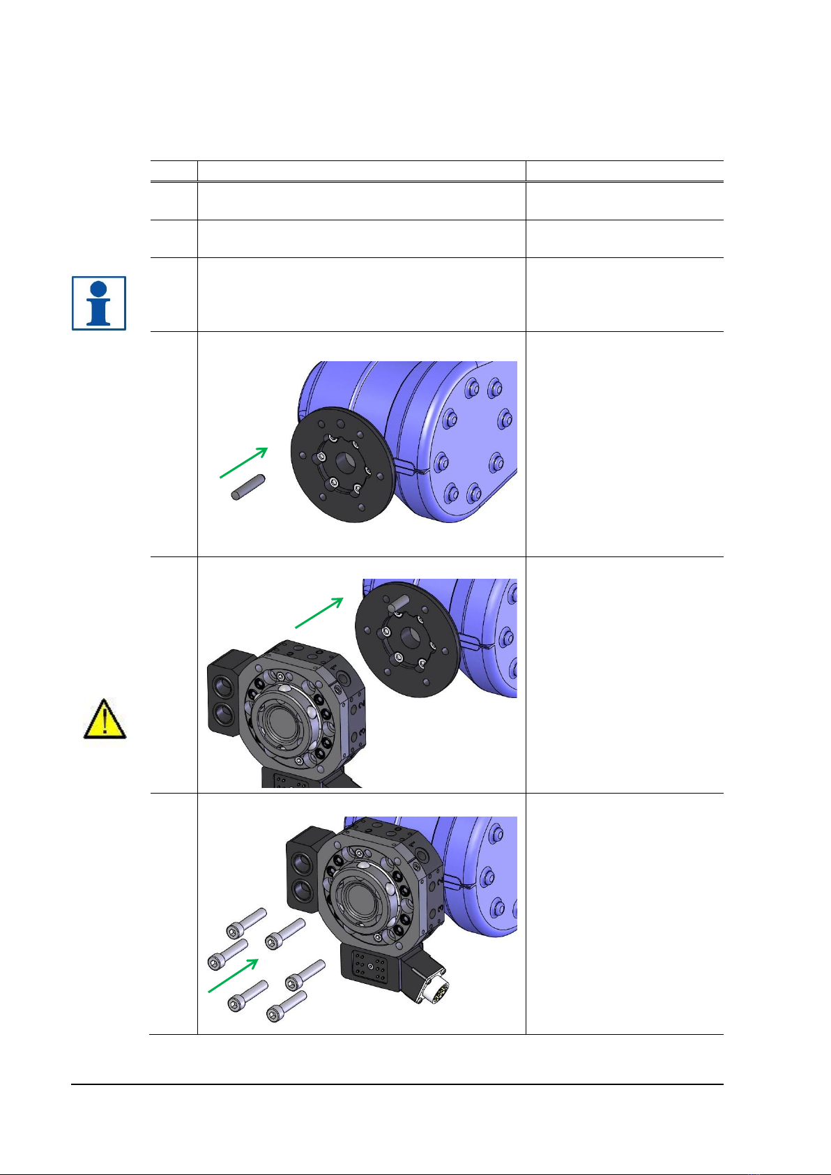
2.1 Installation of tool changer on robot............................................................................8
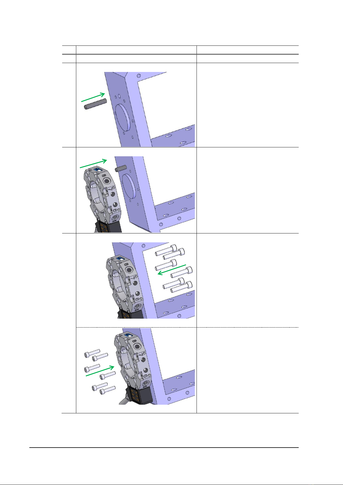
2.2 Installation of tool attachment to tool ........................................................................10
2.3 Mounting of parking bracket plate.............................................................................11
2.4 Mounting of parking bracket kit.................................................................................12
3 MAINTENANCE AND SERVICE............................................................................13
3.1 Maintenance scheme ...............................................................................................13
3.1.1 Every second week ..........................................................................................................13
3.1.2 Every six-months or 250,000 tool changes......................................................................14
3.1.3 To replace when damaged or worn-out ...........................................................................14
3.2 Specification of maintenance activities.....................................................................15
3.2.1 Visual inspection of tool changer (every 2nd week).........................................................15
3.2.2 Visual inspection and cleaning of tool attachment (every 2nd week) ..............................16
3.2.3 Cleaning and lubrication of TC (every 6th month or 250,000 tool changes).....................18
3.2.4 Cleaning and lubrication of TA (every 6th month or 250,000 tool changes)....................21
4 DISMOUNTING AND REPLACEMENT.................................................................22
4.1 Replacement of tool changer....................................................................................22
4.2 Replacement of tool attachment...............................................................................24
4.3 Replacement of wear parts.......................................................................................26
4.3.1 Replacement of air sealings on TC180............................................................................26
4.3.2 Replacement of air sealings on TC60, TC120 and air module, TC-side..........................27
4.3.3 Replacement of guide pins (P1314) on tool changers.....................................................28
4.3.4 Replacement of spring-loaded signal pins on signal interface, TC-side..........................29
4.3.5 Replacement of signal, servo power, high voltage interface and air module, TC-side....30
4.3.6 Replacement of signal interface/air module, TA-side ......................................................31
4.3.7 Replacement of O-rings on signal interface, TA-side ......................................................32
5 DISPOSAL AND RECYCLING ..............................................................................33

M0627-1 version 3.3 5
1 INTRODUCTION
Robot System Products is a front-rank provider of peripheral products for high performance
robot applications. We provide complete tool systems solutions for your robot installations,
aiming to improve your productivity with the most reliable and cost-effective tooling on the
market. Continuously we explore emerging technologies, working with leading edge design.
Robot System Products has a wide range of standard robot peripheral products:
•Tool changers
•Swivels
•Swivel tool changers
•Circular Rotators
•Grippers
•Hose Packages
•Valve units
•Tool systems
•Tool stands
Robot System Products’ tool changers are constructed to maximize the flexibility and reliability
of your robot fleet. Through our patented locking device TrueConnect™ robustness and high
safety are combined with low weight and compactness. With our swivels compressed air, water,
electrical and data signals as well as weld and servo power are transferred to your tools with
robot motion capabilities fully maintained. Our Swivel tool changers unite the TrueConnect™
mechanism with our swivel technology, combining the best out of the two technologies. With
RSPs unique Circular Rotators cables and hoses can be freely selected with high robot flexibility
maintained, and the space requirements reduced. Our integrated Tool systems are delivered as
complete plug-and-play solutions designed for quick and simple installation.
Robot System Products’product lines are available for all major robot brands and come with
complete documentation. 3D-models for simulation are available for download at:
www.rsp.eu.com
1.1 Installation and Maintenance manual
This document describes how the tools changers, TC60, TC120 and TC180, including
corresponding tool attachments and options for transfer of power, signals, water and air are
installed and replaced. In addition, the document describes required maintenance activities,
including inspection, cleaning, lubrication, replacement of wear parts, required tools and
products and disposal and recycling.
The document, Product Description (M0626-1) contains product information, drawings, technical
data, electrical and pneumatic diagrams, safety software function and lists of spare parts.

6 M0627-1 version 3.3
1.2 Safety
1.2.1 General
The integrator installing the tool changer into the system must follow the safety demands stated
in standards and provisions applicable in the country where the tool changer system is to be
installed. The products are all prepared for CE-certification.
The user of the Robot System Products tool changer is responsible that law and directives
applicable in respective countries, with regards to safety, are followed. The user is also
responsible to guarantee that all safety devices are installed correctly.
WARNING!
Never carry out service work on a robot that has not been taken out of operation.
See safety information for the robot.
WARNING!
Only perform work on grippers or tools attached to the tool changer if the air
pressure is safely switched off.
WARNING!
Be aware that tool changer and tool attachment are heavy and may cause personal
injury and equipment damage if dropped.
NOTE!
The tool changer shall always be in locked position, also when empty, to avoid
unexpected locking if air pressure is lost.
1.2.2 Explanation of warnings
The warnings in this document are specific to the products in this manual. It is expected that the
user also pay attention to certain notifications from the robot manufacturer and/or the
manufacturers of other components used in the installation.
WARNING!
The warning sign will make you aware that a situation could result in potential
serious injury or damage to equipment.
NOTE!
The note sign will alert you about something important to consider.

M0627-1 version 3.3 7
1.3 Tightening torques
Tightening torques for mounting (screw class 8.8)
Dimension
Torque
M4
3 Nm
M5
6 Nm
M6
10 Nm
M8
24 Nm
M10
47 Nm
M12
82 Nm
M16
200 Nm
1.4 Recommended equipment
Equipment recommended for installation and maintenance work
Tools
Applications
Complete set of Allen keys
For all socket head cap screws
Torque wrench
For dismounting and mounting
Torx keys
For dismounting and mounting
Plastic mallet
For mounting of air sealings
Pair of pliers
For dismounting the signal pins
Guide pin puller (VA0182-001)
For dismounting the guide pins
2 x 13 mm spanners
For dismounting the guide pins
Screw driver
For removing the air sealings
1.5 Required products
Product
Specification
Note
Grease, 3HXG1000-413
Magnalube-G, Teflon grease
Air sealings.
Grease I0876
Molykote BR2Plus
For guide pins, guide holes and
locking balls.
Cleaning agent
Industrial alcohol or similar
For cleaning of tool changer and tool
attachment.
Glue
Loctite 6300 (or similar)
For gluing the guide pins.
Glue
Loctite 480 (or similar)
For gluing air sealings (TC60, TC120
and option two air, P1325).
Cloth
Lint free cloth
For cleaning.
NOTE! Chemical resistance protective gloves are recommended when using grease
or cleaning agents such as industrial alcohol. Safety goggles are recommended
when working with cleaning agents such as industrial alcohol. Adequate ventilation
should be provided when chemical substances are used.

8 M0627-1 version 3.3
2 INSTALLATION
2.1 Installation of tool changer on robot
Action
Note
1
Safety
Read the safety section
(1.2).
2
Service position
Place the robot in service
position
3
Power off
Switch the power off and
lock the circuit breaker
NOTE! Read the safety
chapter for the robot.
4
Mount guide pin
Press the enclosed guide
pin into the robot flange.
Alternatively, if adaptation
plate is used:
Mount the adaptation plate
on the robot flange (see
tightening torques above).
Press the enclosed guide
pin into the adaptation
plate.
5
Fit tool changer
Lift and the tool changer to
the robot flange (or
adaptation plate). Make
sure that the guide pin is
fitted to the guide hole in
the tool changer.
WARNING! The tool
changer is heavy and may
cause personal injury and
equipment damage if
dropped.
6
Mount tool changer
Mount the tool changer with
the enclosed screws. Use
an Allen key for tightening
(see tightening torques
above).

M0627-1 version 3.3 9
7
Connect air hoses
Connect air hoses to the
hose fittings.
Pneumatic diagrams are
found in the Product
Description of respective
unit.
8
Connect signals
Connect electrical
connectors in accordance
with selected options.
Circuit diagrams are found
in the Product Description
of respective unit.
9
Power on
Unlock circuit breaker and
switch power on.

10 M0627-1 version 3.3
2.2 Installation of tool attachment to tool
Action
Note
1
Safety
Read the safety section (1.2).
2
Mount guide pin
Press, when required, a guide pin
(CPK 8x) into its position on the
tool.
3
Fit tool attachment
Lift the tool attachment to the tool
and fit using the guide pin, if
applicable, into its appropriate guide
hole.
4
Mount tool attachment on tool
M6/M8
Mount tool attachment from the tool
side using a torque wrench.
Screws are specified in the Product
Description of respective tool
attachment. See tightening torques
above.
M8/M10
Alternatively: mount tool from the
tool attachment side using a torque
wrench.
Screws are specified in the Product
Description of respective tool
attachment. See tightening torques
above.

M0627-1 version 3.3 11
5
Connect air hoses
Connect air hoses to the hose
fittings on the tool attachment or
selected option.
Pneumatic diagrams are found in
the Product Description of
respective unit.
6
Connect signals
Connect electrical connectors in
accordance with selected options.
Circuit diagrams are found in the
Product Description of respective
unit.
2.3 Mounting of parking bracket plate
1
Safety
Read the safety section (1.2).
2
Fit and mount parking bracket plate
Fit the parking bracket plate
(P1331, P1405 or P1805) to the tool
attachment, using the guide pin,
and mount with the two enclosed
M6-screws. See tightening torques
above.
3
Mount tool on tool attachment
Mount the tool either from the tool
attachment side or the tool side
(section 2.2).

12 M0627-1 version 3.3
2.4 Mounting of parking bracket kit
1
Safety
Read the safety section (1.2).
2
Mount screws
Mount the four enclosed M8x12-
screws on the two brackets. See
tightening torques above.
3
Fit and mount parking bracket plate
Fit the parking brackets (P1313)
to the tool attachment and
mount with the two enclosed
M6-screws. See tightening
torques above.
4
Mount tool on tool attachment
Mount the tool either from the
tool attachment side or the tool
side (section 2.2).

M0627-1 version 3.3 13
3 MAINTENANCE AND SERVICE
The tool changer and tool attachment must be maintained regularly to ensure proper function.
The specified intervals are approximate and valid under normal conditions, corresponding to 2
tool changes per minute during 2 work shifts per working day, i.e. 42.000 changes per month.
Under extreme conditions, such as dirty environments or extreme robot movements, the
intervals should be shortened. Consider the table as a guide and update as your production
experience of each system increases.
WARNING!
Risk of getting squeezed between piston and ball holder when the piston is taking
closed position.
NOTE!
Only perform work on grippers or tools attached to the tool changer if the air
pressure is safely switched off.
NOTE!
Tool changers must only be dismantled and repaired by Robot System Products
during the warranty period. Otherwise the warranty will not be valid.
3.1 Maintenance scheme
3.1.1 Every second week
The following maintenance activities should be carried out every second week.
Activity
Equipment
Description
Inspection
Tool changer
General
Visual inspection (section 3.2.1).
Locking balls
Check locking balls (section 3.2.1).
Air sealings
Check air sealings (section 3.2.1).
Spring-loaded pins
Check spring-loaded signal pins (section
3.2.1).
Tool attachment
General
Visual inspection (section 3.2.2).
Cleaning
Tool attachment
Signal contacts
Clean contact surfaces (section 3.2.2).

14 M0627-1 version 3.3
3.1.2 Every six-months or 250,000 tool changes
The following maintenance activities should be carried out every six-months or after every 250,000 tool
changes, whichever comes first.
Activity
Equipment
Description
Cleaning
and
lubrication
Tool changer
Locking balls
Clean locking balls and add new
lubrication, (section 3.2.3).
Guide pins
Clean guide pins and add new
lubrication (section 3.2.3).
Air sealings
Clean sealings (section 3.2.3).
Spring-loaded pins
Clean spring-loaded signal pins (section
3.2.3).
Signal and servo
power sockets
Clean around the sockets and add new
lubrication (section 3.2.3).
High voltage sockets
Clean around the sockets and add new
lubrication (section 3.2.3).
Tool attachment
Locking cavities
Wipe cavities of locking balls clean
(section 3.2.4).
Guide holes
Clean the holes for the guide pins and
add new lubrication (section 3.2.4).
Signal and servo
power pins
Clean and servo power pins (section
3.2.4).
High voltage pins
Clean high voltage pins (section 3.2.4).
3.1.3 To replace when damaged or worn-out
Equipment
Description
Tool changer
Air sealings
See section 4.3.1 or 4.3.2
Guide pins
See section 4.3.3
Spring-loaded signal pins
See section 4.3.4
Signal interface
See section 4.3.5
Servo power interface
See section 4.3.5
High voltage interface
See section 4.3.5
Air module
See section 4.3.5
Tool attachment
Signal interface
See section 4.3.6
Servo power interface
See section 4.3.6
High voltage interface
See section 4.3.6
Air module
See section 4.3.6
O-rings
See section 4.3.7

M0627-1 version 3.3 15
3.2 Specification of maintenance activities
3.2.1 Visual inspection of tool changer
The following maintenance activities should be carried out on the TC every 2nd week.
Action
Note
Check locking balls
Check each ball to make sure it
moves freely. For cleaning and
lubrication of balls see section 3.2.3.
NOTE! If balls get stuck there is a
risk that the tool attachment jams.
Check air sealings
Check that the air sealings are
clean. For cleaning see section
3.2.3.
Check that the air sealings are not
damaged. For making
replacements see section 4.3.1 or
4.3.2.
NOTE! For tool changers and
when air module, P1325, is used!
Check guide pins
Check that the guide pins are
greased. For cleaning and
lubrication see section 3.2.3.
Check that the guide pins are not
worn-out or damaged. For making
replacements see section 4.3.3.
NOTE! When option guide pins,
P1314, is used!
Check spring-loaded signal pins
Check that the spring-loaded
signal pins are clean. For cleaning
see section 3.2.3.
Check that the spring-loaded
signal pins are not worn-out or
damaged. For making
replacements see section 4.3.4.
NOTE! When interface options,
P1305, P1311, P1338 and P1328,
are used!

16 M0627-1 version 3.3
Check servo power sockets
Check that the areas around the
sockets are clean. For cleaning
and lubrication see section 3.2.3.
Check that the sockets are not
worn-out or damaged. For
replacing the signal or servo
power interface see section 4.3.5.
NOTE! When interface options,
P1307, P1356, P1354 are used!
Check high voltage socket
Check that the area around the
high voltage socket is clean. For
cleaning and lubrication see
section 3.2.3.
Check that the high voltage socket
not is worn-out or damaged. For
replacing the high voltage
interface see section 4.3.5.
NOTE! When high voltage
interface, P1322, is used!
Check cables
Check cables for damages and
squeezing, replace if damaged.
Check tool changer in general
Check the tool changer for
damages. For replacement see
section 4.1.
3.2.2 Visual inspection and cleaning of tool attachment
The following maintenance activities should be carried out on the TA every 2nd week.
Action
Note
Check holes for the guide pins
Check that the guide pin holes are
greased. For cleaning and
lubrication see section 3.2.4.
Check that the guide pin holes are
not worn-out or damaged. For
replacing the tool attachment see
section 4.2.

M0627-1 version 3.3 17
Check servo power pins
Check that the signal and servo
power pins are clean. For
cleaning and lubrication see
section 3.2.4.
Check that the pins or interface
are not worn-out or damaged. For
replacing the signal or servo
power interface see section 4.3.6.
NOTE! When interface options,
P1308, P1357, P1355 are used!
Check high voltage pins
Check that the high voltage pins
are clean. For cleaning and
lubrication see section 3.2.4.
Check that the high voltage
interface is not worn-out or
damaged. For replacing the high
voltage interface see section
4.3.6.
NOTE! When high voltage
interface, P1323, is used!
Check O-rings
Check that O-rings on signal,
power and high voltage modules
are not worn-out or damaged. For
making replacements see section
4.3.7.
NOTE! When interface options,
P1306, P1312, P1308, P1339,
P1329, P1323, P1357 and P1355
are used!
Clean surface of signal contact
Wipe the contact surface with a
lint free cloth.
NOTE! When signal interface
options, P1306, P1312, P1339
and P1329, are used!
Check that the signal interface is
not worn-out or damaged. For
replacing the signal interface see
section 4.3.6.
Check cables
Check cables for damages and
squeezing, replace if damaged.
Check tool attachment in general
Check the tool attachment for
damages. For replacement see
section 4.2.

18 M0627-1 version 3.3
3.2.3 Cleaning and lubrication of tool changer
The following maintenance activities should be carried out on the TC every 6th month or
after 250,000 tool changes, whichever comes first.
Action
Note
Clean locking balls
Check the locking balls and
wipe them clean with a lint
free cloth.
Lubricate locking balls
Apply a small amount of
grease (Molykote BR2Plus)
on the locking balls.
NOTE! It is important that this
is done or else there is a risk
that the tool attachment jams.
Clean guide pins
Wipe the guide pins with a lint
free cloth.

M0627-1 version 3.3 19
Lubricate guide pins
Apply a small amount of
grease (Molykote BR2Plus) on
the guide pins.
Clean air sealings
Wipe air sealings clean with a
lint free cloth.
Clean spring-loaded signal pins
Clean the contact surfaces of
the spring-loaded signal pins
with a nylon brush.
NOTE!
Signal pins shall be cleaned
whenever blackened.
Clean servo power sockets
Wipe the areas around the
signal and servo power
sockets clean.
NOTE! It is important that this
is done to preserve durability.

20 M0627-1 version 3.3
Lubricate signal and power sockets
Apply a small amount of
grease (Electrolube SGB) in
each signal and servo power
socket.
Clean high voltage socket
Wipe the area around the
high voltage socket clean.
Lubricate high voltage socket
Apply a small amount of
grease (Electrolube SGB) in
the high voltage sockets.
This manual suits for next models
12
Table of contents
Other RSP Industrial Equipment manuals