manuals.online logo
Brands
  1. Home
  2. •
  3. Brands
  4. •
  5. RTA
  6. •
  7. Indoor Furnishing
  8. •
  9. RTA Techni Mobili RTA-8807 User manual

RTA Techni Mobili RTA-8807 User manual

Imported By
Thank you for purchasing one of our products.
Please read carefully the assembly instructions before the installation.
Do not discard this manual or any of the packaging material until the unit
has been completely assembled.
MODEL RTA-8807
ASSEMBLY INSTRUCTIONS
Main panel Bottom panel Middle shelf
Left panel Right panel Upper divider panel Lower divider panel
Bottom crossbar Left frame
leg
Right frame
leg
Top/Bottom frame
Side frame Middle panel Adjustable panel Glass door Left drawer front
panel
Right drawer
front panel
Drawer left panel Drawer right
panel
Drawer back
panel
Drawer support
bar
Drawer bottom
panel
Back panel
MAIN PARTS LIST
P.2
RTA-8807
P.2
🅐
x1 🅑
x1 🅒
x1
🅓
x1 🅔
x1 🅕
x1 🅖
x1
🅗
x1 🅘
x1 🅙
x1 🅚
x2
🅛
x1 🅜
x1 🅝
x1 🅞
x1
🅟
x1 🅠
x2 🅡
x2 🅢
x2 🅣
x2
K1
🅚
x2
K2
🅤
x2 🅥
x1
HARDWARELIST:
MAIN PARTS LAYOUT (FOR REFERENCE):
🅐
🅔
🅟
🅞🅒
🅕
🅒
🅛
🅝🅜
🅑
🅓
Notes:
•The sliders ⓱come packaged separate from
the rest of the hardware.
•You will need a screwdriver and mallet/hammer
(not included) for the assembly.
Glides
P.3
RTA-8807
P.3
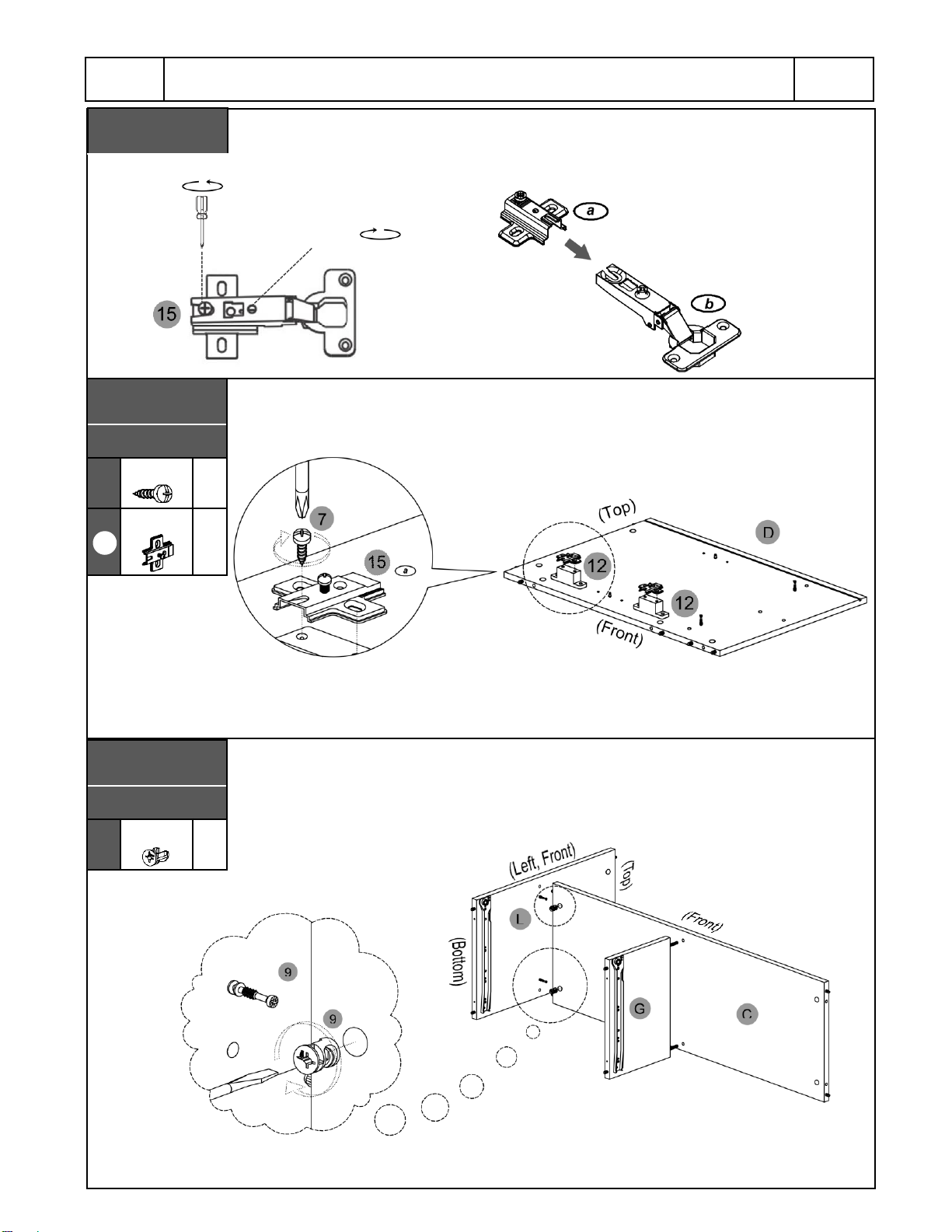
☛This unit uses cam bolts and locks. The following explains how to use them.
This is not an assembly step; it is a guide for when you are actually doing the assembly using this
kind of hardware.
1. Screw the bolt into the
corresponding panel.
2. In the other panel, insert the
cam lock and align it so it can
properly receive the bolt, then join
both panels (the cam locks might
come pre-installed in this unit).
3. The panels might have a very
small gap which is normal; turn the
cam lock clockwise to lock the
parts together and the gap will also
close.
Cam Bolt Cam Lock
ALIGNMENT
DIRECTION
BEFORE YOU START THE ASSEMBLY, PLEASE READ THE FOLLOWING TIPS AND WARNINGS.
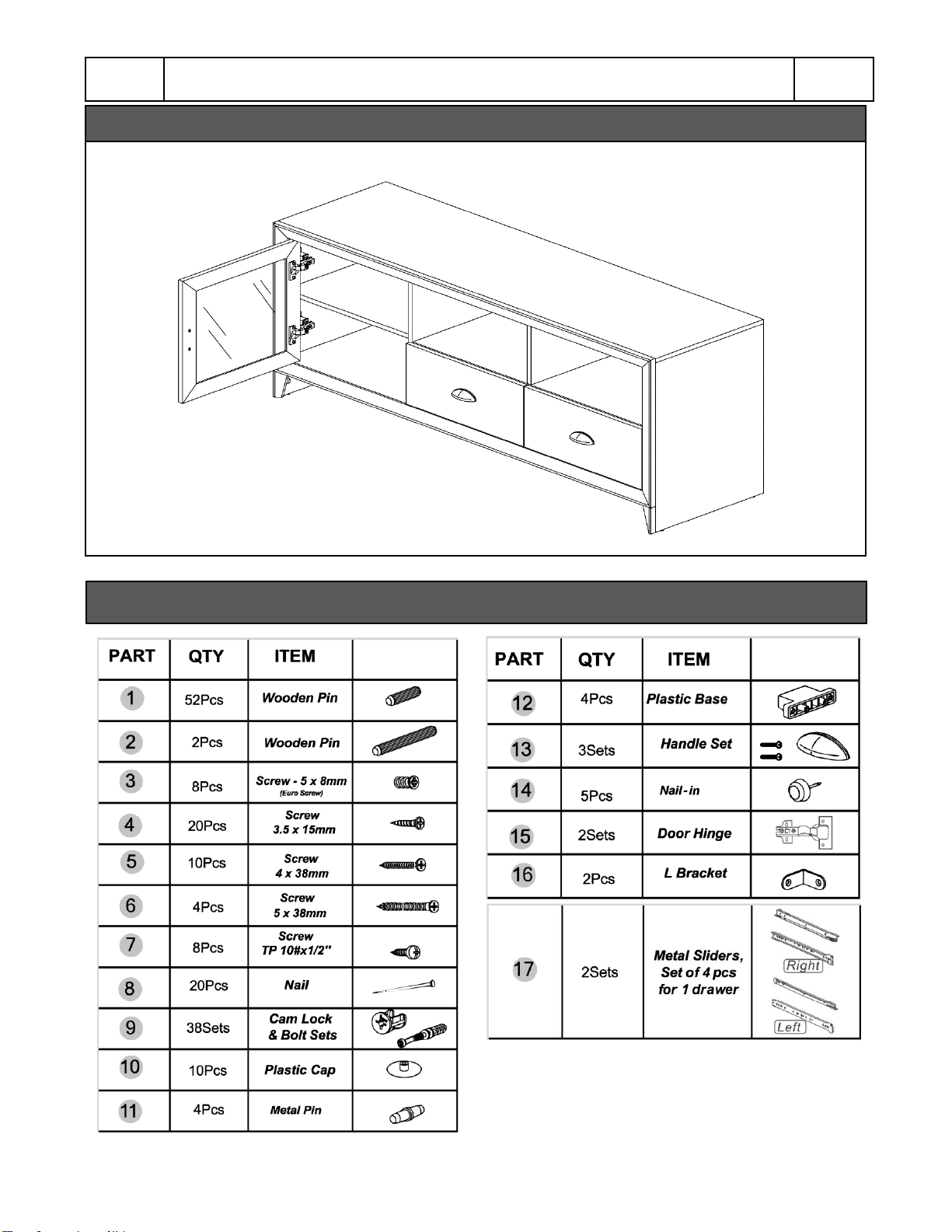
•Do a quick inventory to make sure the product contains all the parts and hardware.
•Missing, damaged and defective parts can be replaced at no cost to you. Please refer to the CONTACT card
included with the product.
•The replacement parts service is limited to the continental United States. If you reside in Hawaii, Puerto Rico,
U.S. Dependencies or other countries, please contact the supplier from where the unit was purchased.
•
If during assembly you find an issue or need clarification, please contact our Customer Service for assistance.
Please refer to the CONTACT card included with the product.
•On each step read the instructions and analyze the illustrations thoroughly before proceeding to do the
assembly.
•Make sure you understand which hardware will be used on each step. Using the wrong size of screw, bolt or
pin might strip the threads or cause damage to the part in which it is being used.
•To avoid misalignments, always leave the screws loose and tighten them until all pieces are positioned
correctly.
•Do not overtighten or force the screws as they might break, strip, damage the threads of the holes or get
stuck inside the part.
•Sometimes the laminate might cover partially or entirely the hole on a panel, but the hole should still be
located under the laminate.
•If there is no visible hole for the screw, pass and press the tip of your finger over the area where the hole
should be located to feel the indentation, and once found, carefully pierce the laminate to reveal the hole
underneath.
•If the hole seems too small for the screw, first make sure you are using the correct size of screw and that it’s
been installed in the correct hole. If the hole still appears to be too small, carefully pierce the laminate to
reveal the hole’s actual size.
P.4
RTA-8807
P.4
ASSEMBLY STEPS
STEP 1
Hardware:
❶
Short Pins
52
Pcs
Install the wooden pins ①into the panels Ⓐ, Ⓑ, Ⓒ, Ⓓ, Ⓔ, Ⓕ, Ⓖ, Ⓗ, Ⓛ, Ⓠand Ⓡin
the corresponding holes as shown in the illustrations, but make sure to use the correct holes
as some are intended for other kind of hardware in subsequent steps.
Insert the wooden pins ②into the top holes of panel Ⓖas shown.
MAKE SURE TO
INSERT THE PINS IN
THE CORRECT HOLES.
STEP 2
Hardware:
❷
Long
Pins 2
Pcs
P.5
RTA-8807
P.5
STEP 3
Hardware:
❾
Cam bolt
22
Pcs
MAKE SURE TO
ATTACH THE BOLTS IN
THE CORRECT HOLES.
Attach the cam bolts ⑨to the corresponding holes on the panels Ⓐ, Ⓓ, Ⓔ, Ⓛ, Ⓞand
Ⓟas shown, but make sure to use the correct holes as some are intended for other kind of
hardware in subsequent steps.
Insert the metal pins ⑪into the corresponding holes on the panels Ⓓand Ⓛas shown.
You can adjust the height for the shelves later on step 26.
STEP 4
Hardware:
⓫
Metal pin
4
Pcs
P.6
RTA-8807
P.6
Use screws ④to assemble the plastic bases ⑫to the panels Ⓓand Ⓔ.
STEP 5
Hardware:
❹
3.5x15mm
8
Pcs
⓬
Base
4
Pcs
STEP 6 Separate all the sliders pieces ⑰according to their shape (no assembly is done here):
-The “Flat” ones go on the side panels of the unit and will be used on the next step.
-The “L” shaped go on the drawers and will be used until step 24, please set them aside.
“FLAT”: Use on next step
“L shaped”: Use until step 20
(2 Sets, total 8 pcs:
4 flats, 4 L shaped)
RIGHT RIGHT
LEFT LEFT
Using screws ③, and paying close attention to the orientation of the parts, assemble:
•One of the right flat sliders ⑰to the plastic bases ⑫on panel Ⓔ.
•One of the left flat sliders ⑰to panel Ⓛ.
•The remaining flat sliders ⑰to panel Ⓖon both sides of the panel.
STEP 7
Screws:
❸
5x8mm
8
Pcs
⓱
Flat
sliders
2 Left
2 Right
Flat, Right
Flat, Left
Flat, Left
Flat, Right
Attach the sliders on both sides.
P.7
RTA-8807
P.7
(Use 2 screws)
(Use 2 screws)
(Use 2 screws)
(Use 2 screws)
ON ALL THE SLIDERS THE WHEEL
FACES DOWN AND TOWARDS THE FRONT
Loosen the screw indicated in the illustration on the hinges ⑮and separate the parts:
•The small parts ⓐwill be used on the next step.
•The big parts ⓑwill be used until step 17, please set them aside.
STEP 9
Hardware:
❼
10#x1/2”
4
Pcs
⓭
Hinge “a”
2
Pcs
You might also need to tighten this
screw a little bit.
Assemble the small hinges ⑮ⓐto the plastic bases ⑫on panel Ⓓusing screws ⑦as
shown.
STEP 8
Small parts ⓐwill be
used on next step.
Big parts ⓑwill be
used until step 21.
15a
PAY ATTENTION TO THE
ORIENTATION OF THE PARTS
1st: Install and align the cam locks ⑨into panel Ⓒin the locations indicated.
2nd: Assemble the panel Ⓛto panel Ⓒas shown and as explained in page 4.
3rd: Join the panel Ⓖto panel Ⓒas shown (wooden pins enter into the holes).
STEP 10
Hardware:
❾
Cam lock
2
Pcs
PAY ATTENTION TO THE
ORIENTATION OF THE PARTS
(Right)
(This view is from the underside of the unit)
SEE PAGE 4
DO NOT REMOVE THE
SCREWS FROM ANY
OF THE 2 PARTS.
P.8
RTA-8807
P.8
Use screws ⑥to assemble the bottom panel Ⓑto panels Ⓖand Ⓛas shown.
STEP 12 Join the bottom crossbar Ⓗto the bottom panel Ⓑas shown (wooden pins enter into the
holes).
STEP 11
Hardware:
❻
5x38mm
4
Pcs
(This view is from the underside of the unit)
STEP 13
Hardware:
❾
Cam lock
6
Pcs
1st: Install and align the cam locks ⑨into panels Ⓑand Ⓒin the locations indicated.
2nd: Assemble panel Ⓓto panel Ⓑas shown and as explained in page 4.
3rd: Assemble panel Ⓔto panels Ⓑand Ⓒas shown and as explained in page 4.
SEE PAGE 4
(This view is from the underside of the unit)
P.9
RTA-8807
P.9
1st: Install and align the cam locks ⑨into panels Ⓓ, Ⓔ, Ⓕand Ⓛin the locations
indicated.
2nd: Assemble the main panel Ⓐto panels Ⓓ, Ⓔ, Ⓕand Ⓛas shown and as explained in
page 4.
STEP 14 Join the upper divider panel Ⓕto the middle shelf Ⓒas shown (wooden pins enter in the
holes).
(This view shows the unit in
the normal upright position)
STEP 15
Hardware:
❾
Cam lock
8
Pcs
SEE PAGE 4
MAKE SURE TO
ATTACH THE BOLTS IN
THE CORRECT HOLES.
Attach the cam bolts ⑨to the corresponding holes on the panels Ⓚ1, Ⓚ2, Ⓘand Ⓙas
shown, but make sure to use the correct holes as some are intended for other kind of
hardware in subsequent steps.
STEP 16
Hardware:
❾
Cam bolt
16
Pcs
P.10
RTA-8807
P.10
(Front)
(Front of panel Ⓐhas
the wooden pins, the
back has the grove)
STEP 18
Hardware:
❽
Nail
20
Pcs
STEP 17
Hardware:
❾
Cam locks
16
Pcs
1st: Install and align the cam locks ⑨into panels Ⓐ, Ⓑ, Ⓓand Ⓔ.
2nd: Assemble the frames Ⓚ1 to panels Ⓐand Ⓑas shown and as explained in page 4.
3rd: Assemble the frames Ⓚ2 to panels Ⓓand Ⓔas shown and as explained in page 4.
4th: Assemble the leg Ⓘto the bottom of panel Ⓓand the leg Ⓙto the bottom of panel Ⓔ
as shown and as explained in page 4.
SEE PAGE 4
(This view is from the underside of
the unit with its front facing UP)
(This view is from the underside of
the unit with its front facing DOWN)
1st: Insert the back panel Ⓥsliding it thru the groves of panels Ⓐ, Ⓓand Ⓔ.
2nd: Nail the back panel Ⓥto panel Ⓑ, and to the panels Ⓕand Ⓛ(behind) using the line
markings as guide.
P.11
RTA-8807
P.11
HOLES FACE TOWARDS THE TOP,
FINISH SURFACE FACES TOWARDS
THE INSIDE.
Attach the nail-in glides ⑭to the bottom corners of panels Ⓓand Ⓔand to the center of
panel Ⓗ.
STEP 21
Screws:
❼
10#x1/2”
4
Pcs
⓯
Hinge “b”
2
Pcs
Assemble the big hinges ⑮ⓑto the glass door Ⓝusing screws ⑦as shown.
P.12
RTA-8807
P.12
Use screws ④to attach the L brackets ⑯to the panels Ⓑand Ⓗas shown.
STEP 19
Screws:
❹
3.5x15mm
4
Pcs
⓰
L Bracket
2
Pcs
(This view is from the underside of
the unit with its front facing DOWN)
(This view is from the underside of
the unit with its front facing DOWN)
STEP 20
Hardware:
⓮
Glides
5
Pcs
Assemble the handle ⑬to the door Ⓝusing the screws that come with it
STEP 22
Hardware:
⓭
Handle
1
Set
STEP 23
Hardware:
❾
Cam lock
6
Pcs
For each the drawer:
1st: Install and align the cam locks ⑨into all the panels Ⓠ, Ⓡand Ⓣ.
2nd: Assemble the panels Ⓠ, Ⓡand Ⓣto panel O as shown and as explained in page 4.
3rd: Assemble the panels Ⓠ, Ⓡand Ⓣto panel P as shown and as explained in page 4.
4th: insert the panel Ⓤthru the groves on panels Ⓞ, Ⓠand Ⓡ.
5th: insert the panel Ⓤthru the groves on panels Ⓟ, Ⓠand Ⓡ.
(This view shows the drawer
with its front facing DOWN)
SEE PAGE 4
SEE PAGE 4
P.13
RTA-8807
P.13
THE HANDLE
OPENING
FACES LEFT
STEP 24
Screws:
❹
3.5x15mm
8
Pcs
❺
4x38mm
10
Pcs
⓱
“L” sliders
2 Left
2 Right
For each the drawer:
1st: Use screws ⑤to assemble the back panel Ⓢto the side panels Ⓠand Ⓡfrom the
sides, and to the support bar Ⓣfrom the back.
2nd: Assemble the “L” shaped sliders ⑰to the side panels Ⓠand Ⓡusing screws ④
as shown.
LEFT
RIGHT
VERY IMPORTANT ABOUT
THE SLIDERS!
INCORRECT:
Raises the
drawer 1” and
won’t fit!
CORRECT:
Sliders don’t
protrude on
the bottom.
(This view shows the drawer
with its front facing DOWN)
THE WHEEL GO
AT THE BACK
STEP 25
Hardware:
❿
Caps
4
Pcs
⓭
Handle
2
Set
For each drawer, assemble the handles ⑬to the front panels Ⓞ, and Ⓟrespectively,
using the screws that come with them, then cover the screws with the plastic caps ⑩.
HANDLE OPENING
FACES DOWN
P.14
RTA-8807
P.14
1st: Insert the drawer with the front panel Ⓞinto the LEFT of the unit.
2nd: Insert the drawer with the front panel Ⓟinto the RIGHT of the unit.
3rd: Insert and place the adjustable panel Ⓜover the metal pins on the left. You can adjust
the location of the panel according to your preference.
4th: Cover the cam locks that are visible at the front of the unit with plastic caps ⑩.
STEP 27 Assemble the door Ⓝto the unit by joining the hinges ⑮ⓑ(on the door) with the hinges
⑮ⓐ(on the plastic bases ⑫) as shown. A little adjustment might be needed if the door
does not close properly, please see instructions below.
DRAWER ⓄTO THE LEFT.
DRAWER ⓅTO THE RIGHT.
STEP 26
Hardware:
❿
Caps
6
Pcs
(This view shows the unit in
the normal upright position)
If the door does not close properly, you
can adjust the alignment of the hinges
by adjusting the following screws:
Adjusts the depth.
DONE! Before you start using the unit, make sure that all the screws, bolts, cam locks,
etc. are properly tightened, and read all the warnings in the next page.
P.15
RTA-8807
P.15
AFTER THE ASSEMBLY IS DONE, PLEASE READ CAREFULLY THE FOLLOWING
CARE AND MAINTENANCE WARNINGS:
•Do not exceed the indicated weight limits.
•Do not expose the surfaces to direct sunlight or to extreme environmental conditions.
•Clean the surfaces preferable with a clean cloth damped in a solution of mild soap and water,
then dry with a
clean towel.
•Do not use solvents or abrasive materials to clean the unit.
•If you decide to use a cleaning agent, test first on an area hidden from view such as underneath the
tabletop.
•Do not seat or stand on the unit.
•Do not allow small children to play over the unit, or inside the left compartment.
•Do not allow small children to reach inside the drawers or any compartment without your supervision.
•The unit must be handled by at least 2 persons when moving in the same or adjacent rooms.
•Before moving the unit, make sure to remove any object that is heavy or might fall off.
•When lifting the unit, use both hands and bend your knees, not your backs.
•When transporting the unit to places far away, protect and secure the unit to avoid damage in transit.
•The glass is made of safety tempered glass. The safety feature is that when breakage occurs, the glass
shatters into many tiny pieces minimizing the risk of serious injuries. If the glass breaks, do not handle the
pieces with your bare hands, take some pictures and contact Customer Service immediately. Please refer to
the Contact Us card.
•Shall any part of the unit become defective during the warranty period, replacement parts might be available
to you at no charge. Please refer to the WARRANTY card included with the product.
•The warranty does not extend to regular wear and tear, nor the manufacturer assumes liability for damages
or consequences due to accidents, incorrect assembly, negligence, improper use, modifications, or not
heeding the above warnings.
•The warranty is limited to the continental United States. If you reside in Hawaii, Puerto Rico, U.S.
Dependencies or other countries, please contact the supplier from where the unit was purchased.
WEIGHT LIMITS
35 Lbs. (15.87 Kg)
55 Lbs. (24.95 Kg)
110 Lbs. (49.89 Kg)
30 Lbs. (13.60 Kg)
35 Lbs. (15.87 Kg)
P.16
RTA-8807
P.16
30 Lbs. (13.60 Kg)
35 Lbs. (15.87 Kg)

Other RTA Indoor Furnishing manuals

RTA Techni Mobili 2338 User manual

RTA

RTA Techni Mobili 2338 User manual

RTA RLR2823 User manual

RTA

RTA RLR2823 User manual

RTA Techni Mobili RTA-KS40 User manual

RTA

RTA Techni Mobili RTA-KS40 User manual

RTA TVM-060 User manual

RTA

RTA TVM-060 User manual

RTA Techni Mobili RTA-7002 User manual

RTA

RTA Techni Mobili RTA-7002 User manual

RTA BLW2330 User manual

RTA

RTA BLW2330 User manual

RTA MEW2973 User manual

RTA

RTA MEW2973 User manual

RTA KODIAK RTA-8830 User manual

RTA

RTA KODIAK RTA-8830 User manual

RTA VOLTERRA 1.20 MLC 4287 User manual

RTA

RTA VOLTERRA 1.20 MLC 4287 User manual

RTA CLIQSTUDIOS User manual

RTA

RTA CLIQSTUDIOS User manual

RTA AUDRA RDW4329 User manual

RTA

RTA AUDRA RDW4329 User manual

RTA CLW2324 User manual

RTA

RTA CLW2324 User manual

RTA RLE2145 Operation instructions

RTA

RTA RLE2145 Operation instructions

RTA LETO User manual

RTA

RTA LETO User manual

RTA Techni Mobili RTA-8412L User manual

RTA

RTA Techni Mobili RTA-8412L User manual

RTA ALCAMO VLE2088 Operation instructions

RTA

RTA ALCAMO VLE2088 Operation instructions

RTA BWM3981 User manual

RTA

RTA BWM3981 User manual

RTA AWD 5421 User manual

RTA

RTA AWD 5421 User manual

RTA Techni Mobili RTA-BC19 User manual

RTA

RTA Techni Mobili RTA-BC19 User manual

RTA ZLD5832 User manual

RTA

RTA ZLD5832 User manual

RTA TECHNI MOBILI RTA-B002 User manual

RTA

RTA TECHNI MOBILI RTA-B002 User manual

RTA TECHNI MOBILI RTA-913D User manual

RTA

RTA TECHNI MOBILI RTA-913D User manual

RTA ASTANA ELW2280 User manual

RTA

RTA ASTANA ELW2280 User manual

RTA Techni Mobili RTA-2018 User manual

RTA

RTA Techni Mobili RTA-2018 User manual

Popular Indoor Furnishing manuals by other brands

Next MADSEN 362596 Assembly instructions

Next

Next MADSEN 362596 Assembly instructions

GFW STOCKHOLM COFFEE TABLE Assembly instructions

GFW

GFW STOCKHOLM COFFEE TABLE Assembly instructions

Kesseböhmer DISPENSA-SWING Assembly instructions

Kesseböhmer

Kesseböhmer DISPENSA-SWING Assembly instructions

GPM SIDHES1DG Assembly instructions

GPM

GPM SIDHES1DG Assembly instructions

RiverRidge 06-035 White Assembly instructions

RiverRidge

RiverRidge 06-035 White Assembly instructions

Vivo DESK-V000K-M2 instruction manual

Vivo

Vivo DESK-V000K-M2 instruction manual

Mocka Edmond Assembly instructions

Mocka

Mocka Edmond Assembly instructions

RiverRidge Monroe 06-182 Assembly instructions

RiverRidge

RiverRidge Monroe 06-182 Assembly instructions

KidKraft Avalon 16601C Assembly instructions

KidKraft

KidKraft Avalon 16601C Assembly instructions

Better Homes and Gardens Lana Modern Cube Bookcase instruction manual

Better Homes and Gardens

Better Homes and Gardens Lana Modern Cube Bookcase instruction manual

Cedam Oakwood Drawer installation instructions

Cedam

Cedam Oakwood Drawer installation instructions

Milwaukee 48-22-8552 Operator's manual

Milwaukee

Milwaukee 48-22-8552 Operator's manual

El Corte Inglés 124-00248 Assembly instructions

El Corte Inglés

El Corte Inglés 124-00248 Assembly instructions

IKEA BENNO instructions

IKEA

IKEA BENNO instructions

Songmics JBC51 Assembly instructions

Songmics

Songmics JBC51 Assembly instructions

College Bed Lofts Short Shelf Assembly instructions

College Bed Lofts

College Bed Lofts Short Shelf Assembly instructions

PAIDI TIAGO 160 instructions

PAIDI

PAIDI TIAGO 160 instructions

pottery barn kids Carolina Craft Table Two Drawer manual

pottery barn kids

pottery barn kids Carolina Craft Table Two Drawer manual

manuals.online logo
manuals.online logoBrands
  • About & Mission
  • Contact us
  • Privacy Policy
  • Terms and Conditions

Copyright 2025 Manuals.Online. All Rights Reserved.