SECTION
1:
INTRODUCTIONAND
SPECIFICATIONS
1.1
INTRODUCTION
RTS Systems, Inc. Model CIF612Camera IS0
Electronics is the electronic heart of a special
intercommunications system. This system allows both
conference-line communication and special, isolated
point-to-point communication. The system consists of
Video Control Panels (the VCP6A or
128)
and user
stations, camera operator user stations, a Source
Assign Panel (the SAP1626), and the Model CIF612.
Up to 6 video control panels and up to 12camera
interfaces canbe used in the system. This special,
isolating capability is known as video IS0or camera
ISO.
In a production or broadcast setting there arevideo
operators and camera operators communicating on
one or more conference-line communication
charnels. When a video operator wants totalk
privately with a particular camera person, the video
operator pushes a switch on the control panel (the
VCP6A or 12B) corresponding to the camera. This
action removes both parties from the conference
channel and places them on
a
completely separate
and isolated channel. Point-to-point communication
is now established between these two people and they
may now carry on a private conversation. Any
combination of up to 12stations may be selected at
the same time. When the conversation is complete,
the video operator again pushes the camera button
and that camera is restored to the conference-line
communication channel.
An additional feature of this system assigns a
particular priority to each video operator's control
panel, either HIGH or LOW. In theory, any video
control panel can IS0any camera at any time. If
another control panel has already selected a camera,
the priority designation comes into play. Control
panels with the same priority assignment can share
the isolated channel, but the HIGH priority control
panel will "take"a given camera line from a LOW
priority panel.
12
DESCRIPTION
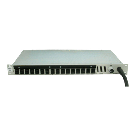
The Model CIF612 is a rack-mounted card cage
containing 12slots for the interface and switching
cards. Slots 2 through
7
arewired to accommodate
the CH612dual camera interface circuit cards. Slots
8
through
13
arewired to accommodate the SW612
IS0control/switch cards. Up to six of each type of
card may be used. The first slot on the right and left
sides of the unit are not functional. An extender card
is provided with each unit and is located in one of the
non-functional card slots. You may wish to order a
spare of each type of card and install them in the non-
functional slots to minimize interruption in case of
component failure. The front panel is hinged to allow
easy access. The reverse of the front panel is labeled
with all the circuit card adjustment information.
Each circuit card features on-board power regulalion
and filtering, and anLED which shows power status.
All active cards connect to the motherboard matrix
through gold plated card edge fingerson the back of
the card.
Level and balance adjustments for the unit are located
just behind the hinged front panel. The reverse side
of the front panel contains a legend explainingthe
location and function of all of the controls.
13
POWER REQUIREMENTS
The Model CIF612 requires 14volts AC or 16volts
DC to operate. The unit is shipped with a power
supply which provides the necessary voltage.
1.4
CONNECTIONS
All connections toand from the CIF612 are found on
the back panel. The control panels connect to
50
pin
female microribbon connectors. Each camera's four
wire intercom signal cable connects to a 5-pin male
XLR
type connector. A 25-pin D connector provides
connection to the SAP1626 so that each camera may
be assigned one of the non-iso intercom
channels.


