manuals.online logo
Brands
  1. Home
  2. •
  3. Brands
  4. •
  5. RTS
  6. •
  7. Intercom System
  8. •
  9. RTS User Station MCE-325 User manual

RTS User Station MCE-325 User manual

Other manuals for User Station MCE-325

4

Other RTS Intercom System manuals

RTS RVON-I/O User manual

RTS

RTS RVON-I/O User manual

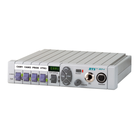
RTS RKP-4 User manual

RTS

RTS RKP-4 User manual

RTS MC-ADAM-CS User guide

RTS

RTS MC-ADAM-CS User guide

RTS SSA-324 User manual

RTS

RTS SSA-324 User manual

RTS SSA-424A User manual

RTS

RTS SSA-424A User manual

RTS 802 Instruction manual

RTS

RTS 802 Instruction manual

RTS KP-12 User manual

RTS

RTS KP-12 User manual

RTS XCP-40-DB9 Quick start guide

RTS

RTS XCP-40-DB9 Quick start guide

RTS SSA-424 User manual

RTS

RTS SSA-424 User manual

RTS KP-32 User manual

RTS

RTS KP-32 User manual

RTS EKP-832 User manual

RTS

RTS EKP-832 User manual

RTS MC-ADAM Installation instructions

RTS

RTS MC-ADAM Installation instructions

RTS WMS300 User manual

RTS

RTS WMS300 User manual

RTS KP-12 User guide

RTS

RTS KP-12 User guide

RTS ARP-32 User manual

RTS

RTS ARP-32 User manual

RTS UIO-256 User manual

RTS

RTS UIO-256 User manual

RTS Zeus II User manual

RTS

RTS Zeus II User manual

RTS XCP-32-DB9 Quick start guide

RTS

RTS XCP-32-DB9 Quick start guide

RTS BTR-800 User manual

RTS

RTS BTR-800 User manual

RTS Bus Expansion Card Instruction Manual

RTS

RTS Bus Expansion Card Instruction Manual

RTS TIF-4000 Frame User manual

RTS

RTS TIF-4000 Frame User manual

RTS MC-ADAM-CS User guide

RTS

RTS MC-ADAM-CS User guide

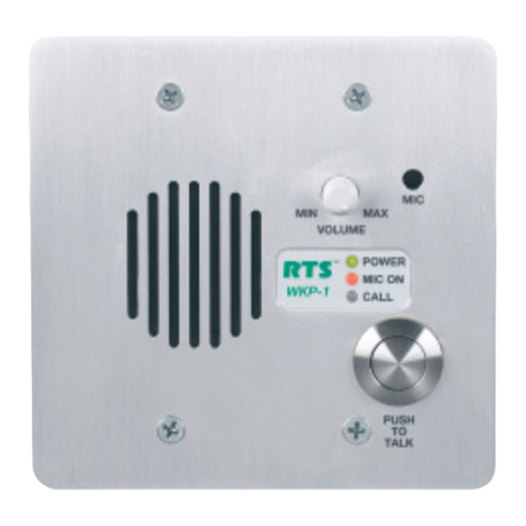
RTS WKP-1 User manual

RTS

RTS WKP-1 User manual

RTS Digital Matrix Intercom RVON-8 User manual

RTS

RTS Digital Matrix Intercom RVON-8 User manual

Popular Intercom System manuals by other brands

Videx VRDK1 (25H) Technical manual

Videx

Videx VRDK1 (25H) Technical manual

Auta COMPACT VISUALTECH manual

Auta

Auta COMPACT VISUALTECH manual

Aiphone LC-10S instructions

Aiphone

Aiphone LC-10S instructions

Aiphone PD-1 instructions

Aiphone

Aiphone PD-1 instructions

Aiphone JF-DVF-HID-I instructions

Aiphone

Aiphone JF-DVF-HID-I instructions

Comelit 4893M Technical manual

Comelit

Comelit 4893M Technical manual

MGL Avionics V16 manual

MGL Avionics

MGL Avionics V16 manual

SSS Siedle BVI 750-0 Installation & programming

SSS Siedle

SSS Siedle BVI 750-0 Installation & programming

urmet domus AIKO 1716/1 quick start guide

urmet domus

urmet domus AIKO 1716/1 quick start guide

urmet domus IPerVoice 1039 Installation

urmet domus

urmet domus IPerVoice 1039 Installation

Alpha Communications STR QwikBus TT33-2 Installation, programming, and  user's manual

Alpha Communications

Alpha Communications STR QwikBus TT33-2 Installation, programming, and user's manual

Monacor ICM-20H instruction manual

Monacor

Monacor ICM-20H instruction manual

Logenex A202CR Installation & programming

Logenex

Logenex A202CR Installation & programming

Quantum QR5 Installation and programming manual

Quantum

Quantum QR5 Installation and programming manual

EVGA XR1 quick guide

EVGA

EVGA XR1 quick guide

CyberData 011211 series Installation quick reference

CyberData

CyberData 011211 series Installation quick reference

Vidos duo M1021 user manual

Vidos

Vidos duo M1021 user manual

Savant DOR-SMS-00 Deployment guide

Savant

Savant DOR-SMS-00 Deployment guide

manuals.online logo
manuals.online logoBrands
  • About & Mission
  • Contact us
  • Privacy Policy
  • Terms and Conditions

Copyright 2025 Manuals.Online. All Rights Reserved.

MCE-325
User Station
The MCE-325 is a four-channel, programmable intercom station. It may be used as a headset station or, with the addition of
the MCS-325 Modular Speaker, as a speaker station. It may be mounted in a console or equipment rack via optional mounting
kits. The MCE-325 can be used with either two-wire or four-wire intercom lines, or a combination of both. In the labeling on the
MCE-325, references to channels 1, 2, 3, and 4 indicate two-wire lines; references to four-wire A and four-wire B indicate four-
wire lines. The MCE-325 can be interfaced to a variety of external devices including external program sources, two-way radios,
paging systems, and satellite circuits.
Call Signaling
Call signaling is accomplished using an inaudible (20 kHz)
signal to activate a call indicator LED.
Remote “talk-off”
Active, unattended remote station microphones may be
deactivated by momentarily injecting an inaudible (24 kHz)
signal into the corresponding intercom line. The MCE-325
can send and receive “talk-off” signals.
VOX circuit
The MCE-325 may be programmed for voice activation of
the microphone.
Simple IFB
Program audio assigned to a channel is interrupted during
talk.
External device keying
External devices, such as two-way radios, speaker mute
relays, or paging systems may be activated through key
outputs at the auxiliary connector on the rear panel. The key
outputs may also be used to expand the simple IFB function,
allowing any one of a number of MCE-325 stations to inter-
rupt the program source and talk on the line.
Microphone Limiter
The microphone preamplier circuit contains a limiter, which
helps to equalize voice levels.
Fully programmable
Retains programming even when power is shut off.
Instantaneous Auto-Reset
Instantaneous Auto Reset (IAR), the newest technology in
performance and safety, which uses a revolutionary new
circuitry that dynamically monitors line fault conditions. Then,
when the fault is removed, automatically brings individual
power supply channels up.
Features
Line Drawing
MCE-325 Specications
General
Bridging Impedance (to line) 10,000 Ω typical
Noise Contribution to 200 Ω Line -90 dBu
Call Signal Frequency 20 kHz, crystal controlled
Talk-off Frequency 24 kHz, crystal controlled
Microphone Preamplier
Maximum Voltage Gain 54 dB
Frequency Response 100 Hz to 8,000 Hz, ±3 dB
Input Impedance 1,000 Ω
Limiter Range 30 dB
Headphone Amplier
Maximum Voltage Gain 30 dB
Frequency Response 100 Hz to 8,000 Hz, ±3 dB
Headphone Impedance 50 to 600 Ω
Output Power 150 mW into 50 Ω
Output Voltage Level 8 Vp-p
Speaker Amplier
Maximum Voltage Gain 30 dB
Frequency Response 100 Hz to 8,000 Hz, ±3 dB
Speaker Impedance 8 to 16 Ω
Output Power per Amplier 5W into 8 Ω
Output Voltage Level 16 Vp-p
Power and Mechanical
Power Requirements 115 or 230 VAC, 20 VA max version available
12 to 25 VDC, 100 to 125 mA quiescent, 900 mA max
Dimensions 1.72” (44 mm) tall, 8.2” (208 mm) wide, 8” (203 mm) deep
Weight 4.5 lbs (1.93kg)
Material/Finish Thermo-plastic front panel, aluminum case, light gray nish
Connectors
Intercom Line Connector XLR type, 3-pin (male-female loop through on two-wire
Channel 1 and 2, or four-wire channel A; Female only on two-wire channel 3 and 4, or four-wire channel B
Dynamic Mic XLR type, 6-pin female
Carbon Mic ¼-inch phone jack, 3-circuit
Auxiliary Connector 25-pin, female, D-Sub
Program Inputs ¼-inch phone jack, 3-circuit
Speaker Output ¼-inch phone jack, 3-circuit
Panel Mic ¼-inch phone jack, metal busing, 3-circuit
Ordering Information
MCE-325 A5F • 2 or 4 channel user programmable
modular user station • Catalog Number: 9000646400
MCE-325 A4F • 2 or 4 channel user programmable
modular user station with A4M headset connector, UL
approved • Catalog Number: 9000646401
This specications information is preliminary and is subject to change without notication.
Brand names mentioned are the property of their respective companies.
Contact Information
Telex Communications, Inc.
12000 Portland Avenue South
Burnsville, Minnesota 55337
Telephone: (800) 392-0498
Fax: (800) 323-0498
Form Number: 38110-342
Date: March, 2006