Copyright © 2011 Ruckus Wireless, Inc.
Published February 2011, Part Number 800-70311-001
1 in./2.54 cm
Mounting Template
Scale
STEP 4: CUSTOMIZE THE WIRELESS SETTINGS
1Log in to the ZoneFlex Web interface.
For single band AP (ZoneFlex 7343):
• On the Web interface menu, click Configuration > Wire-
less. The Configure::Wireless::Common options appear.
• Verify that the following options are active:
•Wireless Mode: Auto-select
•Channel: SmartSelect
•Country Code: If you are not located in the United
States, select your current country.
For dual band AP (ZoneFlex 7363):
• On the Web interface menu, click Configuration > Radio
2.4G or Configuration > Radio 5G.
• Verify that the following options are active:
•Wireless Mode: Radio 2.4G or Radio 5G
•Channel: SmartSelect
•Country Code: If you are not located in the United
States, select your current country.
• Click Update Settings if you made any changes.
2Click any of the “Wireless #” tabs near the top of the screen.
3In Wireless Availability, click Enabled.
4Delete the text in the SSID field, and then type the name of
your network. If your network does not have a “name”, type
a short name that will help your users identify the AP in their
wireless network connection application.
5Click Update Settings to save your changes.
6Repeat Steps 4-6 for each Wireless # interface that you want
to enable.
7Click Logout to exit the Ruckus Web Admin interface.
8When the Web Admin login page reappears, you can exit
your browser.
9Disconnect the AP from the computer and from the current
power source, and then restore your computer to the nor-
mal network connections.
STEP 5: RESTORE YOUR COMPUTER’SNETWORK SET-
TINGS
1Click Start > Settings > Network Connections.
(If Windows 2000, click Start > Settings > Network and
Dial-up Connections.)
2When the Network Connections window appears, right-click
the icon for the “Local Area Connection” designated for
your home network and choose Properties.
3When the Local Area Connection Properties dialog box
appears, select Internet Protocol (TCP/IP) from the scrolling
list, and click Properties.
The TCP/IP Properties dialog box appears.
4Restore your original TCP/IP settings from your standard
network configuration (which you recorded in Step 2).
5Click OK to save your settings and exit first the TCP/IP Prop-
erties dialog box, then the Local Area Connection Proper-
ties dialog box.
Your computer is now ready for normal network use.
STEP 6: PLACE THE AP IN YOUR SITE
1Disconnect the AP’s power adapter from the power outlet
(or disconnect the PoE cable).
2Move the AP to its permanent location (accessible to both
AC power and network connections).
3Use an Ethernet cable to connect the 10/100 or 10/100/1000
port of the AP to the appropriate device:
• The ISP’s modem or gateway device
• The Ethernet switch that is connected to the ISP’s device
4If not using Power over Ethernet, connect the AP power
adapter to the AP, then to a convenient power source.
5Verify that the Ethernet port LED is lit.
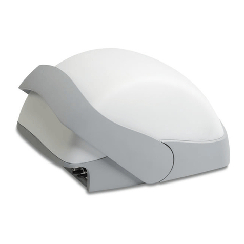
Using the cable cover:
After a short pause to re-establish the Internet connection, you
can test the AP.
STEP 7: VERIFY THE INSTALLATION
1Using any wireless-enabled computer or mobile device,
search for and select the wireless network you’ve previously
configured.
2If you can connect, open a browser and link to any public
Web site.
Congratulations! Your wireless network is active and ready for
use.
OPTIONAL: IF YOU WANT TO SWITCH FROM DHCP
(DEFAULT)
If you anticipate logging into the AP regularly to perform
monitoring or maintenance (once it is in place), you may want to
consider assigning a static IP address to the AP.
In a default AP configuration, the AP uses a DHCP-assigned
IP address.
A. On the menu, click Configuration > Internet.
B. Click the Static IP option.
C. Fill in the IP Address and Mask fields.
D. Click Update Settings to save your changes.
TIP: Follow these guidelines to maximize wireless signal
performance:
• Place the AP as close to the center of the room, and away
from any physical obstructions, as possible.
• Place the AP on a shelf or other elevated location where the
user’s wireless networking devices are in line-of-sight
access.
• Alternatively, the AP can be mounted to the ceiling using
the mounting holes on the under side of the unit.
• Avoid any sources of electromagnetic interference.
• Avoid placing the AP near large metal or glass surfaces.
Note: If you will be using PoE, you will need a Cat-5e (or
better) Ethernet cable to connect the AP to the PoE injector
or switch.
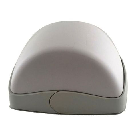
Note: If using the supplied cable cover, first remove the
rubber feet from the bottom of the AP, then attach all
necessary cables to the AP before sliding the cable cover
onto the cable end of the housing with cables exiting
toward the bottom side. of the AP. Slide the cover onto the
AP until it snaps in place over the two protruding feet on the
bottom of the AP, as shown.
