RUD INOX-STAR User manual

1
INOX-STAR
EN
RUD Ketten
Rieger & Dietz GmbH u. Co. KG
73428 Aalen
Tel. +49 7361 504-1370
Fax +49 7361 504-1171
www.rud.com
RUD-Art.-Nr.: 7996554-EN / 03.021
Eye bolts made out of
DUPLEX stainless steel
> INOX-STAR <
Safety instructions
This safety instruction/declaration of the manufacturer has to be
kept on le for the whole lifetime of the product.
Translation of the Original instructions
EG-Konformitätserklärung
entsprechend der EG-Maschinenrichtlinie 2006/42/EG, Anhang II A und ihren Änderungen
Hersteller:
RUD Ketten
Rieger & Dietz GmbH u. Co. KG
Friedensinsel
73432 Aalen
Hiermit erklären wir, dass die nachfolgend bezeichnete Maschine aufgrund ihrer Konzipie-
rung und Bauart, sowie in der von uns in Verkehr gebrachten Ausführung, den grundle-
genden Sicherheits- und Gesundheitsanforderungen der EG-Maschinenrichtlinie
2006/42/EG sowie den unten aufgeführten harmonisierten und nationalen Normen sowie
technischen Spezifikationen entspricht.
Bei einer nicht mit uns abgestimmten Änderung der Maschine verliert diese Erklärung ihre
Gültigkeit.
Produktbezeichnung: INOX-Star
_____________________________________________
_____________________________________________
Folgende harmonisierten Normen wurden angewandt:
DIN EN ISO 12100 : 2011-03
_________________ _________________
_________________ _________________
_________________ _________________
_________________ _________________
_________________ _________________
Folgende nationalen Normen und technische Spezifikationen wurden außerdem angewandt:
BGR 500, KAP2.8 : 2008-04
_________________ _________________
_________________ _________________
_________________ _________________
_________________ _________________
_________________ _________________
Für die Zusammenstellung der Konformitätsdokumentation bevollmächtigte Person:
Michael Betzler, RUD Ketten, 73432 Aalen
Aalen, den 26.09.2016
Dr.-Ing. Arne Kriegsmann,(Prokurist/QMB)
_____________________________________________
Name, Funktion und Unterschrift Verantwortlicher
EC-Declaration of conformity
According to the EC-Machinery Directive 2006/42/EC, annex II A and amendments
Manufacturer:
RUD Ketten
Rieger & Dietz GmbH u. Co. KG
Friedensinsel
73432 Aalen
We hereby declare that the equipment sold by us because of its design and construction,
as mentioned below, corresponds to the appropriate, basic requirements of safety and
health of the corresponding EC-Machinery Directive 2006/42/EC as well as to the below
mentioned harmonized and national norms as well as technical specifications.
In case of any modification of the equipment, not being agreed upon with us, this declara-
tion becomes invalid.
Product name:
INOX-STAR
_____________________________________________
_____________________________________________
The following harmonized norms were applied:
DIN EN ISO 12100 : 2011-03
_________________ _________________
_________________ _________________
_________________ _________________
_________________ _________________
_________________ _________________
The following national norms and technical specifications were applied:
BGR 500, KAP2.8 : 2008-04
_________________ _________________
_________________ _________________
_________________ _________________
_________________ _________________
_________________ _________________
Authorized person for the configuration of the declaration documents:
Michael Betzler, RUD Ketten, 73432 Aalen
Aalen, den 26.09.2016
Dr.-Ing. Arne Kriegsmann,(Prokurist/QMB)
_____________________________________________
Name, function and signature of the responsible person

2INOX-STAR
Before every use, please read the Safety
Instruction of the INOX-STAR carefully
and make sure that you understand all
substance.
Improper use or care of this eyebolt can
result in bodily injury or property damage
and eliminates any warranty!
1 Application and warning information
WARNING
Improper assembled or damaged INOX-
STAR and inappropriate use can result in
deadly injury or lead to heavy injuries when
load drops. Inspect the INOX-STAR before
each use carefully!
The INOX-STAR must only be used by competent and
trained people with adequate knowledge respecting
BGR/DGUV 100-500 requirements, and outside Ger-
many the corresponding country specic requirements
must be utilised.
2 Intended use of INOX-STAR
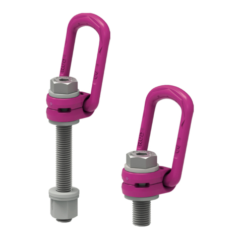
The eyebolt INOX-STAR can be used as a lifting point
in general.
The INOX-STAR must not be used when load
swivels, because the INOX-STAR could turn loose.
The lifting point must only be used up to the maximum
required WLL (see chart 2).
The INOX-STAR eyebolt must only be used in the
hereby specied application.
3 Material properties
The utilised stainless Duplex-steel 1.4462 for the
body and the bolt has a good resistance against
wear and local corrosion like pitting, crevice corrosion
and stress corrosion cracking in sea water and high
chloride and H2S containing media.
This steel is very common in the construction industry,
chemical industry, oil industry, food industry (only
limited resistance against lactic acid), in the machine
engineering for example, as REA-components and
transport boxes, in desalting plants at OFF-Shore
areas like shipbuilding.
The material can also be utilised in the nuclear in-
dustry as far as nuclear technical requirements or
object specications do allow the usage (according
to VdTÜV 418).
HINT
The material must not be used in the
following areas:
Load bearing parts in indoor swimming pool
atmospheres, which are neither permanent
rinsed with water nor cleaned, if their failure
could cause serious personal injury.
For example when used as connecting
element for a suspended ceiling, pendents
or loudspeakers or for the xation of water
slides or any other construction elements (read
ISER-Merkblatt 831).
4 Installation information
4.1 General information
• Capability of temperature usage:
The stainless steel PSA-INOX-STAR eye bolts can
be used in the temperature range between -60°C
up to 280°C (according to VdTÜV 418).
• RUD lifting points must not be used under chemical
inuences such as acids, alkaline solutions and
vapours. Please observe chapter 2, Intended use
of INOX-STAR and chapter 3 Material properties.
4.2 Assembly information
1. The material construction to which the lifting point
will be attached should be of adequate strength to
withstand forces during lifting without deformation
(certicate of static forces). Rm > 340 N/mm²
For steel of the strength S235JR (1.0037) or Cast
iron GG 25 (0.6025 - without blowhole) the bolt
length should be 1,5xM (=L).
When lifting light metals, nonferrous metals
and gray cast iron or other materials the thread
has to be chosen in such a way that the WLL
of the thread corresponds to the requirements
of the corresponding base material. For ma-
terial with lower strength, please use lifting
points with longer thread engagement.
German employers insurance association (BG/
DGUV) recommends the following minimum
thread engagement lengths:
2 x M in aluminium alloys
2,5 x M in light metal with low strength.
Please choose for light metals, nonferrous metals
and grey cast iron or other materials the thread
has to be chosen in such a way that the WLL of
the thread corresponds to the requirements of the
corresponding base material.
2. The bolting location for the eyebolt should be mar-
ked with paint.
3. The eyebolt should be installed as follows:
- the coupling element must be free moveable,
- locate lifting point in such a way that prohibited
loading, like turning or ipping of the load will be
avoided:
- Single fall lifting: vertical, above centre of
gravity.
- Double leg lifting: over and at each side
of the centre of gravity.
- Three- or 4 leg lifting: equal in the same
level around centre of gravity.

3
INOX-STAR
4. Symmetry of load:
Determine the necessary WLL of each lifting
point for symmetrical and unsymmetrical loading
according to the following physical calculation
correlation:
WLL = necessary working load limit of the single
lifting point (kg)
G = weight of load (kg)
n = number of load bearing
ß = inclination angle of single strand
WLL=G
n x cos ß
Number of load bearing strands:
Symmetric Unsymmetric
Double strand 2 1
Three-/ Four strand 3 1
(see also chart 2)
5. Make sure that a plane bolting surface is provided
(Ø E, see chart 1). Maximum countersink of the
threaded hole = Nominal diameter of thread
6. Drill the tapped blind holes deep enough so that
the shoulder of the INOX-STAR bolt sits properly
on the plane surface. Machine through holes up
to DIN EN 20273-middle.
7. The INOX-STAR must be adjustable through 360°
when installed.
- For a temporary assembly, hand tightening
with an allen key is sucient.
- If the INOX-STAR shall be installed permanent-
ly, a torque of 25 Nm (+/- 10 %) must be ap-
plied, plus securing with threadlocker has to be
done. It is possible to receive a socket wrench
for the usage of a torque:
Type metric Torque Part-No.
key
INOX-STAR M12 25 Nm 7997750
INOX-STAR M16 60 Nm 7997751
INOX-STAR M20 115 Nm 7997752
INOX-STAR M24 190 Nm 7997753
table 1
Secure in general all lifting points which are
installed permanently, e.g. with glue.
HINT
Shock loading or vibrations can cause
unintentional dismantling. To avoid this use
liquid thread locker such as Loctite or WEI-
CONLOCK (depending on the application,
please pay attention to the manufacturer’s
instruction).
Attention: Ring Body has to be free rota-
table.
8. After the installation has been done, a competent
person should check the suitability of the fall pro-
tection eyebolt (see chapter 5, Inspection criteria).
4.3 User information
• Inspect INOX-STAR eyebolt regularly before
each usage in regard of tightening, corrosion, wear,
deformation etc. (see chapter 5 Inspection criteria).
WARNING
Wrong assembled or damaged lifting me-
ans as well as incorrect usage may result
in serious or deadly injuries.
Lifting means must be in general inspected
before each usage.
• If a safe usage is doubtable or if the lifting mean
has been stressed by a dropped load, for safety
reasons the usage must be withdrawn.
A competent person must decide whether the lifting
mean can be used further on.
• The INOX-STAR has to be adjustable through 360°
when tted and with key disengaged. Adjust to di-
rection of pull before attaching of the lifting mean.
HINT
Attention: INOX-STAR eyebolts are not
suited for turning under load!
• Please observe that the lifting mean connected
to the INOX-STAR should be free moving. When
connecting and disconnecting the lifting means
(sling chain, round loop, wire rope) pinches and
impacts should be avoided. Damage of the lifting
means caused by sharp edges should be avoided
as well.
• Eliminate any damage of the INOX-STAR for
example caused by loading on sharp edges.
• If the INOX-STAR is used exclusively for lashing,
the value of the working load limit can be doubled.
LC = 2 x WLL
4.4 Hints for the regular inspection
In time periods complying to the need or usage a
technical expert should control at least once a year
the appropriateness of the lifting point. This inspec-
tion must also be done after each event of damage
or special incident.
5 Inspection criteria
Observe and control the following points before each
usage in regular periods, after assembly and after
special incidents:
• Bolt tightening (torque)
• Completeness of the lifting point
• Complete, readability of the Working Load Limit
(WLL) as well as existing sign of manufacturer
• Deformation on load bearing parts like basic body
and bolt
• Mechanical damages like notches, especially when
located in areas of tensile stress
• strong corrosion
• Reduction of cross section caused by wear > 10 %
• Function and damage of bolts and threads
• Easy turning of the ring, free of jerk must be assured

4INOX-STAR
table 3 Subject to technical alterations
table 2
Methode of lift
G
G
G
G
G
G
G
G
Number of strands 1 1 2 2 2 2 2 3/4 3/4 3/4
Inclination angle <ß 0-7° 90° 0-7° 90° 0-45° 45°-60° Unsymm. 0-45° 45°-60° Unsymm.
Factor 1 1 2 2 1.4 1 1 2.1 1.5 1
Type metric for max. load weight t in Tons. tightened and adjusted to the load direction
INOX-STAR M12 1.2 0.5 2.4 1 0.71 0.5 0.5 1.06 0.75 0.5
INOX-STAR M16 2.4 1 4.8 2 1.4 1 1 2.1 1.50 1
INOX-STAR M20 3.6 2 7.2 4 2.8 2 2 4.25 3 2
INOX-STAR M24 5.2 2.5 10.4 5 3.5 2.5 2.5 5.25 3.75 2.5
Type metric for max. load weight in lbs. tightened and adjusted to the load direction
INOX-STAR M12 2640 1100 5280 2200 1550 1100 1100 2330 1650 1100
INOX-STAR M16 5290 2200 10580 4400 3110 2200 2200 4660 3300 2200
INOX-STAR M20 7900 4400 15800 8800 6220 4400 4400 9330 6600 4400
INOX-STAR M24 11450 5500 22900 11000 7770 5500 5500 11660 8250 5500
At a lift with one strand and two parallel strands where
the inclination angles are at the max. ± 7°, the lifting
methode can be assumed as a vertical lift.
When lifting with two, three or four leg lifting means, inclination angles of less
than 15° shall be avoided, if possible (Risk of instability).
Type WLL
[t]
weight
[kg/
pc.]
T
[mm]
B
[mm]
C
[mm]
D
[mm]
E
[mm]
G
[mm]
I
[mm]
K
[mm]
L
[mm]
M N
[mm]
torque
[Nm]
Ref.-No.
INOX-STAR - metric
INOX-STAR M12 0,5 0,19 43 14 12 30 30 32 18 56 18 M12 8 25 7993835
INOX-STAR M16 1 0,31 50 16 14 35 36 38 22 65 24 M16 10 60 7993836
INOX-STAR M20 2 0,53 58 19 16 40 43 47 27,5 74 30 M20 12 115 7993837
INOX-STAR M24 2,5 0,92 70 24 19 48 51 56 33 92 36 M24 14 190 7993838
INOX-STAR - metric special length
INOX-STAR M12 0,5 0,22 43 14 12 30 30 32 18 56 50 M12 8 25 7997822
INOX-STAR M16 1 0,35 50 16 14 35 36 38 22 65 50 M16 10 60 7910089
INOX-STAR M20 2 0,6 58 19 16 40 43 47 27,5 74 60 M20 12 115 7998714
HINT
Translation of the original instruction manual
In case of doubts or misunderstandings, the
German version of this document is decisive.
RUD components are tested in accordance with
DIN EN 1677, with a minimum of 20.000 load
cycles at 1.5 x WLL.
Employers insurance association (BG/DGUV)
recommends: At high dynamic stress with a high
number of load cycles (permanent usage), the
bearing stress must be reduced acc. to FEM
with 1BM (M3 acc. to DIN EN 818-7), e.g. by
using the next bigger nominal size.
Other RUD Safety Equipment manuals
Popular Safety Equipment manuals by other brands

Milwaukee
Milwaukee BOLT User instructions

Carl Stahl Kromer
Carl Stahl Kromer EASY BALANCER ER00 Series operating instructions

Guardio
Guardio ARMET VOLT product manual

Würth
Würth BFD Instructions for use

Milwaukee
Milwaukee M12 204 Series Operator's manual

Sordin
Sordin left/RIGHT Active FM Pro Product description

Simply Brands
Simply Brands RATCHET TIE DOWN instruction manual

SICK
SICK TTC100-2 ADDENDUM TO OPERATING INSTRUCTIONS

ProMobility
ProMobility M27 user guide

Promeba
Promeba PS-182 user guide

ABS Safety
ABS Safety ABS-Lock X-First II Series installation manual

AmazonBasics
AmazonBasics B08DRNXDX8 quick start guide