RUD VLBG-PLUS User manual

1VLBG-PLUS
Load ring VLBG-PLUS
for bolting (ICE-PINK)
RUD Ketten
Rieger & Dietz GmbH u. Co. KG
73428 Aalen/Germany
Tel. +49 7361 504-1370
Fax +49 7361 504-1460
www.rud.com
Load ring for bolting
>VLBG-PLUS<
Safety instructions
This safety instruction/declaration of the manufacturer has to be kept on
le for the whole lifetime of the product.
– Translation of the Original instructions –
EG-Konformitätserklärung
entsprechend der EG-Maschinenrichtlinie 2006/42/EG, Anhang II A und ihren Änderungen
Hersteller:
RUD Ketten
Rieger & Dietz GmbH u. Co. KG
Friedensinsel
73432 Aalen
Hiermit erklären wir, dass die nachfolgend bezeichnete Maschine aufgrund ihrer Konzipie-
rung und Bauart, sowie in der von uns in Verkehr gebrachten Ausführung, den grundle-
genden Sicherheits- und Gesundheitsanforderungen der EG-Maschinenrichtlinie
2006/42/EG sowie den unten aufgeführten harmonisierten und nationalen Normen sowie
technischen Spezifikationen entspricht.
Bei einer nicht mit uns abgestimmten Änderung der Maschine verliert diese Erklärung ihre
Gültigkeit.
Produktbezeichnung: Lastbock VLBG-PLUS
_____________________________________________
_____________________________________________
Folgende harmonisierten Normen wurden angewandt:
DIN EN 1677-1 : 2009-03 DIN EN ISO 12100 : 2011-03
_________________ _________________
_________________ _________________
_________________ _________________
_________________ _________________
_________________ _________________
Folgende nationalen Normen und technische Spezifikationen wurden außerdem angewandt:
BGR 500, KAP2.8 : 2008-04
_________________ _________________
_________________ _________________
_________________ _________________
_________________ _________________
_________________ _________________
Für die Zusammenstellung der Konformitätsdokumentation bevollmächtigte Person:
Michael Betzler, RUD Ketten, 73432 Aalen
Aalen, den 26.09.2016
Dr.-Ing. Arne Kriegsmann,(Prokurist/QMB)
_____________________________________________
Name, Funktion und Unterschrift Verantwortlicher
EC-Declaration of conformity
According to the EC-Machinery Directive 2006/42/EC, annex II A and amendments
Manufacturer:
RUD Ketten
Rieger & Dietz GmbH u. Co. KG
Friedensinsel
73432 Aalen
We hereby declare that the equipment sold by us because of its design and construction,
as mentioned below, corresponds to the appropriate, basic requirements of safety and
health of the corresponding EC-Machinery Directive 2006/42/EC as well as to the below
mentioned harmonized and national norms as well as technical specifications.
In case of any modification of the equipment, not being agreed upon with us, this declara-
tion becomes invalid.
Product name:
Load ring VLBG-PLUS
_____________________________________________
_____________________________________________
The following harmonized norms were applied:
DIN EN 1677-1 : 2009-03 DIN EN ISO 12100 : 2011-03
_________________ _________________
_________________ _________________
_________________ _________________
_________________ _________________
_________________ _________________
The following national norms and technical specifications were applied:
BGR 500, KAP2.8 : 2008-04
_________________ _________________
_________________ _________________
_________________ _________________
_________________ _________________
_________________ _________________
Authorized person for the configuration of the declaration documents:
Michael Betzler, RUD Ketten, 73432 Aalen
Aalen, den 26.09.2016
Dr.-Ing. Arne Kriegsmann,(Prokurist/QMB)
_____________________________________________
Name, function and signature of the responsible person
RUD-Art.-Nr.: 7907302-EN /03.19
EN

VLBG-PLUS2
Please read user instruction before initial op-
eration of the bolt-on lifting point VLBG-PLUS.
Make sure that you have comprehended all
subjected matters.
Non observance can lead to serious personal
injuries and material damage and eliminates
warranty.
1 Safety instructions
ATTENTION
Wrong assembled or damaged VLBG-PLUS as
well as improper use can lead to injuries of per-
sons and damage of objects when load drops.
Please inspect all VLBG-PLUS before each use.
• Remove all body parts (ngers, hands, arms, etc.) out
of the hazard area (danger of crushing or squeezing)
during the lifting process.
• The VLBG-PLUS must be used only by authorised and
trained people in adherence to BGR/DGUV regulations
100-500, Chapter 2.8 and, outside Germany, when
observing the relevant specic national regulations.
• Do not exceed the working load limit (WLL) indicated
on the lifting point.
• VLBG-PLUS must be rotatable in the screwed tight
status through 360 °.
• No technical alterations must be implemented on the
VLBG-PLUS.
• No people may stay in the danger zone.
• Jerky lifting (strong impacts) should be prevented.
• Always ensure a stable position of the load when lifting.
Swinging must be prevented.
• Damaged or worn VLBG-PLUS must never be utilised.
2 Intended use
• VLBG-PLUS must only be used for the assembly of
the load or at load accepting means
• Their usage is intended to be used as lifting means.
• The VLBG-PLUS can also be used as lashing points
for the xture of lashing means.
• The VLBG-PLUS must only be used in the here
described usage purpose.
3 Assembly- and instruction manual
3.1 General information
• Effects of temperature:
Due to the DIN/EN bolts that are used in the VLBG-PLUS,
the working load limit must be reduced accordingly:
-40°C to 100°C ––
> no reduction (-40°F to 212°F)
100°C to 200°C minus 15% (212°F to 392°F)
200°C to 250°C minus 20% (392°F to 482°F)
250°C to 350°C minus 25% (482°F to 662°F)
Temperatures above 350 °C (662 °F) are not
permitted.
Please observe the maximum usage temperature of
the supplied nuts (optionally):
• Clamping nuts according to DIN EN ISO 7042
(DIN 980) must only be used up to +150 °C at the
max (302 °F).
• Collar nuts according to DIN 6331 can be used
up to +300 °C. Please note also the reduction
factors (572 °F).
• RUD-Lifting points must not be used under chemical in-
uences such as acids, alkaline solutions and vapours
e.g. in pickling baths or hot dip galvanising plants. If
this cannot avoided, please contact the manufacturer
indicating the concentration, period of penetration and
temperature of use.
• The places where the lifting points are xed should be
marked with colour.
• VLBG-PLUS lifting points from RUD are supplied with a
crack test inspected hexagon bolt (length up to Lmax,
see table 3).
M8 - M24: ICE-Bolt
M27 - M48: 10.9 bolt
ATTENTION
Use only the appropriate strength class of bolt, for
each specic size. For sizes M8-M24, only original
RUD-ICE-Bolt must be used.
• Original bolts (ICE bolt and 10.9 bolts) are available
as a spare part from RUD.
• When using 10.9 bolts of the size M27-M48 from
other suppliers, make sure that they have been 100%
inspected in regards of cracks. A written conrmation
of the absence of cracks must be added to the doc-
umentation.
The middle notch toughness at the lowest approved
use temperature must be at least 36 J. This is required
for the test principles for GS OA 15-04 lifting points.
HINT
The dismantling / assembling for the exchange
or inspecting of the bolt may only be executed
by a competent person (compare with Section
3.4 Dismantling / Assembling the RUD bolt).
• Versions
• RUD supplies the Vario length complete with a
washer and crack-detected nut corresponding to
DIN EN ISO 7042 (DIN 980) or will be supplied with
a crack inspected collar nut acc. to DIN 6331.
• If the VLBG-PLUS is used exclusively for lashing, the
value of the working load limit can be doubled.
LC = permissible lashing capacity = 2 x WLL
HINT
If the VLBG-PLUS is or was used as a lashing
point, it must not be used for lifting later on!

3VLBG-PLUS
• With shock loading or vibrations, especially at
through whole fixtures with a nut at the end of
the bolt, accidental release can occur.
Securing possibilities: Observe torque moment, use
liquid securing glue f.e. Loctite (can be adapted to the
usage, observe manufacturer hints) or assemble a
form closure bolt locking device f.e. a castle nut with
cotter pin, locknut etc.
• Finally check the proper assembly (see chapter 4
Inspection / repair).
3.3 User instructions
3.3.1 General information for the usage
• Always regularly observe the appearance of the whole
lifting point (e.g. xed lifting point/slings) before us-
ing it (secured bolt seat, strong corrosion, cracks on
load-bearing parts, deformations). Refer to chapter 4
Inspection / repair.
ATTENTION
Wrong assembled or damaged VLBG-PLUS as
well as improper use can lead to injuries of per-
sons and damage of objects when load drops.
Please inspect all VLBG-PLUS before each use.
• RUD components are designed according to DIN EN
818 and DIN EN 1677 for a dynamic load of 20,000
load cycles.
• Keep in mind that several load cycles can occur
with a lifting procedure
• Keep in mind that, due to the high dynamic stress
with high numbers of load cycles, that there is a
danger that the product will be damaged
• The BG/DGUV recommends: For higher dynamic
loading with a high number of load cycles (con-
tinuous operation), the working load stress must
be reduced according to the driving mechanism
group 1Bm (M3 in accordance with DIN EN
818-7). Use a lifting point with a higher working
load limit.
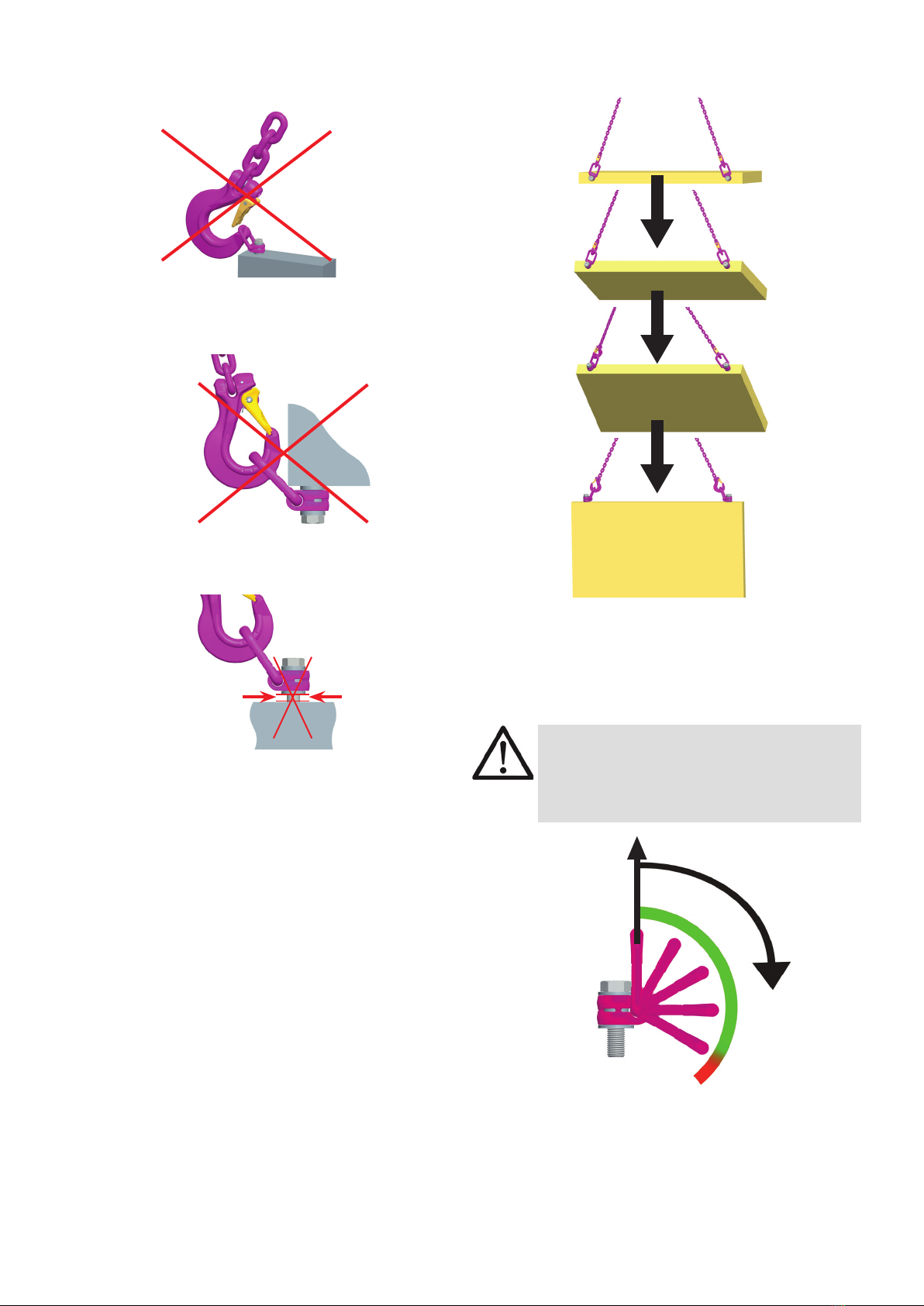
• When attaching and removing the lifting means (e.g.
lifting chains), crushing, shearing, trapping and impact
spots must be prevented.
• Prevent damage being caused to the lifting means by
loading at sharp edged.
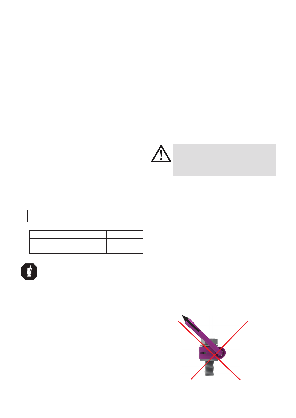
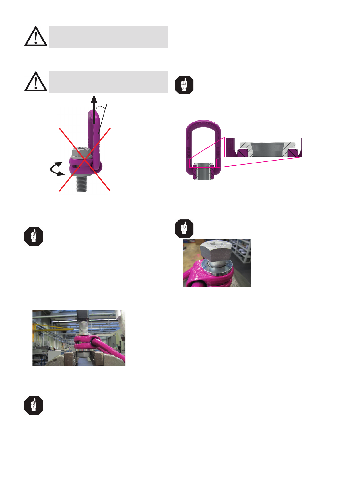
• Set the suspension ring of the VLBG-PLUS in the
direction of force before attaching the lifting means.
F
Pic. 1: Forbidden loading direction
3.2 Hints for the assembly
Basically essential:
• The material construction to which the lifting point
will be attached should be of adequate strength
to withstand forces during lifting without deforma-
tion. The German testing authority BG, recom-
mends the following minimum for bolt lengths:
1 x M in steel (minimum quality S235JR [1.0037])
1,25 x M in cast iron (for example GG 25)
2 x M in aluminium alloys
2.5 x M in aluminium-magnesium alloys
(M = diameter of RUD lifting point bolt, for ex. M 20)
• When lifting light metals, nonferrous heavy metals and
gray cast iron the thread has to be chosen in such a
way that the working load limit of the thread corre-
sponds to the requirements of the respective base
material.
• The lifting points must be positioned on the load in
such a way that movement is avoided during lifting:
• For single leg lifts, the load ring should be
vertically above the centre of gravity of the load.
• For two leg lifts, the lifting points must be
equidistant to/or above the centre of gravity of the load.
• For three and four leg lifts, the lifting points
should be arranged symmetrically around the
centre of gravity in the same plane, if possible.
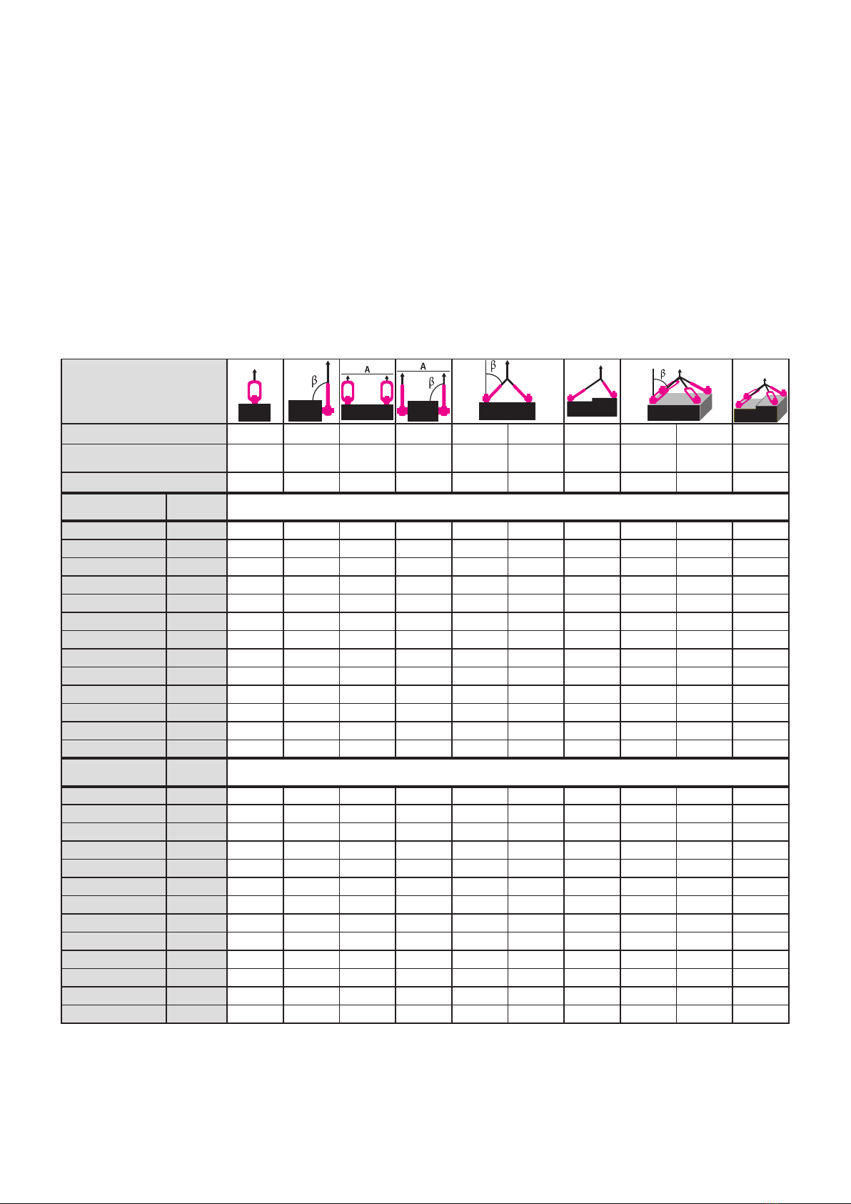
• Load symmetry:
The working load limit of individual RUD lifting points
are calculated using the following formula and are
based on symmetrical loading:
The calculation of load bearing legs is as follows:
Table 1: Load bearing strands (see table 2)
HINT
With unsymmetrical loads, the WLL of each Lift-
ing Point must be at least as high as the weight
of the load.
• A plane bolt-on surface (ØD, Tab. 3) with a perpendic-
ular thread hole must be guaranteed. The thread must
be carried out acc. to DIN 76 (countersink max. 1.05xd).
Tapped holes must be machined deep enough so that
the bearing surface of the lifting point will be supported.
• The VLBG-PLUS must be rotatable 360° when in-
stalled. Please observe the following:
• For a single use hand tightening with a spanner
is sufcient. Bolt supporting area must sit proper
on bolt-on surface.
• For long term application the VLBG-PLUS must
be tightened with torque according to table 3
(+/- 10%).
• When turning loads using the VLBG-PLUS (see
chapter 3.3.2 permissible lifting- and turning pro-
cess) it is necessary to tighten the bolt with a torque
(+/- 10%) acc. to table 3.
symmetrical asymmetrical
two leg 2 1
three / four leg 3 1
WLL = working load limit
G = load weight (kg)
n = number of load bearing legs
ß = angle of inclination of the chain to the vertical
WLL=G
n x cos ß

VLBG-PLUS4
3.3.2 Allowed lifting and turning operations
Pic. 5: Possible turning operation with the VLBG-PLUS
The following turning operations are allowed
• Turning operations where the load ring will be turned
into the load direction
WARNING
The load ring must not support itself at edges
or other attachments.
Also the attached lifting mean must not touch
the head of the bolt.
F
Pic. 6: Pivoting in load direction
• Turning operations where the VLBG-PLUS will be
turned around the bolt axle (exception: see chapter
3.3.3 Forbidden lifting and turning operations).
After a full turn by 180° the torque of the bolt must be
checked.
• Keep in mind that the lifting means in the VLBG-PLUS
must be freely movable.
Pic. 2: Use only suitable lifting means for hanging or
hooking into the VLBG-PLUS
• A bending load of the suspension ring is not permitted!
Pic. 3: The load must move freely and must not be loaded
at edges
• Always completely engage the lifting point.
Pic. 4: The lifting point must be completely screwed in.

5VLBG-PLUS
WARNING
Observe the requested torque value before
each lifting or turning operation.
3.3.3 Forbidden lifting and turning operations
The following operations are forbidden:
WARNING
The turning of the VLBG-PLUS under load in
the direction of the bolt axle (+15°) is forbidden.
F
15°
Pic. 7: Forbidden turning direction at loading in the
direction of the axle.
3.4 Dismantling / Assembling the RUD bolt
HINT
The dismantling / assembling and/or the ex-
change of the RUD bolt must only be executed
by a competent person!
3.4.1 Dismantling the bolt of the
VLBG-PLUS M8-M48
1. Position VLBG-PLUS with the thread end upwards
at the bushing on the top of the bench vice without
clamping the hexagon head of the bolt.
2. Slightly hit the bolt from the top to drive it out from the
bushing (Pic. 8).
Pic. 8: Dismantling position of the VLBG-PLUS
3.4.2 Assembling the bolt of the
VLBG-PLUS M8-M10
HINT
Only the appropriate strength class of bolt for
each specic size must be used!
M8-M10: ICE-Bolt only!
1. Insert the bolt into the drill hole in the socket until the
retaining ring is positioned on the socket
2. Squeeze the retaining ring together with at pliers so
that it sits deeply in the groove of the nut.
3. Now insert the bolt with light hits with a hammer fully
into the socket.
4. Finally, control the tightness of the bolt. The bolt must
be easily rotatable by 360°.
3.4.3 Assembling the bolt for
VLBG-PLUS M12-M48
HINT
Only the stated strength of class for the respec-
tive size of the bolts must be used!
M12-M24: ICE-Bolt | M27-M48: 10.9
1. Insert the bolt into the bushing at the tapered end,
where the chamfer is (refer to Pic. 9).
Pic. 9: VLBG-PLUS in sectional view.
The insertion chamfer is visible on top of the bushing
2. Insert the bolt into the socket in such a way that the
retaining ring is circumferential deepened in the socket
and seated (refer to Pic. 10).
TIP
Turn the bolt a few times under slight pressure
so that it is centered in the retaining ring!
Pic. 10: Retaining ring positioned as circumferential in the
recess
3. Use a light tap on the head of the bolt so that the bolt
can be assembled up to the end stop of the bolt head
on the socket.
4. Finally, control the tightness and seating of the bolt.
The bolt must be easily rotatable by 360°.
4 Inspection / repair
4.1 Hints for periodical inspections
The operator must determine and specify the nature
and scope of the required tests as well as the periods
of repeating tests by means of a risk assessment (see
sections 4.2 and 4.3).
The continuing suitability of the anchor point must be
checked at least 1x year by an expert.
Depending on the usage conditions, f.e. frequent usage,
increased wear or corrosion, it might be necessary to
check in shorter periods than one year. The inspection has
also to be carried out after accidents and special incidents.

VLBG-PLUS6
4.2 Test criteria for the regular visual inspection
by the user
• Correct bolt sizes and nut sizes, bolt quality and screw-
in lengths
• Always observe tightness of the bolts
––
> inspect the torque
• Comprehensiveness of the lifting point.
• Comprehensive, legible load-bearing information as
well as the manufacturer’s identication mark.
• Deformations on load-bearing parts such as basic
body, hanging or hooking in suspension ring and bolt
• Mechanical damage such as signicant notches, parti
cularly in areas subject to tensile stress.
• Easy rotation of the VLBG-PLUS must be ensured
4.3 Additional test criteria for the
competent person / repair worker
• Cross-section alterations caused by wear > 10%.
• Strong corrosion
• Cracks on load-bearing parts
• function of and damage to the bolts, nut as well a the
screw thread (disassembly / assembly of the bolt see
section 3.4).
• further checks may be required, depending on the
result of the risk assessment (e.g. testing for cracks
in load-bearing parts).
Method of lift
G
Number of legs 1 1 2 2 2 2 2 3 / 4 3 / 4 3 / 4
Angle of inclination <ß 0° 90° 0 ° 90° 0-45° >45-60° Un-
symm. 0-45° >45-60° Un-
symm.
factor 1 1 2 2 1,4 1 1 2,1 1,5 1
Type Thread WLL in tonnes, bolted and adjusted to the direction of pull
VLBG-PLUS 0.63t M 8 0.63 0.63 1.26 1.26 0.88 0.63 0.63 1.3 0.94 0.63
VLBG-PLUS 0.9t M 10 0.9 0.9 1.8 1.8 1.26 0.9 0.9 1.9 1.35 0.9
VLBG-PLUS 1.35t M 12 1.35 1.35 2.7 2.7 1.9 1.35 1.35 2.8 2 1.35
VLBG-PLUS 1.2t M 14 1.2 1.2 2.4 2.4 1.7 1.2 1.2 2.5 1.8 1.2
VLBG-PLUS 2t M 16 2 2 4 4 2.8 2 2 4.2 3 2
VLBG-PLUS 2t M 18 2 2 4 4 2.8 2 2 4.2 3 2
VLBG-PLUS 3.5t M 20 3.5 3.5 7 7 4.9 3.5 3.5 7.35 5.25 3.5
VLBG-PLUS 4.5t M 24 4.5 4.5 9 9 6.3 4.5 4.5 9.5 6.75 4.5
VLBG-PLUS 6.7t M 30 6.7 6.7 13.4 13.4 9.4 6.7 6.7 14 10 6.7
VLBG-PLUS 8t M 36 8 8 16 16 11.2 8 8 16.8 12 8
VLBG-PLUS 10t M 42 10 10 20 20 14 10 10 21 15 10
VLBG-PLUS 15t M 42 15 15 30 30 21 15 15 31.5 22.5 15
VLBG-PLUS 20t M 48 20 20 40 40 28 20 20 42 30 20
Type Thread WLL in lbs, bolted and adjusted to the direction of pull
VLBG-PLUS 0.63t M 8 1388 1388 2776 2776 1943 1388 1388 2914 2082 1388
VLBG-PLUS 0.9t M 10 1983 1983 3966 3966 2776 1983 1983 4161 2974 1983
VLBG-PLUS 1.35t M 12 2975 2975 5950 5950 4165 2975 2975 6247 4462 2975
VLBG-PLUS 1.2t M 14 2644 2644 5288 5288 3701 2644 2644 5552 5552 2644
VLBG-PLUS 2t M 16 4408 4408 8816 8816 6171 4408 4408 9256 9256 4408
VLBG-PLUS 2t M 18 4408 4408 8816 8816 6171 4408 4408 9256 6612 4408
VLBG-PLUS 3.5t M 20 7714 7714 15428 15428 10799 7714 7714 16199 11571 7714
VLBG-PLUS 4.5t M 24 9918 9918 19836 19836 13885 9918 9918 20827 14877 9918
VLBG-PLUS 6.7t M 30 14766 14766 29532 29532 20672 14766 14766 31008 22149 14766
VLBG-PLUS 8t M 36 17632 17632 35264 35264 24684 17632 17632 37027 26448 17632
VLBG-PLUS 10t M 42 22040 22040 44080 44080 30856 22040 22040 46284 33060 22040
VLBG-PLUS 15t M 42 33060 33060 66120 66120 46284 33060 33060 69426 49590 33060
VLBG-PLUS 20t M 48 44080 44080 88160 88160 61712 44080 44080 92568 66120 44080
Table 2: WLL in tons (above / top) and in lbs (below / bottom)
G
G
G
G
G
G
G

7VLBG-PLUS
B
C
M
A
D
HG
L
T
E
F
K
J
N
max.
max.
D
G
T
F
E
H
L
Table 3: Dimensioning Subject to technical modications
SW = wrench size
ISK = internal hexagon /
* from L=351 mm without internal hexagon
Type WLL
[t]
weight
[kg]
A
[mm]
B
[mm]
C
[mm]
D
[mm]
E
[mm]
F
[mm]
G
[mm]
H
stand
[mm]
H
max
[mm]
J
[mm]
K
[mm]
L
Stand
[mm]
L
max
[mm]
M N
[mm]
SW ISK T
[mm]
torque Art.-No.
Standard Vario
VLBG-PLUS 0.63t M8 0.63 0.3 30 52 34 24 40 10 29 11 76 75 45 40 105 8 32 13 5 75 30 Nm 8504651 8600470
VLBG-PLUS 0.9t M10 0.9 0.31 30 52 34 24 39 10 29 15 96 75 45 44 125 10 32 17 6 75 60 Nm 8504652 8600471
VLBG-PLUS 1.35t M12 1.35 0.34 32 52 34 26 38 10 29 18 116 75 45 47 145 12 32 19 8 75 150 Nm 8504653 8600472
VLBG-PLUS 1.2t M14 1.2 0.5 34.5 56 38 30 39 13.5 36 24 34 86 47 60 70 14 38 24 10 85 150 Nm 8504654 8600473
VLBG-PLUS 2t M16 2 0.55 34.5 56 38 30 39 13.5 36 22 149 86 47 58 185 16 38 24 10 85 150 Nm 8504655 8600474
VLBG-PLUS 2t M18 2 1.3 50 82 54 45 55 17 43 37 222 113 64 80 90 18 48 30 12 110 200 Nm 8504656 8600475
VLBG-PLUS 3.5t M20 3.5 1.3 50 82 54 45 55 17 43 32 187 113 64 75 230 20 48 30 12 110 400 Nm 8504657 8600476
VLBG-PLUS 4.5t M24 4.5 1.4 50 82 54 45 67 17 43 37 222 130 78 80 265 24 48 36 14 125 760 Nm 8504659 8600478
VLBG-PLUS 6.7t M30 6.7 3.2 60 103 65 60 67 22.5 61 49 279 151 80 110 340 30 67 46 17 147 1000 Nm 8504661 8600480
VLBG-PLUS 8t M36 8 6.2 77 122 82 70 97 26.5 77 63 223 205 113 140 300 36 79 55 22 196 800 Nm 7983553 8600289
VLBG-PLUS 10t M42 10 6.7 77 122 82 70 94 26.5 77 73 273 205 113 150 350 42 79 65 24 196 1000 Nm 7983554 8600290
VLBG-PLUS 15t M42 15 10.9 95 156 100 85 109 36 87 63 413 230 130 150 500 42 100 65 24* 222 1500 Nm 7982966 8600291
VLBG-PLUS 20t M48 20 11.6 95 156 100 95 105 36 87 73 303 230 130 160 350 48 100 75 27 222 2000 Nm 7982967 8600292
Other manuals for VLBG-PLUS
1
This manual suits for next models
25
Table of contents
Other RUD Safety Equipment manuals