RUD B-ABA Series Installation instructions

1
B-ABA
RUD Ketten
Rieger & Dietz GmbH u. Co. KG
73428 Aalen
Tel. +49 7361 504-1370
Fax +49 7361 504-1171
www.rud.com
RUD-Art.-Nr.: 7906416-EN / 02.020
Lifting Point
loadable from any side
> B-ABA <
Safety instructions
This safety instruction/declaration has to be kept on le
for the whole lifetime of the product.
Translation of the original safety instruction
EN
B-ABA
EG-Konformitätserklärung
entsprechend der EG-Maschinenrichtlinie 2006/42/EG, Anhang II A und ihren Änderungen
Hersteller:
RUD Ketten
Rieger & Dietz GmbH u. Co. KG
Friedensinsel
73432 Aalen
Hiermit erklären wir, dass die nachfolgend bezeichnete Maschine aufgrund ihrer Konzipie-
rung und Bauart, sowie in der von uns in Verkehr gebrachten Ausführung, den grundle-
genden Sicherheits- und Gesundheitsanforderungen der EG-Maschinenrichtlinie
2006/42/EG sowie den unten aufgeführten harmonisierten und nationalen Normen sowie
technischen Spezifikationen entspricht.
Bei einer nicht mit uns abgestimmten Änderung der Maschine verliert diese Erklärung ihre
Gültigkeit.
Produktbezeichnung: Anschraubpunkt starr
_____________________________________________
B-ABA
_____________________________________________
Folgende harmonisierten Normen wurden angewandt:
DIN EN 1677-1 : 2009-03 DIN EN ISO 12100 : 2011-03
_________________ _________________
_________________ _________________
_________________ _________________
_________________ _________________
_________________ _________________
Folgende nationalen Normen und technische Spezifikationen wurden außerdem angewandt:
BGR 500, KAP2.8 : 2008-04
_________________ _________________
_________________ _________________
_________________ _________________
_________________ _________________
_________________ _________________
Für die Zusammenstellung der Konformitätsdokumentation bevollmächtigte Person:
Michael Betzler, RUD Ketten, 73432 Aalen
Aalen, den 22.09.2016
Dr.-Ing. Arne Kriegsmann,(Prokurist/QMB)
_____________________________________________
Name, Funktion und Unterschrift Verantwortlicher
EC-Declaration of conformity
According to the EC-Machinery Directive 2006/42/EC, annex II A and amendments
Manufacturer:
RUD Ketten
Rieger & Dietz GmbH u. Co. KG
Friedensinsel
73432 Aalen
We hereby declare that the equipment sold by us because of its design and construction,
as mentioned below, corresponds to the appropriate, basic requirements of safety and
health of the corresponding EC-Machinery Directive 2006/42/EC as well as to the below
mentioned harmonized and national norms as well as technical specifications.
In case of any modification of the equipment, not being agreed upon with us, this declara-
tion becomes invalid.
Product name:
Lifting point rigid
_____________________________________________
B-ABA
_____________________________________________
The following harmonized norms were applied:
DIN EN 1677-1 : 2009-03 DIN EN ISO 12100 : 2011-03
_________________ _________________
_________________ _________________
_________________ _________________
_________________ _________________
_________________ _________________
The following national norms and technical specifications were applied:
BGR 500, KAP2.8 : 2008-04
_________________ _________________
_________________ _________________
_________________ _________________
_________________ _________________
_________________ _________________
Authorized person for the configuration of the declaration documents:
Michael Betzler, RUD Ketten, 73432 Aalen
Aalen, den 22.09.2016 Dr.-Ing. Arne Kriegsmann,(Prokurist/QMB)
_____________________________________________
Name, function and signature of the responsible person

2B-ABA
Before initial usage of the RUD lifting point
B-ABA, please read carefully the safety
instructions. Make sure that you have un-
derstood all subjected matters.
Non-observance can lead to serious per-
sonal injuries and material damage and
eliminates warranty.
1 Safety instructions
ATTENTION
Wrong assembled or damaged lifting points
B-ABA as well as improper use can lead to
injuries of persons and damage of objects
when load drops.
Please inspect all lifting points before each
use.
• Remove all body parts (fingers, hands, arms,
etc.) out of the hazard area (danger of crushing or
squeezing) during the lifting process.
• RUD lifting points B-ABA must only be used by in-
structed and competent persons considering BGR
500 (DGUV-rules 100-500) and outside Germany
noticing the country specic statutory regulations.
• No technical alterations must be implemented on
the B-ABA.
• No people may stay in the danger zone.
• Jerky lifting (strong impacts) should be prevented.
• Always ensure a stable position of the load when
lifting. Swinging must be prevented.
• Damaged or worn B-ABA must never be utilised.
2 Intended use of the B-ABA
RUD lifting points B-ABA must only be used for the
assembly at the load or at lifting means.
They are intended to be hinged into lifting means.
RUD lifting points B-ABA can also be used as lashing
points to attach lashing means.
Loading from any side is permitted.
RUD lifting points B-ABA must only be used in the
hereby described operation purpose.
3 Assembly- and instruction manual
3.1 General information
• Capability of temperature usage:
When used at higher temperatures the working
load limit (WLL) of the lifting point must be redu-
ced as follows:
- -40°C up to 200°C no reduction
- 200°C up to 300°C minus 10 %
- 300°C up to 400°C minus 25 %
Temperatures exceeding 400°C are prohibited!
• RUD lifting points B-ABA must not be used with
aggressive chemicals such as acids, alkaline so-
lutions and their vapours.
• Please mark mounting position of lifting point with
a coloured contrast paint for better visibility.
3.2 Hints for the assembly
Basically essential:
• The material construction to which the lifting point
will be attached should be of adequate strength to
withstand forces during lifting without deformation.
The German testing authority BG/DGUV, recom-
mends the following minimum for bolt lengths:
1x M in steel (minimum quality S235JR[1.0037])
1.25x M in cast iron (however when castings of
lower strength [<200 MPa] are used the
thread engagement has to be at least 1,5xd)
2x M in aluminum alloys
2.5x M in light metals of low strength
(M = thread size, e.g. M20)
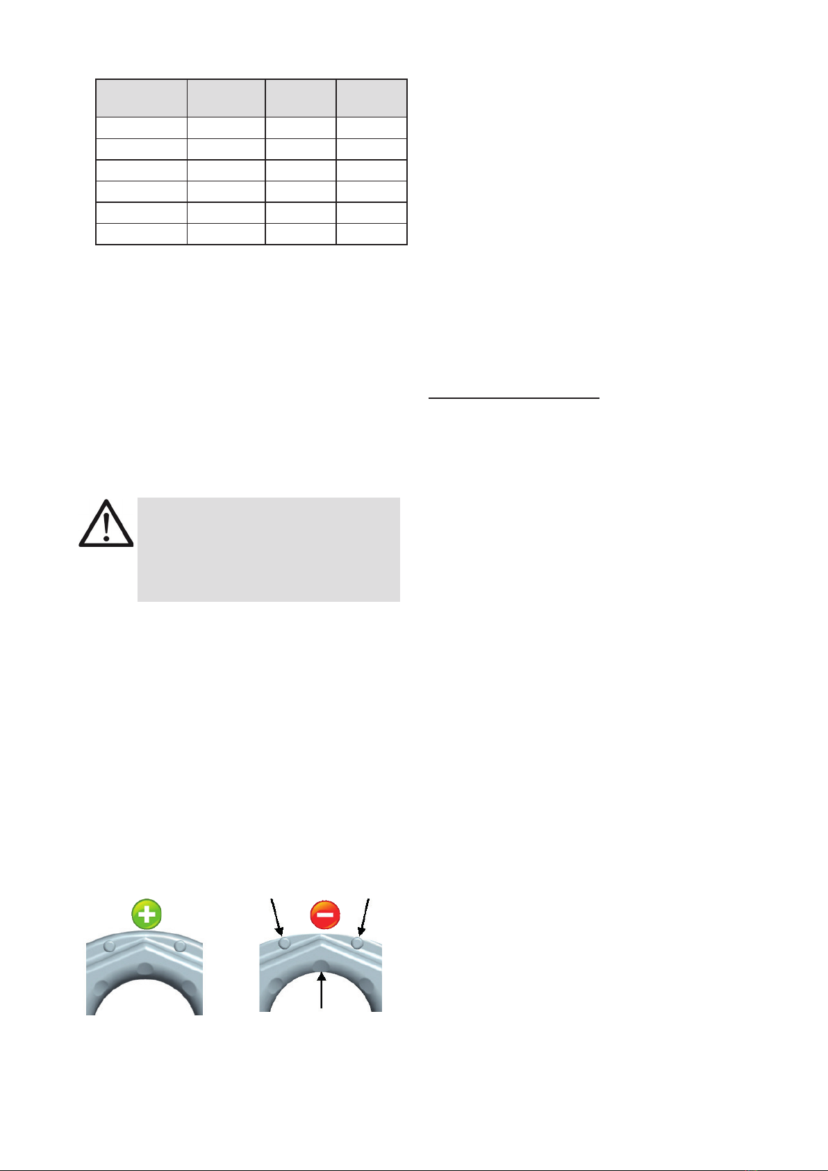
• The position of the lifting points must be carried
out in such a way that unintended movement like
turning or ipping will be avoided:
• For single leg lifts: the lifting point should be
vertically above the centre of gravity of the load.
• For two leg lifts: the lifting points must be
equidistant to/or above the centre of gravity
of the load.
• For three and four leg lifts. the lifting points
should be arranged symmetrical around the
centre of gravity, in the same plane if possible.
• Symmetry of loading:
Determine the necessary WLL of each lifting point
for a symmetrical or an unsymmetrical load by
using the following physical calculation formula:
WLL = necessary WLL (kg) of lifting point /
single strand (kg)
G = weight of load (kg)
n = number of load bearing strands
ß = Inclination angle of single strand
WLL=G
n x cos ß
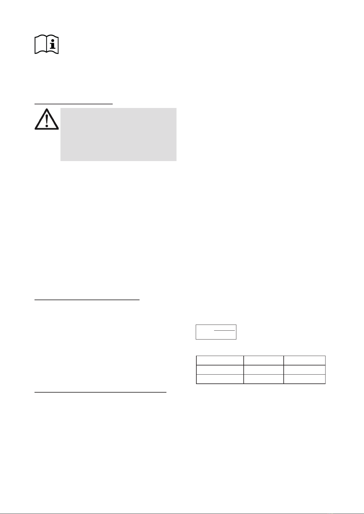
Number of load bearing strands:
symmetric unsymmetric
two leg 2 1
three / four leg 3 1
Table 1: Load bearing strands (compare to table 3)
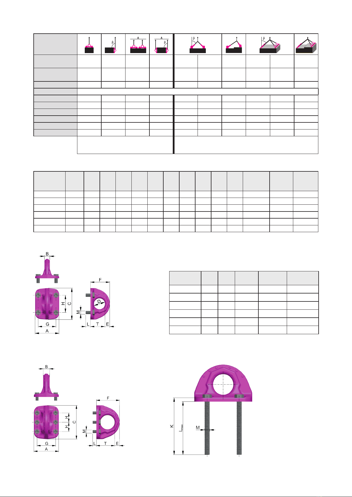
• RUD lifting points B-ABA must be installed by using
the supplied ICE-bolts.
If needed, Vario-ICE-bolts can be ordered on re-
quest (compare chart 5 / pic. 4).
• A plane bolt-on surface must be ensured resp.
provided. Blind holes must be drilled deep enough,
that the supporting area of the B-ABA ts properly.
Tighten bolts with required torque value (see table
2).

3
B-ABA
Type torque
[Nm]
thread d wrench
size SW
B-ABA 1.6 t 55 M10 16
B-ABA 3.2 t 100 M12 18
B-ABA 5 t 240 M16 24
B-ABA 10 t 450 M20 30
B-ABA 20 t 800 M24 36
B-ABA 31.5 t 950 M30 46
Table 2
• For a single use hand tightening with a spanner is
suciant. Bolt supporting area must sitproper on
bolt-on surface.
• Check nally the correct assembly (see chapter 4,
Inspection / repair).
3.3 User instructions
• Always regularly observe the appearance of the
whole lifting point (e.g. xed lifting point/slings)
before using it (secured bolt seat, strong corrosion,
cracks on load-bearing parts, deformations). Refer
to chapter 4 Inspection / repair.
ATTENTION
Wrong assembled or damaged B-ABA as
well as improper use can lead to injuries of
persons and damage of objects when load
drops. Please inspect all B-ABA before
each use.
• RUD components are designed according to DIN
EN 818 and DIN EN 1677 for a dynamic load of
20,000 load cycles.
• Keep in mind that several load cycles can occur
with a lifting procedure
• Keep in mind that, due to the high dynamic stress
with high numbers of load cycles, that there is a
danger that the product will be damaged
• The BG/DGUV recommends: For higher dy-
namic loading with a high number of load cycles
(continuous operation), the working load stress
must be reduced according to the driving mecha-
nism group 1Bm (M3 in accordance with DIN EN
818-7). Use a lifting point with a higher working
load limit.
• Please check carefully the wear indicator markings
of the lifting point (see picture 1):
Usage permitted:
no wear marks visible
Use prohibited:
Replacement criteria rea-
ched. Material all the way
down to the wear lenses
has gone
Pic. 1: Wear indicators
• To prevent unintended dismounting through shock
loading, rotation or vibration, thread locking uid such
as Loctite (depending on the application, please pay
attention to the manufacturer‘s instruction) could be
used to secure the bolt, or use form-closed devices.
• Please note that the lifting mean must be free mo-
veable within the lifting point B-ABA. When lifting
means (sling chains) are hinged or unhinged, no
pinching, shearing or joint spots must occure during
the handling.
• Avoid damage of lifting means resulting from sharp
edges.
• If the lifting point B-ABA is used solely for lashing,
the value of the working load limit can be doubled:
LC = 2 x WLL
4 Inspection / repair
4.1 Hints for periodical inspections
The operator must determine and specify the nature
and scope of the required tests as well as the periods
of repeating tests by means of a risk assessment (see
sections 4.2 and 4.3).
The continuing suitability of the anchor point must be
checked at least 1x year by an expert.
Depending on the usage conditions, f.e. frequent
usage, increased wear or corrosion, it might be nec-
essary to check in shorter periods than one year. The
inspection has also to be carried out after accidents
and special incidents.
4.2 Test criteria for the regular visual inspection
by the user
• Ensure correct bolt and nut size, quality and length
• Ensure compatibility of bolt thread and tapped hole
––
> inspect the torque
• Completeness of the lifting point.
• Complete, readable WLL statements as well as
manufacturer sign
• Deformation at load bearing components like base
body and bolts
• Mechanical damage such as signicant notches,
particularly in areas subject to tensile stress.
4.3 Additional test criteria for the
competent person / repair worker
• Reduction of cross-section due to wear >10 %
(see picture 1, wear indicators)
• Strong corrosion
• Function and damage at the bolt, nut and/or
thread.
• further checks may be required, depending on
the result of the risk assessment (e.g. testing for
cracks in load-bearing parts).

4B-ABA
Method of lift
G
G
G
G
G
G
G
G
number of legs 1 1 2 2 2 2 2 3/4 3/4 3/4
Angle of inclination 0°-7° 90° 0°-7° 90° 0-45° 45°-60° Unsymm. 0-45° 45°-60° Unsymm.
Factor 1 1 2 2 1.4 1 1 2.1 1.5 1
Type For the max. total load weight >G< in metric tons [t]
B-ABA 1.6 t 1.6 1.6 3.2 3.2 2.2 1.6 1.6 3.4 2.4 1.6
B-ABA 3.2 t 3.2 3.2 6.4 6.4 4.5 3.2 3.2 6.8 4.8 3.2
B-ABA 5 t 5.0 5.0 10 10 7.1 5 5 10.6 7.5 5
B-ABA 10 t 10.0 10.0 20 20 14.1 10 10 21.2 15 10
B-ABA 20 t 20.0 20.0 40 40 28 20 20 42 30 20
B-ABA 31.5 t 31.5 31.5 63 63 45 31.5 31.5 67 47.5 31.5
At a lift with one strand and two parallel strands
where the inclination angles are at the max. ± 7°,
the lifting methode can be assumed as a vertical lift.
When lifting with two, three or four leg lifting means, inclination angles of
less than 15° shall be avoided, if possible (Risk of instability).
Table 3: WLL in [t]
Table 4: Dimensioning Subject to technical alterations.
Pic. 2: Dimensioning B-ABA 1.6 t - 10 t
Type WLL
Lifting
[t]
A
[mm]
B
[mm]
C
[mm]
D
[mm]
E
[mm]
F
[mm]
G
[mm]
H
[mm]
T
[mm]
L
[mm]
M weight
[kg/pc.]
Ref.-No.
B-ABA 1.6 t 1.6 75 16 100 35 16 62.5 55 55 46.5 13 4 x M10 0.9 7906266
B-ABA 3.2 t 3.2 92 23 137 50 21 86 70 75 65 16 4 x M12 2.0 7906267
B-ABA 5 t 5.0 113 27 172 60 28 108 84 95 80 24 4 x M16 4.1 7906268
B-ABA 10 t 10.0 146 38 228 80 36 141 110 125 105 25 4 x M20 9.3 7906269
B-ABA 20 t 20.0 200 52 272 115 40 188 150 75 148 30 6 x M24 18.8 7906270
B-ABA 31.5 t 31.5 230 64 320 130 50 215 175 87.5 165 40 6 x M30 29.5 7906271
Pic. 3: Dimensioning B-ABA 20 t - 31.5 t Pic. 4: B-ABA bolt length
Type K
[mm]
Lmax
[mm]
M used bolt Ref.-No.
ICE-bolt
B-ABA 1.6 t 125 118 4 x M10 M10 x 125 7905920
B-ABA 3.2 t 145 136 4 x M12 M12 x 145 7905921
B-ABA 5 t 185 174 4 x M16 M16 x 185 7908216
B-ABA 10 t 230 215 4 x M20 M20 x 230 7908217
B-ABA 20 t 265 245 6 x M24 M24 x 265 7908218
B-ABA 31.5 t 340 320 6 x M30 M30 x 340 7908418
Table 5: Vario-ICE-bolts (thread all the way up to the head)
This manual suits for next models
12
Other RUD TV Mount manuals