VWBG2
Before initial usage of the RUD VWBG
hoist rings please read carefully the safety
instructions. Make sure that you have un-
derstood all subjected matters.
Non-observance can lead to serious per-
sonal injuries and material damage and
eliminates warranty
1 Safety instructions
ATTENTION
Wrong assembled or damaged lifting points as
well as improper use can lead to injuries of per-
sons and damage of objects when load drops.
Please inspect all lifting points before each use.
• Remove all body parts (ngers, hands, arms, etc.) out
of the hazard area (danger of crushing or squeezing)
during the lifting process.
• RUD VWBG lifting points must only be used by instruc-
ted and competent persons considering DGUV 100-500
(BGR 500) and outside Germany noticing the country
specic statutory regulations.
• Do not exceed the working load limit (WLL) indicated
on the lifting point (except when used at straight lift and
with an optimized suspension link position - see Pic. 1
and table 3).
• A permanent turning action under load is not permissable.
RUD hoist rings VWBG are rotable 90° to the bolt-on
direction with the nominal working load limit.
• The load ring must not be bend.
• Ball bearing must not be disassembled.
• No technical alterations must be implemented on the
VWBG.
• No people may stay in the danger zone.
• Jerky lifting (strong impacts) should be prevented.
• Always ensure a stable position of the load when lifting.
Swinging must be prevented.
• Damaged or worn VWBG must never be utilised.
2 Intended use of VWBG
RUD VWBG lifting points must only be used for the assem-
bly at the load or at lifting means.
They are intended to be hinged into lifting means. RUD
hoist rings VWBG are rotable 90° to the bolt-on direction
with the nominal working load limit. A permanent turning
action under load is not permissable.
RUD VWBG lifting points can also be used as lashing points
to attach lashing means.
RUD VWGB lifting points must only be used in the hereby
described operation purpose.
3 Assembly- and instruction manual
3.1 General information
• Capability of temperature usage:
Usage at higher temperatures is not recommended due
to the grease lling in the ball bearing.
Should this though be necessary, the working load limit
(WLL) of the VWBG must be reduced as follows:
- -40°C up to 200°C no reduction
- 200°C up to 300°C minus 10 %
- 300°C up to 400°C minus 25 %
- Temperatures exceeding 400°C are prohibited!
Please pay attention when using DIN EN 7042 (DIN
980) nuts the max. operation temperature of 150°C
(acc. to DIN EN ISO 2320).
• RUD VWBG lifting points must not be used with aggres-
sive chemicals such as acids, alkaline solutions and their
vapours.
• Please mark mounting position of lifting point with a
coloured contrast paint for better visibility.
3.2 Hints for the assembly
Basically essential:
• The material construction to which the lifting point will
be attached should be of adequate strength to withstand
forces during lifting without deformation. The German
testing authority BG, recommends the following minimum
for the bolt lengths:
- 1 x M (thread diameter) in steel
(min. quality 235JR [1.0037])
- 1.25 x M (thread diameter) in cast iron
(e.g. GG 25)
- 2 x M (thread diameter) in aluminium
- 2.5 x M (thread diameter) in light alloys of low
strength (M = thread size/diameter, e.g. M20)
• When lifting light metals, nonferrous metals and gray
cast iron the thread has to be chosen in such a way that
the WLL of the thread corresponds to the requirements
of the base material.
• The position of the lifting points must be carried out in
such a way that unintended movement like turning or
ipping will be avoided.
• For single leg lifts, the lifting point should be verti-
cally above the centre of gravity of the load.
• For two leg lifts, the lifting points must be equidi-
stant to or above the centre of gravity of the load.
• For three and four leg lifts, the lifting points
should be arranged symmetrical around the cen-
tre of gravity, in the same plane if possible.
• Load symmetry:
Determine the necessary WLL of each lifting point for
a symmetrical or an unsymmetrical load by using the
following physical calculation formula:
WLL = necessary WLL of lifting point / single strand
G = weight of load
n = number of load bearing strands
ß = inclination angle of single strand
G
n x cos ß
WLL=
Number of load bearing strands:
Symmetric Unsymmetric
two leg 2 1
three / four leg 3 1
Table 1: Load bearing strands
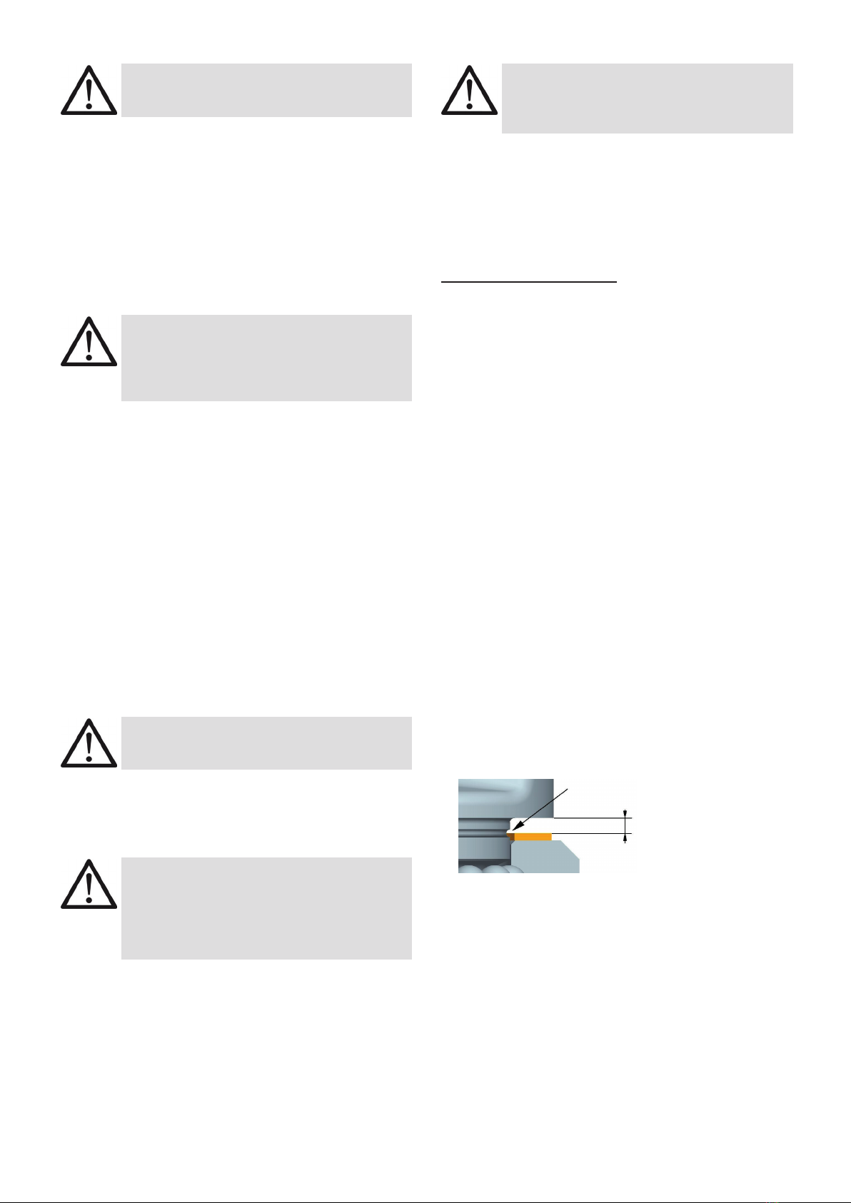
• A plane bolt-on surface (ØD) with a perpendicular th-
read hole must be guaranteed. The countersink of the
thread hole must be = nominal thread diameter plus
4 mm (RUD Lifting Points VLBG, VRS and PP each larger
than M30, can be installed into these tapped holes)
• Tapped holes must be machined deep enough so that
the bearing surface of the lifting point will be supported.
Machine through holes up to DIN EN 20273-middle.
• Due to the ball bearing it is sucient for a single lift to
tighten the VWBG until the bearing surface has support
by using a spanner acc. to DIN 895 resp. DIN 894, wit-
hout using an extension. If the VWBG shall permanently
installed at the load, tensioning must be carried out with
a torque (+/- 10 %) according to table 2.
• The type VWBG can be supplied with dierent thread
lengths (see Fvario in chart 2), and the metric versions
with washer und crack detected nut.