3
VVS/RS-VVS
VVS/RS-VVS 6
3.3 Sequence of assembly
In the following description the assembly of the con-
necting link will be described exemplarily with the
example of a masterlink and an VIP chain.
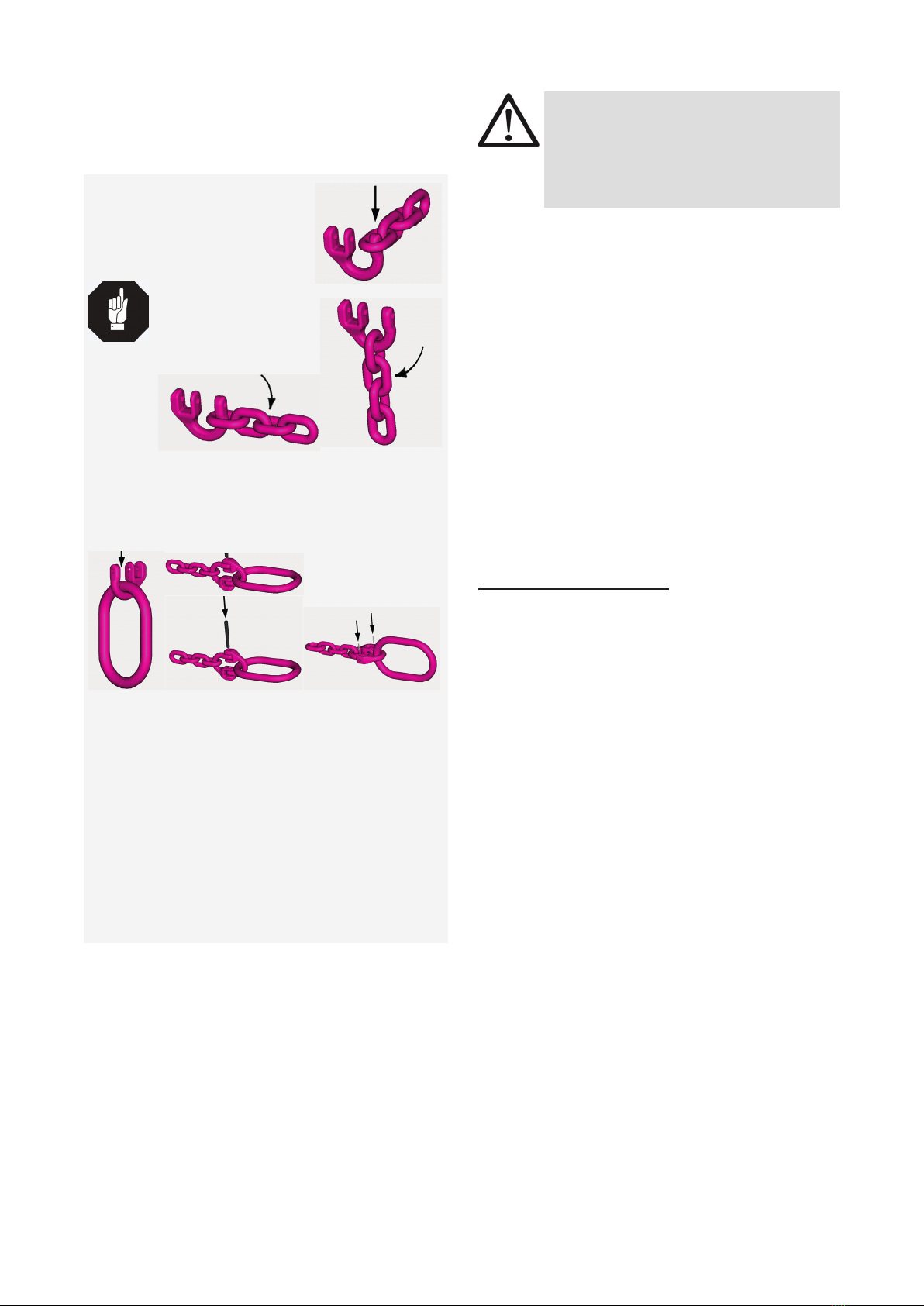
1. Install last chain link into the single
bow eye (Pic. 4).
In this case there is no addi-
tional connector necessary.
HINT
At the beginning of the
bow rounding, chain link
can be turned by 90°
within the bow (Pic. 5).
Pic. 5 Pic. 6
2. Position chain strand to the bottom of the bow part
(Pic. 6).
3. Put into the second bow part a desired connecting
part, f.e. a masterlink (Pic. 7).
Pic. 7 Pic. 8 / 9 Pic. 10
4. Assemble both bow parts together in such a way
that components are aligned (Pic. 8).
5. Install pin into the bore of the eye (Pic. 9). Both
bow parts are now connected with each other.
6. Secure the assembled connecting link as follows
(Pic. 10):
- Position both securing pins/sleeve pins in
such a way, that the slot faces the outside.
- Knock both sleeve pins in with a hammer.
7. Finally Check the correct assembly (see chapter
4 Inspection / repair).
3.4 User instructions
• Check before each loading of the connecting link,
that connecting pin is installed correct in the bow
eye. Secure pin by hammering the sleeve pins in.
• Make sure that the load force happens in the straight
leg without being twisted, fold-over or kinked.
• Always regularly observe the appearance of the
whole lifting mean (e.g. by the person responsible
für attachment) before using it (strong corrosion,
wear, cracks on load-bearing parts, deformations).
Refer to chapter 4 Inspection / repair.
ATTENTION
Wrong assembled or damaged lifting and
lashing means as well as improper use can
lead to injuries of persons and damage of ob-
jects when load drops down. Please inspect
all lifting and lashing means before each use.
• RUD components are designed according to DIN
EN 818 and DIN EN 1677 for a dynamic load of
20,000 load cycles.
• Keep in mind that several load cycles can
occur with a lifting procedure.
• Keep in mind that, due to the high dynamic stress
with high numbers of load cycles, that there is a
danger that the product will be damaged
• The BG/DGUV recommends: For higher dynamic
loading with a high number of load cycles (contin-
uous operation), the working load stress must be
reduced according to the driving mechanism group
1Bm (M3 in accordance with DIN EN 818-7). Use
a lifting mean with a higher working load limit.
• Leave hazardous area when possible.
• Watch always attached loads.
• Read for all lifting means the RUD sling chain Sa-
fety instructions for RUD lifting means.
4 Inspection / repair
4.1 Hints for periodical inspections
The operator must determine and specify the nature
and scope of the required tests as well as the periods
of repeating tests by means of a risk assessment (see
sections 4.2 and 4.3).
The continuing suitability of the lifting mean must be
checked at least 1x year by an expert.
Depending on the usage conditions, f.e. frequent usage,
increased wear or corrosion, it might be necessary to
check in shorter periods than one year. The inspection
has also to be carried out after accidents and special
incidents. The operator must specify the test cycles.
4.2 Test criteria for the regular visual inspection
by the user
• Completeness of the VIP Connecting link
• Complete readable size and manufacturer sign
• Deformations on load-bearing parts
• Mechanical damage like strong notches, especially
in areas where tensile stress occurs
4.3 Additional test criteria for the
competent person / repair worker
• Damaging and reduction of cross section caused
by wear > 10 %, especially at connecting pins and
at the eyes of the VVS bows.
• Strong corrosion
• further checks may be required, depending on the
result of the risk assessment (e.g. testing for cracks
in load-bearing parts).