WBPG2
Please read user instruction before initial opera-
tion of the Hoist ring boltable on plate (WBPG).
Make sure that you have comprehended all
subjected matters.
Non observance can lead to serious personal
injuries and material damage and eliminates
warranty.
1 Safety instructions
WARNUNG
Wrong assembled or damaged WBPG as well
as improper use can lead to injuries of persons
and damage of objects when load drops.
Please inspect all WBPG before each use.
• Remove all body parts (ngers, hands, arms, etc.) out
of the hazard area (danger of crushing or squeezing)
during the lifting process.
• The WBPG must be used only by authorised and
trained people in adherence to BGR/DGUV regulations
100-500, Chapter 2.8 and, outside Germany, when
observing the relevant specic national regulations.
• Do not exceed the working load limit (WLL) indicated
on the lifting point.
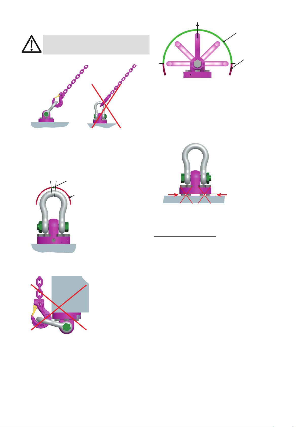
• WBPG must be able to pivot by 180° and should swivel
360°, in the tightened condition.
• No technical alterations must be implemented on the
WBPG.
• No people may stay in the danger zone.
• Jerky lifting (strong impacts) should be prevented.
• Always ensure a stable position of the load when lifting.
Swinging must be prevented.
• Damaged or worn WBPG must never be utilised.
2 Intended use
• WBPG must only be used for the assembly of the load
or at load accepting means
• Their usage is intended to be used as lifting means.
• WBPG lifting points are only suitable for loading in the
pivoting direction of the suspension ring.
• The WBPG can also be used as lashing points for the
xture of lashing means.
• The WBPG must only be used in the here described
usage purpose.
3 Assembly- and instruction manual
3.1 General information
• Eects of temperature:
WBPG hoist rings can be used in temperature areas from
-10°C up to 100°C
Temperatures above 100°C are not permitted!
• RUD-Lifting points must not be used under chemical in-
uences such as acids, alkaline solutions and vapours
e.g. in pickling baths or hot dip galvanising plants. If
this cannot avoided, please contact the manufacturer
indicating the concentration, period of penetration and
temperature of use.
• The places where the lifting points are xed should be
marked with colour.
• WPBG are supplied by RUD with crack detected
hexagon resp. cap screws:
WBPG 85 t - 120 t: 10.9 bolts
WBPG 150 t - 250 t: 12.9 bolts
ATTENTION
Use only the appropriate strength class of bolt, for
each specic size!
• Original bolts are available as a spare part from RUD.
• When using 10.9/12.9 bolts of the size M42-M48 from
other suppliers, make sure that they have been 100%
inspected in regards of cracks. A written conrmation
of the absence of cracks must be added to the doc-
umentation.
The middle notch toughness at the lowest approved
use temperature must be at least 36 J. This is required
for the test principles for GS OA 15-04 lifting points.
• If the WBPG is used exclusively for lashing, the
value of the working load limit can be doubled.
LC = permissible lashing capacity = 2 x WLL
HINT
If the WBPG is/was used as a lashing point,
with a force higher than the WLL, it must not
be used as a lifting point afterwards.
If the WBPG is/was used as a lashing point, up
to the WLL only, it can still be used afterwards
as a lifting point.
3.2 Hints for the assembly
Basically essential:
• The material construction to which the lifting point
will be attached should be of adequate strength
to withstand forces during lifting without deforma-
tion. The German testing authority BG, recom-
mends the following minimum for bolt lengths:
1 x M in steel (minimum quality S235JR [1.0037])
1.25 x M in cast iron (for example GG 25)
(M = diameter of RUD lifting point bolt, for ex. M 20)
• When lifting light metals, nonferrous heavy metals
and gray cast iron the thread has to be chosen in
such a way that the working load limit of the thread
corresponds to the requirements of the respective
base material.
• Determine the position of the lifting point in such a
way that prohibited loading, like bending forces at the
suspension ring or tip over of the load will be avoided.
• For single leg lifts:WBPG vertically above the
center of gravity of the load.
• For two leg lifts:the lifting points must be
equidistant to/or above the center of gravity of the load
• For three and four leg lifts:Positioning equally in
one level around the center of gravity (COG).
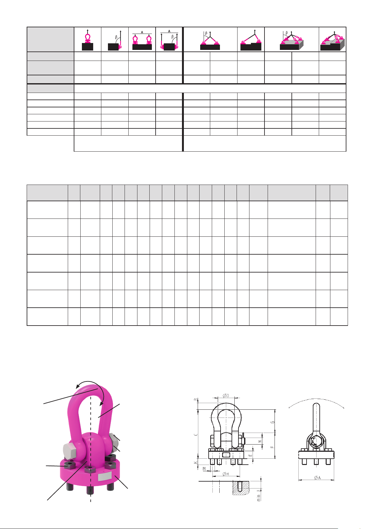
• Load symmetry:
Determine the required load-bearing capacity of the
individual lifting point for both symmetrical and asym-
metrical loading according to the physical relationship
described by the following formula: