2IVH / VVH
The present instruction is only valid for the follo-
wing variants of the shortening hook
• IVH ICE-Shortening hook in ICE-Pink (Purple colour,
quality grade 120, D1 stamping)
• VVH VIP-Shortening hook in VIP-Pink
(Magenta colour, quality grade 100, H1 stamping)
Please read assembly instruction carefully
before initial operation of the Shortening
hook. Make sure to understand all volumes.
Nonobservance of this assembly manual
can lead to serious physical injury and pro-
perty damage and eliminates warranty.
In doubt or in misconception please note
that the German version of this document
is decisive.
1 Safety instructions
ATTENTION
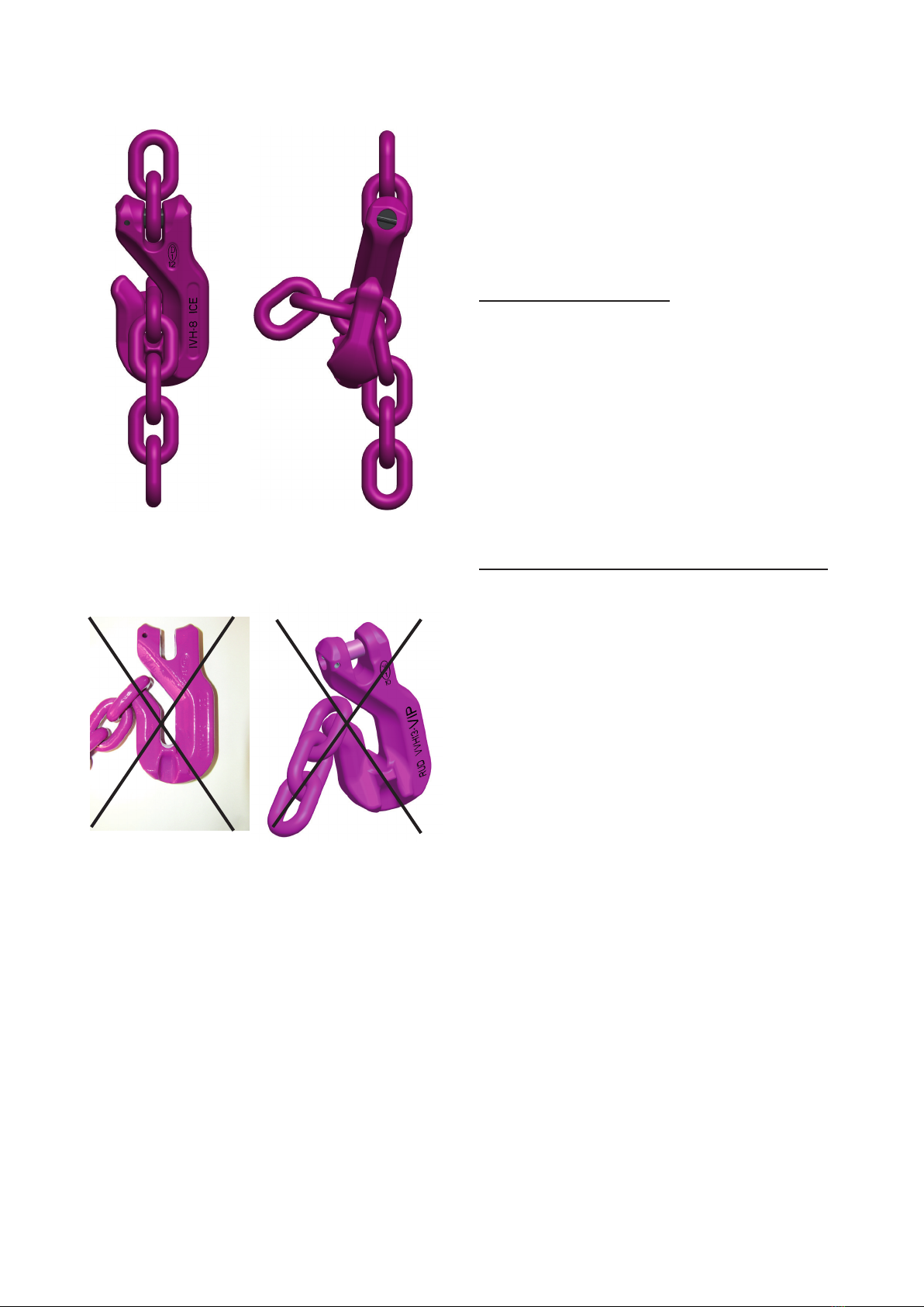
Wrong assembled or damaged lifting and
lashing means as well as improper use can
lead to injuries of persons and damage of
objects when load drops.
Please inspect all lifting points before each
use.
• Please consider extreme circumstances or shock
loading when choosing the used Shortening hook
and the components.
• Only RUD round steel link chains of the corres-
ponding nominal size must be attached to the
Shortening hook.
• RUD Shortening hook must only be used by instruc-
ted and competent persons considering DGUV
100-500, 2.8 (BGR 500) and outside Germany
noticing the country specic statutory regulations.
2 Intended use
Hereby described shortening hooks must only be used
for lifting, lashing or transporting of loads.
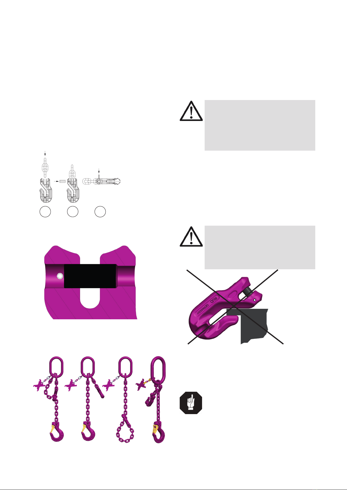
Please observe that the shortening hook/chain can
straighten out in the loading direction
Only RUD round steel link chains of the corresponding
nominal size must be attached to the shortening hook.
The shortening hooks are designed acc. to DIN 5692.
3 Assembly- and instruction manual
3.1 General information
• Capability of temperature usage ICE-components
(IVH): When using the ICE Shortening hook at
temperatures beyond 200°C the permissible WLL
has to be reduced.
-60°C up to 200°C no reduction
200°C up to 250°C minus 10 %
250°C up to 300°C minus 40 %
Temperatures exceeding 300°C are prohibited!
• Capability of temperature usage VIP-components
(VVH): When using the VIP Shortening hook at
temperatures beyond 200°C the permissible WLL
has to be reduced.
-40°C up to 200°C no reduction
200°C up to 300°C minus 10 %
300°C up to 380°C minus 40 %
Temperatures exceeding 380°C are prohibited!
• RUD VIP Shortening hooks must not be used with ag-
gressive chemicals such as acids, alkaline solutions
and their vapours.
• The WLL oft he components are depending on the
following variables:
- Quality grade of component (picture 1 to 3)
- Nominal size of component
- Present load factor
The permissible WLL can be taken out oft he
corresponding ICE- and VIP user instructions (or
alternatively from the website ww.rud.com).
3.2 Hints for the assembly
When assembling the shortening hook please observe
the correct dimensioning of chain and component. The
quality grade/nominal size can be recognized by the
stamping/marking at the component/pin/chain resp.
by the colour.
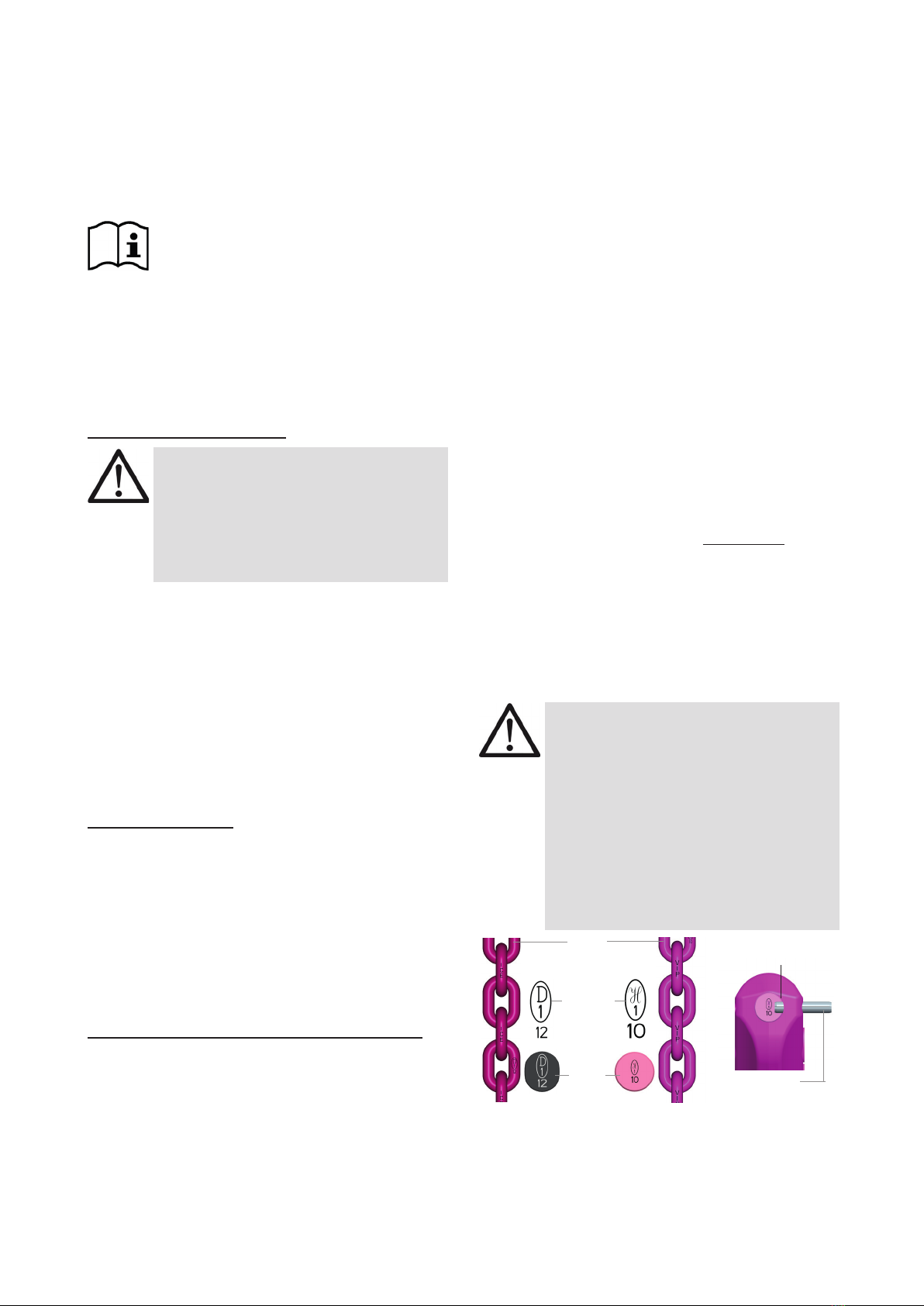
HINT
Observe in any case the quality grade
assignment at the components
- Please assemble only load pins with
D1-12 stamping into the ICE com-
ponents (IVH)
- Please assemble only load pins with
H1-10 stamping into the VIP
components (VVH)
Mixing of system components of dierent
quality grades/ nominal sizes is not allo-
wed.
chain
stam-
ping
load
pin
G-Pin
including stamping
sleeve pin
Pic. 1:
Quality Grade 120
ICE- chain,
stamping D1-12
Oval pin D1-12
Pic. 2:
Quality Grade 10
VIP- chain,
stamping H1-10
Round pin H1-10
Pic. 3:
VIP- G-pin
incl. VIP-
stamping +
sleeve pin