RUD VLBG-PLUS User manual

1VLBG-PLUS
Anschlagpunkte in ICE-Pink -
schraubbar
VLBG-PLUS
anneaux de levage à visser
en couleur ICE-rose
Load ring VLBG-PLUS
for bolting (ICE-PINK)
RUD Ketten
Rieger & Dietz GmbH u. Co. KG
73428 Aalen/Germany
Tel. +49 7361 504-1370
Fax +49 7361 504-1460
www.rud.com
RUD-Art.-Nr.: 7907302/08.016
Lastbock-Gewinde
>VLBG-PLUS<
Betriebsanleitung
Diese Betriebsanleitung/Herstellererklärung ist über die gesamte Nutz-
zeit aufzubewahren - Originalbetriebsanleitung -
Safety instructions
This safety instruction/declaration of the manufacturer has to be kept on
le for the whole lifetime of the product.
- Translation of the Original instructions -
Instructions pour la sécurité
Ces instructions pour la sécurité/déclaration de fabricant
doivent être conservées durant toute la période d’utilisation.
-Traduction du mode d’emploi original -
EG-Konformitätserklärung
entsprechend der EG-Maschinenrichtlinie 2006/42/EG, Anhang II A und ihren Änderungen
Hersteller:
RUD Ketten
Rieger & Dietz GmbH u. Co. KG
Friedensinsel
73432 Aalen
Hiermit erklären wir, dass die nachfolgend bezeichnete Maschine aufgrund ihrer Konzipie-
rung und Bauart, sowie in der von uns in Verkehr gebrachten Ausführung, den grundle-
genden Sicherheits- und Gesundheitsanforderungen der EG-Maschinenrichtlinie
2006/42/EG sowie den unten aufgeführten harmonisierten und nationalen Normen sowie
technischen Spezifikationen entspricht.
Bei einer nicht mit uns abgestimmten Änderung der Maschine verliert diese Erklärung ihre
Gültigkeit.
Produktbezeichnung: Lastbock VLBG-PLUS
_____________________________________________
_____________________________________________
Folgende harmonisierten Normen wurden angewandt:
DIN EN 1677-1 : 2009-03 DIN EN ISO 12100 : 2011-03
_________________ _________________
_________________ _________________
_________________ _________________
_________________ _________________
_________________ _________________
Folgende nationalen Normen und technische Spezifikationen wurden außerdem angewandt:
BGR 500, KAP2.8 : 2008-04
_________________ _________________
_________________ _________________
_________________ _________________
_________________ _________________
_________________ _________________
Für die Zusammenstellung der Konformitätsdokumentation bevollmächtigte Person:
Reinhard Smetz, RUD Ketten, 73432 Aalen
Aalen, den 12.05.2016
Dr.-Ing. Arne Kriegsmann,(Prokurist/QMB)
_____________________________________________
Name, Funktion und Unterschrift Verantwortlicher
EC-Declaration of conformity
According to the EC-Machinery Directive 2006/42/EC, annex II A and amendments
Manufacturer: RUD Ketten
Rieger & Dietz GmbH u. Co. KG
Friedensinsel
73432 Aalen
We hereby declare that the equipment sold by us because of its design and construction,
as mentioned below, corresponds to the appropriate, basic requirements of safety and
health of the corresponding EC-Machinery Directive 2006/42/EC as well as to the below
mentioned harmonized and national norms as well as technical specifications.
In case of any modification of the equipment, not being agreed upon with us, this declara-
tion becomes invalid.
Product name: Load ring VLBG-PLUS
_____________________________________________
_____________________________________________
The following harmonized norms were applied:
DIN EN 1677-1 : 2009-03 DIN EN ISO 12100 : 2011-03
_________________ _________________
_________________ _________________
_________________ _________________
_________________ _________________
_________________ _________________
The following national norms and technical specifications were applied:
BGR 500, KAP2.8 : 2008-04
_________________ _________________
_________________ _________________
_________________ _________________
_________________ _________________
_________________ _________________
Authorized person for the configuration of the declaration documents:
Reinhard Smetz, RUD Ketten, 73432 Aalen
Aalen, den 12.05.2016 Dr.-Ing. Arne Kriegsmann,(Prokurist/QMB)
_____________________________________________
Name, function and signature of the responsible person
DÉCLARATION CE DE CONFORMITÉ
Conformément à la directive machine 2006/42/CE, annexe II A et ses modifications
Fabriquant:
RUD Ketten
Rieger & Dietz GmbH u. Co. KG
Friedensinsel
73432 Aalen
Par la présente, nous déclarons que la machine indiquée ci-dessous, de part sa concep-
tion et type de construction, ainsi que la version que nous mettons surle marché, satisfait
à l'ensemble des dispositions pertinentes de la directive machine en 2006/42/CE, des nor-
mes harmonisées et nationales ainsi que des spécifications techniques ci dessous.
Tout modification de la machine sans notre consentement préalable entraine la nullité de
cette présente déclaration.
Désignation du produit : anneau décentré à étrier
_____________________________________________
VLBG-PLUS
_____________________________________________
En outre, les normes harmonisées suivantes ont étés appliquées :
DIN EN 1677-1 : 2009-03 DIN EN ISO 12100 : 2011-03
_________________ _________________
_________________ _________________
_________________ _________________
_________________ _________________
_________________ _________________
Les normes et spécifications techniques nationales suivantes ont étés appliquées :
BGR 500, KAP2.8 : 2008-04
_________________ _________________
_________________ _________________
_________________ _________________
_________________ _________________
_________________ _________________
Personne autorisée à constituer le dossier technique :
Reinhard Smetz, RUD Ketten, 73432 Aalen
Aalen, den 12.05.2016
Dr.-Ing. Arne Kriegsmann,(Prokurist/QMB)
_____________________________________________
Nom, fonction et signature du responsable
OA 1651053

VLBG-PLUS2
Lesen Sie vor dem Gebrauch der
schraubbaren Anschlagpunkte Last-
bock-Gewinde (nachfolgend VLBG-PLUS
genannt) die Betriebsanleitung gründlich
durch. Vergewissern Sie sich, dass Sie
alle Inhalte verstanden haben.
Eine Nichtbeachtung der Anweisun-
gen kann zu personellen und materi-
ellen Schäden führen und schließt die
Gewährleistung aus.
1 Sicherheitshinweise
WARNUNG
Falsch montierte oder beschädigte VLBG-PLUS
sowie unsachgemäßer Gebrauch können zu
Verletzungen von Personen und Schäden an
Gegenständen beim Absturz führen.
Kontrollieren Sie alle VLBG-PLUS sorgfältig vor
jedem Gebrauch.
• Die VLBG-PLUS dürfen nur durch beauftragte und un-
terwiesene Personen, unter Beachtung der BGR 500,
Kapitel 2.8 (DGUV- Regeln 100-500), und außerhalb
Deutschlands den entsprechenden landesspezischen
Vorschriften, verwendet werden.
• Der VLBG-PLUS muss im festgeschraubten Zustand
um 360° drehbar sein.
2 Bestimmungsgemäße Verwendung
Die VLBG-PLUS dürfen nur zur Montage an die Last oder
an Lastaufnahmemittel verwendet werden.
Sie sind zum Einhängen von Anschlagmitteln gedacht.
Die VLBG-PLUS können auch als Zurrpunkte zum Ein-
hängen von Zurrmitteln verwendet werden.
Die VLBG-PLUS dürfen nur für die hier beschriebenen
Einsatzzwecke verwendet werden.
3 Montage- und Gebrauchsanweisung
3.1 Allgemeine Informationen
• Temperatureinsatztauglichkeit:
Bei den VLBG-PLUS müssen wegen der eingesetzten
DIN/EN-Schrauben die Tragfähigkeiten entsprechend
der Festigkeitsklasse der Schrauben wie folgt redu-
ziert werden:
-40°C bis 100°C --> keine Reduktion
100°C bis 200°C minus 15 % (212 bis 392°F)
200°C bis 250°C minus 20 % (392 bis 482°F)
250°C bis 350°C minus 25 % (482 bis 662°F)
Temperaturen über 350°C (662°F) sind nicht
zulässig!
Beachten Sie die maximale Einsatztempera-
tur der mitgelieferten Muttern (optional).
• Klemmmuttern entsprechend DIN EN ISO
7042 (DIN 980) dürfen bis max. +150°C eingesetzt
werden.
• Bundmuttern entsprechend DIN 6331 kön-
nen bis +300°C eingesetzt werden. Beachten Sie
zusätzlich die Reduktionsfaktoren.
• Die VLBG-PLUS dürfen nicht mit aggressiven Che-
mikalien, Säuren und deren Dämpfen in Verbindung
gebracht werden.
• Machen Sie den Anbringungsort der VLBG-PLUS
durch farbliche Kontrastmarkierung leicht erkennbar.
• Die VLBG-PLUS werden von RUD mit einer rissge-
prüften Sechskantschraube ausgeliefert (Länge bis
Lmax, siehe Tabelle 3).
M8 - M24: ICE-Bolt
M27- M48: 10.9
Es darf nur die für die jeweilige Größe genannte
Festigkeitsklasse verwendet werden!
• Prüfen Sie bei Verwendung selbst beigestellter 10.9
Schrauben für die Abmessungen M27-M48 diese
auf 100%ige Rissfreiheit. Original ICE-Schrauben
für die Größen M8-M24 sind bei RUD als Ersatzteil
erhältlich. Die mittlere Kerbschlagarbeit bei tiefster
zulässiger Benutzungstemperatur muss mindestens
36 J betragen. Dies wird in den Prüfgrundsätzen für
Anschlagpunkte GS MO 15-04 (Punkt 6.4.1) gefordert.
HINWEIS
Zum Austausch der montierten Schraube kann
diese mit Hammerschlägen aus dem Grund-
körper getrieben werden.
Die Demontage und der Tausch dürfen nur
durch einen Sachkundigen erfolgen!
1 Sicherheitshinweise Seite 2
2 Bestimmungsgem. Verwendung 2
3 Montage- und
Gebrauchsanweisung 2
3.1 Allgemeine Informationen 2
3.2 Hinweise zur Montage 3
3.3 Hinweise zum Gebrauch 3
3.3.1 Allgemeines zum Gebrauch 3
3.3.2 Zulässige Hebe- und Wendevorgänge 4
3.3.3 Verbotene Hebe- und Wendevorgänge 4
3.4 Hinweise zur regelmäßigen 4
Überprüfung
4 Prüfkriterien 4
Tragfähigkeiten 11
Maßübersicht 12
1 Safety instructions page 5
2 Intended use 5
3 Assembly-
and instruction manual 5
3.1 General information 5
3.2 Hints for the assembly 5
3.3 User instructions 6
3.3.1 General information for the usage 6
3.3.2 Allowed lifting and turning operations 6
3.3.3 Forbidden lifting and turning operations 7
3.4 Hints for
periodical inspections 7
4 Inspection criteria 7
Working Load Limit (WLL) 11
Dimensioning 12
1 Consignes de sécurité page 8
2 Utilisation conforme 8
3 Instructions d’assemblage/
mode d´emploi 8
3.1 Informations générales 8
3.2 Notes pour l‘installation 8
3.3 Instructions concernant l‘utilisation 9
3.3.1 Infos générales concernant l‘utilisation 9
3.3.2 Opérations de levage et
retournement admissibles 9
3.3.3 Instructions concernant l‘utilisation 10
3.4 Remarques relatives au
contrôles réguliers 10
4 Critères de contrôles 10
CMU 11
Aperçu des dimensions 12
DEUTSCH ENGLISH FRANCAIS
DEUTSCH

3VLBG-PLUS
Ausführungen
• Die Ausführung VLBG-PLUS 7 t M36 wird nur mit
einer Sonderschraube geliefert, der Einsatz einer
DIN/EN-Schraube ist nicht möglich.
• Die metrischen Vario-Längen werden von RUD
mit einer Scheibe und einer rissgeprüften Mutter
nach DIN EN ISO 7042 oder mit einer rissgeprüften
Bundmutter nach DIN 6331 ausgeliefert.
• Wird der VLBG-PLUS ausschließlich für Zurrzwecke
verwendet, kann der Wert der Tragfähigkeit verdoppelt
werden:
LC = zulässige Zurrkraft = 2 x Tragfähigkeit (WLL)
3.2 Hinweise zur Montage
Grundsätzlich gilt:
• Legen Sie den Anbringungsort konstruktiv so fest,
dass die eingeleiteten Kräfte vom Grundwerkstoff ohne
Verformung aufgenommen werden. Die Berufsgenos-
senschaft empehlt als Mindesteinschraublänge:
1 x M in Stahl (Mindestgüte S235JR [1.0037])
1,25 x M in Guss (z.B. GG 25)
2 x M in Aluminiumlegierungen
2,5 x M in Leichtmetallen geringer Festigkeit
(M = Gewindegröße, z.B. M 20)
• Bei Leichtmetallen, Buntmetallen und Grauguss muss
die Gewindezuordnung so gewählt werden, dass die
Gewindetragfähigkeit den Anforderungen an das je-
weilige Grundmaterial entspricht.
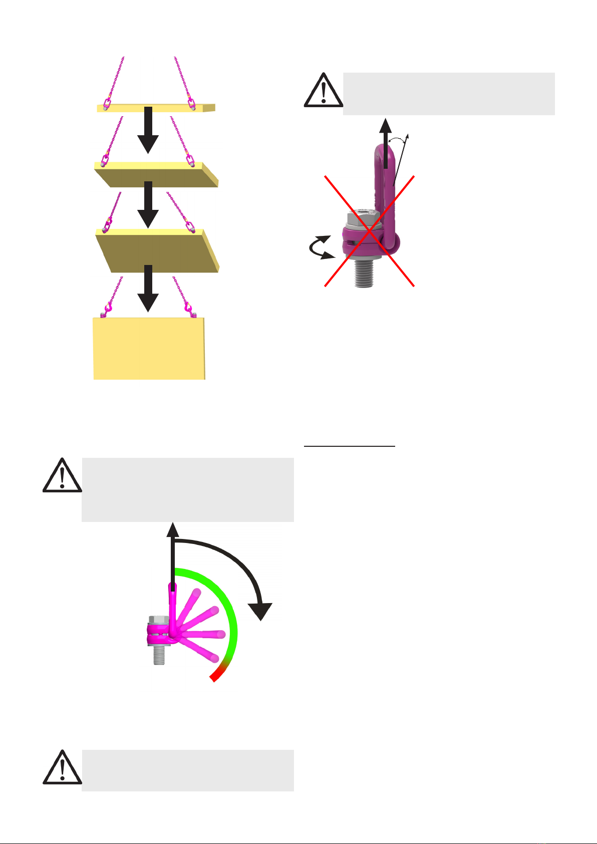
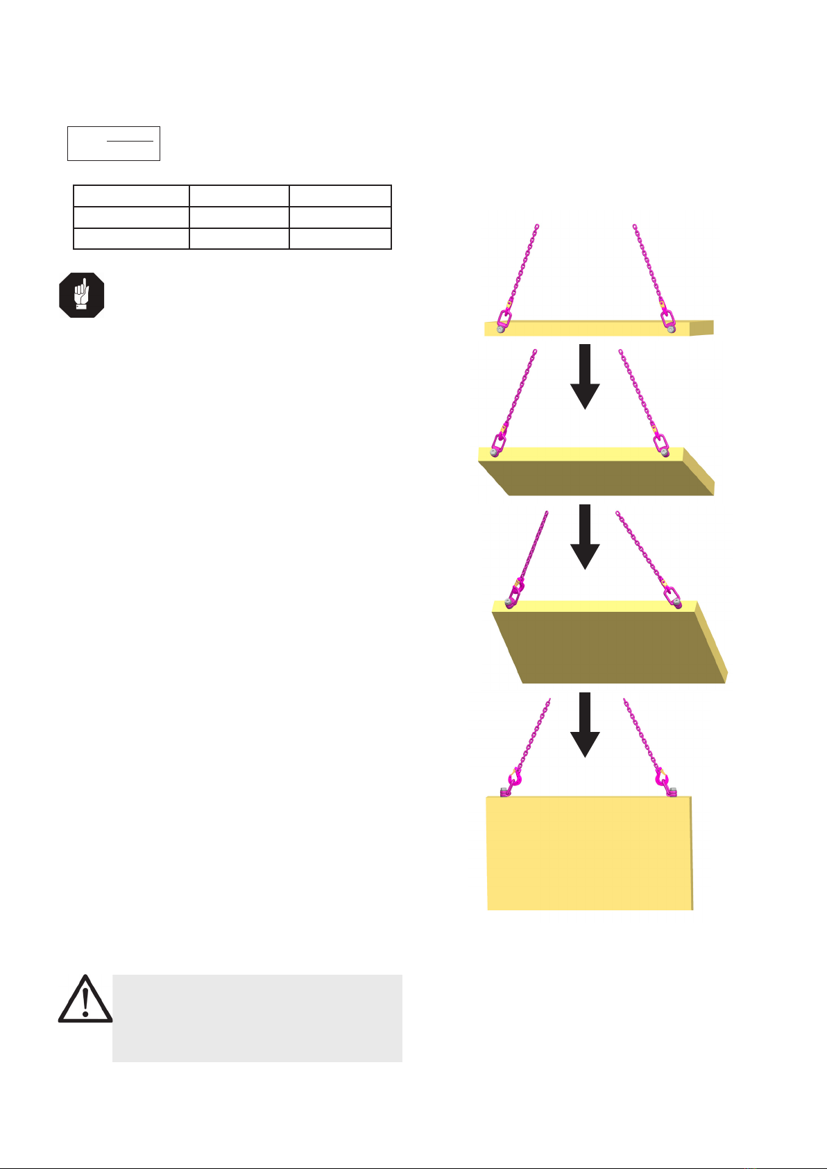
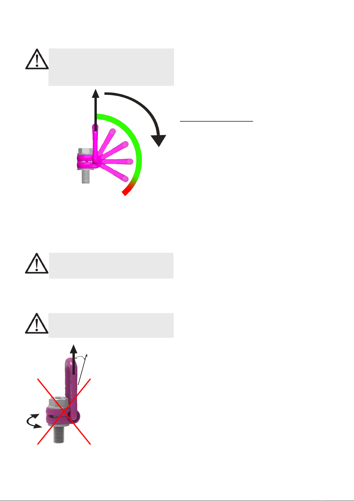
• Führen Sie die Lage der VLBG-PLUS so aus, dass
unzulässige Beanspruchungen wie Verdrehen oder
Umschlagen der Last vermieden werden.
• Einsträngiger Anschlag: Bügel senkrecht über
dem Lastschwerpunkt anordnen
• Zweisträngiger Anschlag: Anordnung beiderseits
und oberhalb des Lastschwerpunktes
• Drei- und viersträngiger Anschlag: Anordnung
gleichmäßig in einer Ebene um den Lastschwer-
punkt.
• Symmetrie der Belastung:
Ermitteln Sie die erforderliche Tragfähigkeit des
einzelnen Anschlagpunktes für symmetrische bzw.
unsymmetrische Belastung entsprechend folgendem
physikalischen formelmäßigen Zusammenhang:
Anzahl der tragenden Stränge ist:
Tabelle 1: Tragende Stränge (vgl. auch Tabelle 2)
HINWEIS
Bei unsymmetrischer Belastung muss die Tragfä-
higkeit eines Anschlagpunktes mindestens dem
Lastgewicht entsprechen.
• Eine plane Anschraubäche (ØD, Tab. 3) mit recht-
winklig dazu eingebrachter Gewindebohrung muss
gewährleistet sein.
WLL = erf. Tragfähigkeit des
Anschlagpunktes/Einzelstrang (kg)
G = Lastgewicht (kg)
n = Anzahl der tragenden Stränge
ß = Neigungswinkel des Einzelstranges
WLL=G
n x cos ß
Die Ausführung des Gewindes muss nach DIN 76
gestaltet sein (Ansenkung max. 1,05xd). Gewindeboh-
rungen müssen so tief eingebracht werden, dass die
Auageäche des Anschlagpunktes anliegen kann.
• Der VLBG-PLUS muss im festgeschraubten Zustand
um 360° drehbar sein. Beachten Sie dazu Folgendes:
• Für einen einmaligen Transportvorgang ist ein
handfestes Anziehen bis zur Anlage der VLBG-
PLUS-Anlageäche auf der Anschraubäche mit
einem Gabelschlüssel ausreichend.
• Soll der VLBG-PLUS dauerhaft an der Last ver-
bleiben, ist ein Anziehen mit dem Anzugsmoment
(+/- 10 %) entspr. Tabelle 3 durchzuführen.
• Bei Wendevorgängen mit dem VLBG-PLUS (siehe
Abschnitt 3.3.2 Zulässige Hebe- und Wendevor-
gänge) ist ein Anziehen mit dem Anzugsmoment
(+/- 10 %) entspr. Tabelle 3 notwendig.
• Bei stoßartiger Belastung oder Vibration, insbeson-
dere bei Durchgangsverschraubungen mit Mutter,
kann es zu unbeabsichtigtem Lösen kommen.
Sicherungsmöglichkeiten: Einhalten des Anzugsmo-
mentes, üssiges Gewindesicherungsmittel wie z.B.
Loctite (an Einsatzfall angepasst, Herstellerangaben
beachten) oder eine formschlüssige Schraubensiche-
rung wie z.B. Kronenmutter mit Splint, Kontermutter
u.s.w.
• Überprüfen Sie abschließend die ordnungsgemäße
Montage (siehe Abschnitt 4 Prüfkriterien).
3.3 Hinweise zum Gebrauch
3.3.1 Allgemeines zum Gebrauch
• Kontrollieren Sie regelmäßig und vor jeder Inbetrieb-
nahme den gesamten Anschlagpunkt auf die fort-
bestehende Eignung als Anschlagmittel, auf festen
Schraubensitz (Anzugsmoment), starke Korrosion,
Verschleiß, Verformungen etc. (siehe Abschnitt 4
Prüfkriterien).
WARNUNG
Falsch montierte oder beschädigte VLBG-PLUS
sowie unsachgemäßer Gebrauch können zu
Verletzungen von Personen und Schäden an
Gegenständen beim Absturz führen.
Kontrollieren Sie alle VLBG-PLUS sorgfältig vor
jedem Gebrauch.
• Stellen Sie vor dem Einhängen des Anschlagmittels
den Anschlagpunkt VLBG-PLUS in Kraftrichtung ein.
Der Lastbügel muss frei beweglich sein und darf sich
nicht an Kanten abstützen.
• Beachten Sie, dass das Anschlagmittel im An-
schlagpunkt VLBG-PLUS frei beweglich sein muss.
Beim An- und Aushängen der Anschlagmittel (An-
schlagkette) dürfen für die Handhabung keine
Quetsch-, Fang-, Scher- und Stoßstellen entstehen.
• Schließen Sie Beschädigungen der Anschlagmittel
durch scharfkantige Belastung aus.
Symmetrie Unsymmetrie
Zweistrang 2 1
Drei-/ Vierstrang 3 1

VLBG-PLUS4
F
3.3.2 Zulässige Hebe- und Wendevorgänge
Bild 1: Möglicher Wendevorgang mit dem VLBG-PLUS
Folgende Vorgänge sind zulässig:
• Wendevorgänge, bei denen der Bügel in Klapprichtung
geschwenkt wird.
WARNUNG
Der Bügel darf sich nicht an Kanten oder anderen
Anbauteilen abstützen bzw. dort anliegen.
Ebenfalls darf das eingehängte Anschlagmittel
den Schraubenkopf nicht berühren.
Bild 2: Schwenken in Klapprichtung
• Wendevorgänge, bei denen der VLBG-PLUS um die
Schraubenachse gedreht wird (Ausnahme: siehe Ab-
schnitt 3.3.3 Verbotene Hebe- und Wendevorgänge).
Nach einer maximalen Drehung um 180° muss das
Anzugsmoment der Schraube überprüft werden.
WARNUNG
Überprüfen Sie die vorgeschriebenen Anzugs-
momente vor jedem Hebe- bzw. Wendevorgang.
Bild 3: Verbotene
Drehbewegung bei
Belastung in Achsrichtung
F
15°
3.3.3 Verbotene Hebe- und Wendevorgänge
Folgende Vorgänge sind verboten:
WARNUNG
Das Drehen des VLBG-PLUS bei Belastung in
Achsrichtung der Schraube (+15°) ist verboten.
3.4 Hinweise zur regelmäßigen Überprüfung
Prüfen Sie durch einen Sachkundigen in Zeitabständen,
die sich nach ihrer Beanspruchung richten, mindestens
jedoch 1x jährlich, die fortbestehende Eignung des
Anschlagpunktes (siehe Abschnitt 4 Prüfkriterien).
Je nach Einsatzbedingungen, z.B. bei häugem Einsatz,
erhöhtem Verschleiß oder Korrosion, können Prüfungen
in kürzeren Abständen als einem Jahr erforderlich sein.
Die Überprüfung ist auch nach Schadensfällen und be-
sonderen Vorkommnissen notwendig.
4 Prüfkriterien
Beachten und kontrollieren Sie folgende Punkte vor jeder
Inbetriebnahme, in regelmäßigen Abständen, nach der
Montage und nach besonderen Vorkommnissen:
• Richtige Schrauben- und Mutterngröße, Schrau-
bengüte und Einschraublänge
• auf festen Schraubensitz achten --> Überprüfung des
Anzugsmomentes
• Vollständigkeit des Anschlagpunktes
• Vollständige, lesbare Tragfähigkeitsangabe sowie
Herstellerzeichen
• Verformungen an tragenden Teilen wie Grundkörper,
Einhängebügel und Schraube
• mechanische Beschädigungen wie starke Kerben,
insbesondere in auf Zugspannung belasteten Berei-
chen
• Querschnittsveränderungen durch Verschleiß > 10 %
• starke Korrosion
• Anrisse an tragenden Teilen
• Funktion und Beschädigung der Schrauben, Muttern
sowie Schraubengewinde
• leichtes Drehen des VLBG-PLUS muss gewährleistet
sein
RUD-Komponenten sind entsprechend DIN EN 818 und
1677 für eine dynamische Belastung von 20.000 Last-
wechseln ausgelegt.
Die BG/DGUV empehlt: Bei hoher dynamischer Bela-
stung mit hohen Lastspielzahlen (Dauerbetrieb) muss die
Tragspannung entsprechend Triebwerksgruppe 1Bm(M3
nach DIN EN 818-7) reduziert werden.

5VLBG-PLUS
Please read user instruction before
initial operation of the bolt-on lifting
point VLBG-PLUS.Makesurethatyouhave
comprehend all subjected matters.
Non observance can lead to serious
personal injuries and material damage
and eliminates warranty.
1 Safety instructions
ATTENTION
Wrong assembled or damaged VLBG-PLUS as
well as improper use can lead to injuries of per-
sons and damage of objects when load drops.
Please inspect all VLBG-PLUS before each use.
• Reference should be made to German Standards ac-
cord. BGR 500 (DGUV rules 100-500) or other country
specic statutory regulations and inspections are to be
carried out by competent persons only.
• The VLBG-PLUS must be rotatable 360° when in-
stalled.
2 Intended use
VLBG-PLUS must only be used for the assembly of the
load or at load accepting means
Their usage is intended to be used as lifting means.
The VLBG-PLUS can also be used as lashing points for
the xture of lashing means.
The VLBG-PLUS must only be used in the here described
usage purpose.
3 Assembly- and instruction manual
3.1 General information
• Effects of temperature:
Due to the DIN/EN bolts that are used in the VLBG-PLUS,
the working load limit must be reduced accordingly:
-40°C to 100°C --> no reduction (-40°F to 212°F)
100°C to 200°C minus 15 % (212°F to 392°F)
200°C to 250°C minus 20 % (392°F to 482°F)
250°C to 350°C minus 25 % (482°F to 662°F)
Temperatures above 350°C (662°F) are not
permitted.
Please observe the maximum usage temperature of
the supplied nuts (optionally):
• Clamping nuts according to DIN EN ISO 7042
(DIN 980) must only be used up to +150°C at the
max (302°F).
• Collar nuts according to DIN 6331 can be used
up to +300°C. Please note also the reduction
factors (572°F).
• RUD-Lifting points must not be used under chemical in-
uences such as acids, alkaline solutions and vapours
e.g. in pickling baths or hot dip galvanising plants. If
this cannot avoided, please contact the manufacturer
indicating the concentration, period of penetration and
temperature of use.
• The places where the lifting points are xed should be
marked with colour.
• VLBG-PLUS lifting points from RUD are supplied with a
crack test inspected hexagon bolt (length up to Lmax,
see chart 3).
M8-M24: ICE-Bolt
M27-M48: 10.9 bolt
Only the corresponding strength class must be
used for the choosen size!
• If self provided 10.9 bolts are used for the sizes M27-
M48, these parts must be 100 % free of cracks.
Original ICE-Bolts of the sizes M8-M24 can be ordered
from RUD. The minimum notch bar impact test value
at the lowest possible temperature must be at least 36
Joule. This is a requirement of the testing principles for
lifting points according to GS MO 15-04 (Point 6.4.1).
HINT
To remove bolt from the body, use a ham-
mer and knock front end of the bolt.
Disassambly and exchange of bolt must only be
carried out by a competent person.
Versions
• The type VLBG-PLUS 7 t M36 is only delivered with
a special bolt, therefore it is not possible to use
a DIN/EN-bolt.
• RUD supplies the Vario length complete with a
washer and crack-detected nut corresponding to
DIN EN ISO 7042 (DIN 980) or will be supplied with
a crack inspected collar nut acc. to DIN 6331.
• If the VLBG-PLUS is used exclusively for lashing, the
value of the working load limit can be doubled.
LC = permissible lashing capacity = 2 x WLL
3.2 Hints for the assembly
Basically essential:
• The material construction to which the lifting point
will be attached should be of adequate strength
to withstand forces during lifting without deforma-
tion. The German testing authority BG, recom-
mends the following minimum for bolt lengths:
1 x M in steel (minimum quality S235JR [1.0037])
1,25 x M in cast iron (for example GG 25)
2 x M in aluminium alloys
2,5 x M in aluminium-magnesium alloys
(M = diameter of RUD lifting point bolt, for ex. M 20)
• When lifting light metals, nonferrous heavy metals and
gray cast iron the thread has to be chosen in such a
way that the working load limit of the thread corre-
sponds to the requirements of the respective base
material.
• The lifting points must be positioned on the load in
such a way that movement is avoided during lifting:
• For single leg lifts, the load ring should be
positioned vertically above the centre of
gravity of the load.
• For two leg lifts, the lifting points must be
equidistant to/or above the centre of gravity
of the load.
• For three and four leg lifts, the lifting points
should be arranged symmetrically around the
centre of gravity in the same plane, if possible.
ENGLISH

VLBG-PLUS6
WLL = working load limit
G = load weight (kg)
n = number of load bearing legs
ß = angle of inclination of the chain to the vertical
WLL=G
n x cos ß
• All ttings connected to the VLBG-PLUS should be
free moving. When connecting and disconnecting the
lifting means (sling chain) pinches and impacts should
be avoided.
• Damage of the lifting means caused by sharp edges
should be avoided as well.
3.3.2 Allowed lifting and turning operations
Pic. 1: Possible turning operation with the VLBG-PLUS
WLL=G
n x cos ß
• Load symmetry:
The working load limit of individual RUD lifting points
are calculated using the following formula and are
based on symmetrical loading:
The calculation of load bearing legs is as follows:
l
table 1: Load bearing strands (see table 2)
HINT
With unsymmetrical loads, the WLL of each Lif-
ting Point must be at least as high as the weight
of the load.
• A plane bolt-on surface (ØD) with a perpendicular
thread hole must be guaranteed. The thread must be
carried out acc. to DIN 76 (countersink max. 1.05xd).
Tapped holes must be machined deep enough so that
the bearing surface of the lifting point will be supported.
• The VLBG-PLUS must be rotatable 360° when in-
stalled. Please observe the following:
• For a single use hand tightening with a spanner
is sufciant. Bolt supporting area must sit proper
on bolt-on surface.
• For long term application the VLBG-PLUS must
be tightened with torque according to table 3
(+/- 10 %).
• When turning loads using the VLBG-PLUS (see
chapter 3.3.2 permissible lifting- and turning pro-
cess) it is necessary to tighten the bolt with a torque
(+/- 10 %) acc. to chart 3.
• With shock loading or vibrations, especially at
through hole fixtures with a nut at the end of
the bolt, accidential release can occure.
Securing possibilities: Observe torque moment, use
liquid securing glue f.e. Loctite (can be adapted to the
usage, observe manufacturer hints) or assemble a
form closure bolt locking device f.e. a castle nut with
cotter pin, locknut etc.
• Finally check the proper assembly (see chapter 4
Inspection criteria).
3.3 User instructions
3.3.1 General information for the usage
• Before every usage, control in regularly periods the
whole lifting point in regard of the continuous aptitude
as a lifting mean, whether it is tightened (torqued), or
has strong corrosion, wear, deformations etc. (see
chapter 4 Inspection criteria).
ATTENTION
Wrong assembled or damaged VLBG-PLUS as
well as improper use can lead to injuries of per-
sons and damage of objects when load drops.
Please inspect all VLBG-PLUS before each use.
• Adjust to the direction of pull, before attaching to the
lifting means. The load ring should be free movable
and must not touch edges.
symmetrical asymmetrical
two leg 2 1
three / four leg 3 1

7VLBG-PLUS
F
The following turning operations are allowed
• Turning operations where the load ring will be turned
into the load direction
WARNING
The load ring must not support itself at edges or
other attachments.
Also the attached lifting mean must not touch the
head oft he bolt.
Pic. 2: Pivoting in load direction
• Turning operations where the VLBG-PLUS will be
turned around the bolt axle (exception: see chapter
3.3.3 Forbidden lifting and turning operations).
After a full turn by 180° the torque of the bolt must be
checked.
WARNING
Observe the requested torque value before each
lifting or turning operation.
3.3.3 Forbidden lifting and turning operations
The following operations are forbidden:
WARNING
The turning of the VLBG-PLUS under load in
the direction of the bolt axle (+15°) is forbidden.
3.4 Hints for periodical inspections
Have VLBG-PLUS checked by a competent person in
periods which are determined by the usage, but at least
1x per year, in regard of the ongoing appropriateness of
the lifting point (see chapter 4 Inspection criteria).
Depending on the usage conditions, f.e. frequent usage,
increased wear or corrosion, it might be necessary to check
in shorter periods than one year. The inspection has also
to be carried out after accidents and special incidents.
4 Inspection criteria
Observe and control the following points before each
operation, in regularly periods, after the assembly and
special incidents.
• Ensure correct bolt and nut size, quality and length.
• Ensure compatibility of bolt thread and tapped hole
- control of the torque
• The lifting point should be complete.
• The working load limit and manufacturers stamp should
be clearly visible.
• Deformation of the component parts such as body, load
ring and bolt.
• Mechanical damage, such as notches, particularly in
high stress areas.
• Wear should be not more than 10 % of cross sectional
diameter.
• Evidence of corrosion.
• Evidence of cracks.
• Damage at the bolt, nut and/or thread.
• The body of the VLBG-PLUS must be free to rotate.
RUD components are designed for a dynamical loading
of 20 000 load cycles at nominal working load.
The BG/DGUV recommends: At a high dynamic loading
with high numbers of load cycles (continious work) the
bearing stress acc. to FEM group 1Bm(M3 acc. to DIN
818-7) must be reduced.
Pic. 3: Forbidden turning
direction at loading in the
direction of the axle.
F
15°

VLBG-PLUS8
Lisez attentivement le manuel
d‘utilisation avant d‘utiliser l’anneau de
levage décentré à grande ouverture
(appeléVLBG-PLUSparla suite).Assurez-
vous que vous avez bien compris le
contenu.
Le non-respect des instructions peut
entraîner des dommages corporels et
matériels, et annuler la garantie.
1 Consignes de sécurité
AVERTISSEMENT
Un VLBG-PLUS mal monté ou endommagé de
même qu‘une utilisation non conforme peuvent
entraîner des blessures de personnes ou dégâts
matériels en cas de chute.
Contrôlez soigneusement les VLBG-PLUS avant
chaque utilisation.
• Utilisation seulement par des personnes compétentes
en la matière, en observant l´article R233-11 du code
du travail, et les instructions propres au pays corre-
spondants.
• L’anneau VLBG-PLUS doit pouvoir tourner sur 360°
en position vissée à fond.
2 Utilisation conforme
Les VLBG-PLUS peuvent être utilisés uniquement xés
sur une charge ou un accessoire de préhension.
Ils sont conçus pour être connectés aux élingues.
Les VLBG-PLUS peuvent aussi être utilisés comme an-
neaux d’arrimage pour systèmes d’arrimage.
Les VLBG-PLUS peuvent être uniquement utilisés dans
les cas précédemment décrits.
3 Instructions d’assemblage/mode d´emploi
3.1 Informations générales
• Effets de la température sur la CMU :
A cause des vis DIN/EN qu’on utilise pour l’anneau
VLBG-PLUS, il faut réduire la charge maximale
d’utilisation comme suit :
-40° à 100°C sans reduction (-40°F à 212°F)
100° à 200°C moins 15 % (212°F à 392°F)
200° à 250°C moins 20 % (392°F à 482°F)
250° à 350°C moins 25 % (482°F à 662°F)
Des expositions à températures supérieures à
350°C (662°F) ne sont pas permises.
Faites attention à la température d‘utilisation maxi-
male des écrous livrés (optionnel).
• Les écrous de serrage conformes à la DIN EN
ISO 7042 (DIN 980) peuvent être employés
jusqu‘à maximum +150°C
• Les écrous à collet conformes à la DIN 6331
peuvent être employés jusqu‘à +300°C. Faites
également attention aux facteurs de réduction.
• Les anneaux de levage RUD ne doivent pas être
exposés aux produits chimiques agressifs, les acides
ou leurs vapeurs.
• Les points où on xe les anneaux de levage doivent
être marqués avec une couleur contrastée facilement
remarquable.
• Les VLBG-PLUS sont fournis par RUD avec une vis à
tête hexagonale testée anti-ssures (longueur Lmax,
voir le tableau 3).
M8 - M24: vis ICE
M27- M48: 10.9
Seules les classes de résistance correspondantes
peuvent être utilisées !
• Lorsque vous utilisez vos propres vis 10.9 pour
les dimensions M27 à M48 vériez qu’elles soient
100 % sans ssures. Les vis ICE d’origine en M8 à
M24 sont livrables en pièces détachées chez RUD.
La résilience moyenne à la température minima-
le d‘utilisation admissible doit être d‘au minimum
36 J.Ceci est imposé dans les normes de contrôle des
anneaux de levage GS MO 15-04 (section 6.4.1).
INDICATION
Pour le remplacement de la vis montée, vous
pouvez utiliser un marteau pour l’extraire du
corps de l’anneau.
Le démontage et l‘échange doivent être réalisés
uniquement par un expert !
Versions
• Le type VLBG-PLUS 7 t M36 est livré uniquement
avec une vis spéciale, il n’est donc pas possible
d’utiliser une vis ou tige letée EN/DIN. Néan-
moins, pour une grande quantité, nous pouvons
vous livrer des vis en grande longueur.
• RUD livre les longueurs spéciales (Vario) avec une
rondelle et un écrou 100 % testé anti-ssures selon
DIN EN ISO 7042 (DIN 980) ou avec un écrou à
collet testé anti-ssures selon DIN 6331.
• En cas d’utilisation des anneau de levage uniquement
pour l’arrimage, on peut doubler la valeur de la charge
d’utilisation :
LC (Lashing capacity) = 2 x charge d’utilisation (CMU)
3.2 Notes pour l‘installation
Fondamentalement il faut que :
• Le système auquel les anneaux de levage seront atta-
chés doit avoir une stabilité sufsante pour résister sans
se déformer, aux forces appliqués pendant l´utilisation.
Ils est recommandé par les syndicats professionnels
pertinents d´utiliser comme longueur minimum de
serrage les coefcients multiplicateur suivants :
1 x pour l´acier (qualité minimum S235JR
[1.0037])
1,25 x pour la fonte (par exemple GG 25)
2 x pour l´aluminium
2,5 x pour les métaux légers à faible résistance
(M = diamètre du boulon, par exemple M20)
• Pour les utilisations avec des métaux légers, métaux
lourds non-ferreux et fontes grises il faut choisir le -
letage de telle manière à ce que la charge d’utilisation
du letage corresponde bien aux exigences du matériel
de base respectif.
• Les anneaux de levage doivent être positionnés sur
la charge de telle manière à éviter tout mouvement
défavorable pendant le levage (tel que renversement,
retournement, etc.).
• Pour le levage à brin unique, l’étrier disposé doit
être verticalement au-dessus du centre de gravité.
FRANCAIS

9VLBG-PLUS
• Pour le levage à deux brins, les anneaux
de levage doivent être au-dessus ou sur les
cotés du centre de gravité de la charge, à
égale distance.
• Pour le levage à trois et à quatre brins, les
anneaux de levage doivent être placés de
façon symétrique autour du centre de gravité
de la charge, tous au même niveau.
• Symétrie de la charge :
Les charges maximales d’utilisation de l’anneau esca-
motable pour charges symétriques et asymétriques
sont calculées selon la formule suivante :
Les brins portants sont calculés comme suit :
Tableau 1 : brins portants (c.f. aussi tableau 2)
IMPORTANT
En chargement asymétrique, la CMU de l’anneau
de levage doit être au moins égale au poids de
la charge.
• La surface de vissage plane (diamètre ØD, voir tableau
3) avec son letage foré perpendiculairement doit être
garantie.
• Les trous borgnes doivent être percés avec une
profondeur sufsante pour que l’ embase (la surface
d’appui) puisse épouser la surface de xation de la
pièce à lever.
• L’anneau VLBG-PLUS doit pouvoir tourner sur 360°
en position vissée à fond. Faites attention également
aux points suivant :
• Pour une manutention unique un serrage à la
main jusqu´au contact de l´embase du VLBG-PLUS
à la surface de la charge, avec clé plate sans ac-
cessoires de prolongation (tel que tube ou ....) de
l´outil de serrage suft.
• Pour une application à longue durée il faut serrer
avec le couple de serrage (+/- 10 %) indiqué dans
le tableau 3.
• En cas de retournement avec le VLBG-PLUS (cf.
chapitre 3.3.2 opérations de levage et retournement
admissibles), il est nécessaire de visser avec le
couple de serrage (+/-10 %) comme indiqué dans
le Tableau 3.
• En cas de secousses par à coups ou vibrations, en
particulier lorsque la charge est xée par une vis écrou
débouchantes, des risques de dévissage peuvent
survenir de manière inopinée, pouvant entraîner des
décrochages.
Possibilités de sécurité : enduire le letage avec
un produit xant par exemple du Loctite (type adapté
à l´utilisation désirée, suivre les instructions du fabri-
cant), l’utilisation d’un écrou à freins avec goupille de
sécurité, l’utilisation d’un contre-écrou.
• Pour nir, contrôlez le montage réglementaire (cf.
chapitre 4 sur les critères de contrôles).
3.3 Instructions concernant l‘utilisation
3.3.1 Infos générales concernant l‘utilisation
• Inspectez régulièrement et avant chaque utilisation
l’anneau de levage dans sa globalité quant au maintien
de son aptitude comme accessoire de levage, l’assise
de l´embase sur la surface de la charge (couple de
serrage), fortes corrosions, usures, déformations, etc
(cf. chapitre 4 des critères de contrôles).
ATTENTION
Un VLBG-PLUS mal monté ou endommagé de
même qu‘une utilisation non conforme peuvent
entraîner des blessures de personnes ou dégâts
matériels en cas de chute.
Contrôlez soigneusement les VLBG-PLUS avant
chaque utilisation.
• Avant d’accrocher l’anneau, veuillez l’ajuster en direc-
tion de la traction. L’anneau doit pouvoir se mouvoir
librement et ne doit pas pouvoir toucher une (des)
arête(s).
• Toutes les pièces connectées à l’anneau VLBG-
PLUS doivent pouvoir se mouvoir librement. Lors de
l’accrochage et du décrochage de l´élingue (ex : élingue
en chaîne) éviter touts écrasements et/ou impacts.
• Il faut aussi éviter des détériorations causées par des
angles vifs.
3.3.2 Opérations de levage et retournement
admissibles
Illustration 1 : Retournement possible avec le VLBG-PLUS
WLL = CMU = Charge Maximale d´ Utilisation (kg)
G= poids de la charge (kg)
n = nombre de brins portants
ß= angle d’inclinaison du brin unique
WLL=G
n x cos ß
symétrique asymétrique
deux brins 2 1
trois / quatre brins 3 1

VLBG-PLUS10
F
Les opératons suivantes sont admissibles :
• Opérations de retournement avec l’étrier déplié hors
de l’anneau
ATTENTION
L’étrier ne peut pas s‘appuyer ni reposer sur une
arête ou autre élément annexe.
Egalement l’élingage accroché ne doit pas tou-
cher la tête de vis.
Image 2 : étrier déplié hors de l’anneau
• Opération de retournement auquel le VLBG-PLUS a
tourné autour de l‘axe de sa vis. Après une rotation
maximale de 180°, le couple de serrage de la vis doit
être contrôlé.
ATTENTION
Contrôlez les couples de serrage prescrits avant
chaque levage ou opération de retournement.
3.3.3 Opérations de levage et retournement
Les opérations suivantes sont interdites :
ATTENTION
La rotation du VLBG-PLUS par chargement dans
la direction de l’axe de la vis (15 °) est interdit.
3.4 Remarques relatives au contrôles réguliers
Un technicien compétent ou une personne qualifiée
doit examiner à intervalles réguliers, variables se-
lon les besoins et l‘utilisation (au minimum une fois
par an) le maintien de l’aptitude de l’anneau de le-
vage (cf. chapitre 4 sur les critères de contrôles).
Selon les conditions d’utilisation, par exemple en utilisati-
on fréquente, avec usure ou corrosion augmentées, des
examens peuvent être nécessaires dans de plus courts
délais qu‘une année. Le contrôle est aussi nécessaire
après des cas de dommage ou cas particuliers.
4 Critères de contrôles
Faites attention et contrôlez les points suivants avant
chaque mise en service et à intervalles réguliers, après
le montage et après les cas particuliers :
• bonne taille de la vis et du boulon, bonne longueur de
vissage et surtout bonne qualité/classe.
• vérier la bonne assise de toute l´embase de l´anneau
sur la surface de la charge
• vérication du couple de serrage
• vérier la compatibilité du letage de la vis et du trou
leté
• vérier l’intégrité de l´anneau escamotable
• l’indication de la charge maximale d’utilisation et la
marque du fabricant doivent être complètes et lisibles.
• vérier les déformations de pièces portantes comme
pièce de base, anneau et vis.
• vérier des détériorations mécaniques comme des
fortes rainures en particulier sur les parties portantes.
• vérier les éventuelles modications du diamètre cau-
sées par usure > 10 %.
• vérier la forte corrosion.
• vérier les ssures sur les parties portantes.
• vérier le bon fonctionnement et l´état des boulons,
vis, écrous ainsi que de leurs letages.
• la rotation libre et facile de l’anneau VLBG-PLUS doit
être garantie.
Les chaînes et accessoires VIP et Grade 80 de RUD sont
réalisés, conformément à DIN EN 818 et 1677, pour une
charge dynamique de 20.000 cycles de chargements de
charge.
Le BG/DGUV recommande : lors d’une plus forte sollicita-
tion avec un nombre de cycle supérieur (utilisation conti-
nue), la tension de portée doit être réduite conformément
à la classication 1Bm(M3 selon DIN EN 818-7)
Image 3 : mouvement de
rotation interdit en charge-
ment dans la direction de
l’axe de la vis
F
15°

11VLBG-PLUS
Anschlagart
Method of lift
Type d‘ élingage
Anzahl der Stränge
Number of legs 1 1 2 2 2 2 2 3 & 4 3 & 4 3 & 4
Nombre de brins
Neigungswinkel <ß
Angle of inclination <ß 0° 90° 0° 90° 0-45° 45-60° unsymm. 0-45° 45-60° unsymm.
Angle d‘ inclinaison <ß
Faktor/factor/Facteur 1 1 2 2 1,4 1 1 2,1 1,5 1
Type Gewinde für max. Gesamt-Lastgewicht in Tonnen, festgeschraubt und in Zugrichtung eingestellt
Thread WLL in tonnes, bolted and adjusted to the direction of pull
Filetage charge d’utilisation en tonnes, vissé à fond et ajusté en direction de traction
VLBG-PLUS 0,63t M 8 0,63 0,63 1,26 1,26 0,88 0,63 0,63 1,26 0,94 0,63
VLBG-PLUS 0,9t M 10 0,9 0,9 1,8 1,8 1,26 0,9 0,9 1,9 1,35 0,9
VLBG-PLUS 1,35t M 12 1,35 1,35 2,7 2,7 1,9 1,35 1,35 2,8 2 1,35
VLBG-PLUS 1,2t M 14 1,2 1,2 2,4 2,4 1,7 1,2 1,2 2,5 1,8 1,2
VLBG-PLUS 2t M 16 2 2 4 4 2,8 2 2 4,2 3 2
VLBG-PLUS 2t M 18 2 2 4 4 2,8 2 2 4,2 3 2
VLBG-PLUS 3,5t M 20 3,5 3,5 7 7 4,9 3,5 3,5 7,35 5,25 3,5
VLBG-PLUS 4,5t M 24 4,5 4,5 9 9 6,3 4,5 4,5 9,5 6,75 4,5
VLBG-PLUS 6,7t M 30 6,7 6,7 13,4 13,4 9,4 6,7 6,7 14 10 6,7
VLBG-PLUS 8t M 36 8 8 16 16 11,2 8 8 16,8 12 8
VLBG-PLUS 10t M 42 10 10 20 20 14 10 10 21 15 10
VLBG-PLUS 15t M 42 15 15 30 30 21 15 15 31,5 22,5 15
VLBG-PLUS 20t M 48 20 20 40 40 28 20 20 42 30 20
Type Gewinde für max. Gesamt-Lastgewicht in lbs, festgeschraubt und in Zugrichtung eingestellt
Thread WLL in lbs, bolted and adjusted to the direction of pull
Filetage charge d’utilisation en lbs, vissé à fond et ajusté en direction de traction
VLBG-PLUS 0,63t M 8 1388 1388 2776 2776 1943 1388 1388 2914 2082 1388
VLBG-PLUS 0,9t M 10 1983 1983 3966 3966 2776 1983 1983 4161 2974 1983
VLBG-PLUS 1,35t M 12 2975 2975 5950 5950 4165 2975 2975 6247 4462 2975
VLBG-PLUS 1,2t M 14 2644 2644 5288 5288 3701 2644 2644 5552 5552 2644
VLBG-PLUS 2t M 16 4408 4408 8816 8816 6171 4408 4408 9256 9256 4408
VLBG-PLUS 2t M 18 4408 4408 8816 8816 6171 4408 4408 9256 6612 4408
VLBG-PLUS 3,5t M 20 7714 7714 15428 15428 10799 7714 7714 16199 11571 7714
VLBG-PLUS 4,5t M 24 9918 9918 19836 19836 13885 9918 9918 20827 14877 9918
VLBG-PLUS 6,7t M 30 14766 14766 29532 29532 20672 14766 14766 31008 22149 14766
VLBG-PLUS 8t M 36 17632 17632 35264 35264 24684 17632 17632 37027 26448 17632
VLBG-PLUS 10t M 42 22040 22040 44080 44080 30856 22040 22040 46284 33060 22040
VLBG-PLUS 15t M 42 33060 33060 66120 66120 46284 33060 33060 69426 49590 33060
VLBG-PLUS 20t M 48 44080 44080 88160 88160 61712 44080 44080 92568 66120 44080
Tabelle 2: Tragfähigkeiten in Tonnen (oben) und in lbs (unten)
Table 2: WLL in tons (above / top) and in lbs (below / bottom)
Tableau 2 : CMU en tonnes (en haut) et en lbs (en bas)
Abb./Pic./Image 4: Belastung über Kopf /
Overhead loading / Chargement au-dessus de la tête
VERBOTEN!
(Belastung über Kopf)
Forbidden!
(Overhead loading)
INTERDIT!!
(Chargement au-dessus de la tête)
F

VLBG-PLUS12
Typ Tragf. Gewicht A B C D E F G H H J K L L M N SW ISK T Anzugs- Artikel-Nr.
Type WLL weight Stand.max. Stand. max. moment reference/réf.
Désignation CMU Poids couple Standard Vario
[t] [kg] Torque
VLBG-PLUS 0,63t M8 0,63 0,3 30 54 34 24 40 12 29 11 76 75 45 40 105 8 32 13 5 75 30 Nm 8504651 8600470
VLBG-PLUS 0,9t M10 0,9 0,32 30 54 34 24 39 12 29 15 96 75 45 44 125 10 32 17 6 75 60 Nm 8504652 8600471
VLBG-PLUS 1,35t M12 1,35 0,33 32 54 34 26 38 12 29 18 116 75 45 47 145 12 32 19 8 75 150 Nm 8504653 8600472
VLBG-PLUS 1,2t M14 1,2 0,52 33 56 36 30 39 13,5 36 24 34 86 47 60 70 14 38 24 10 85 150 Nm 8504654 8600473
VLBG-PLUS 2t M16 2 1,3 33 56 36 30 39 13,5 36 22 149 86 47 58 185 16 38 24 10 85 150 Nm 8504655 8600474
VLBG-PLUS 2t M18 2 1,3 50 82 54 45 50 16,5 43 37 222 130 78 80 90 18 48 30 12 110 200 Nm 8504656 8600475
VLBG-PLUS 3,5t M20 3,5 1,3 50 82 54 45 55 16,5 43 32 187 113 64 75 230 20 48 30 12 110 400 Nm 8504657 8600476
VLBG-PLUS 4,5t M24 4,5 1,5 50 82 54 45 67 18 43 37 222 130 78 80 265 24 48 36 14 125 760 Nm 8504659 8600478
VLBG-PLUS 6,7t M30 6,7 3,3 60 103 65 60 67 22,5 61 49 279 151 80 110 340 30 67 46 17 147 1000 Nm 8504661 8600480
VLBG-PLUS 8t M36 8 3,4 77 122 82 70 97 26,5 77 63 223 205 110 140 300 36 87 55 22 197 800 Nm 8504662 8600481
VLBG-PLUS 10t M42 10 6,7 77 122 82 70 94 26,5 77 73 273 205 110 150 350 42 70 65 24 197 1000 Nm 8504663 8600482
VLBG-PLUS 15t M42 15 11,2 95 156 100 85 109 36 87 63 413 230 130 150 500 42 100 65 24* 222 1500 Nm 8504664 8600483
VLBG-PLUS 20t M48 20 11,6 95 156 100 95 105 36 87 73 303 230 130 160 350 48 100 75 27 222 2000 Nm 8504665 8600484
B
C
M
A
D
HG
L
T
E
F
K
J
N
max.
max.
D
G
T
F
E
H
L
Tabelle 3: Maßübersicht Technische Änderungen vorbehalten
Table 3: Dimensioning Subject to technical modications
Tableau 3 : Aperçu des dimensions Sous réserve de modications techniques
SW = Schlüsselweite / wrench size / ouverture de clé
ISK = Innensechskant / internal hexagon / hexagone intérieur
* ab L=351 mm ohne Innensechskant
* from L=351 mm without internal hexagon
* á partier de L=351 mm sans hexagone intérieur
Other manuals for VLBG-PLUS
1
Table of contents
Languages:
Other RUD TV Mount manuals