RUD LPW 300 User manual

1
LPW
RUD Ketten
Rieger & Dietz GmbH u. Co. KG
73428 Aalen/Germany
Tel. +49 7361 504-1370
Fax +49 7361 504-1460
www.rud.com
RUD-Art.-Nr.: 7993141 - EN - V03 / 10.021
LPW
Lashing Point Welding
Safety instructions
This safety instruction/declaration must be kept for the
entire time usage time and forwarded with the product.
TRANSLATION OF THE ORIGINAL INSTRUCTIONS
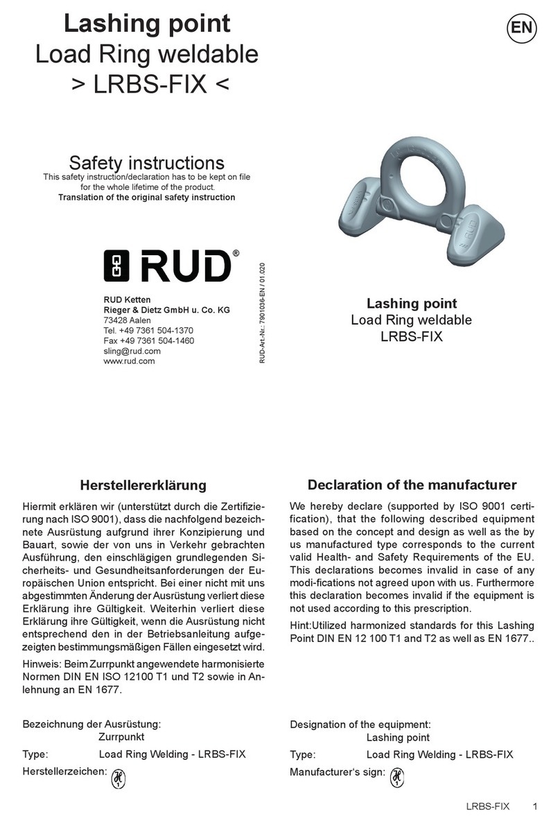
Lashing Point Welding LPW
180°
2:1
Bezeichnung der Ausrüstung:
Zurrpunkt
Type: Lashing Point Welding - LPW
Herstellerzeichen:
Herstellererklärung
Hiermit erklären wir (unterstützt durch die Zertizierung
nach ISO 9001), dass die nachfolgend bezeichnete Aus-
rüstung aufgrund ihrer Konzipierung und Bauart, sowie der
von uns in Verkehr gebrachten Ausführung, den einschlä-
gigen grundlegenden Sicherheits- und Gesundheitsanfor-
derungen der Europäischen Union entspricht. Bei einer
nicht mit uns abgestimmten Änderung der Ausrüstung
verliert diese Erklärung ihre Gültigkeit. Weiterhin verliert
diese Erklärung ihre Gültigkeit, wenn die Ausrüstung nicht
entsprechend den in der Betriebsanleitung aufgezeigten
bestimmungsmäßigen Fällen eingesetzt wird.
Hinweis: Beim Zurrpunkt angewendete harmonisierte
Normen DIN EN ISO 12100 T1 und T2 sowie in Anlehnung
an EN 1677.
Declaration of the manufacturer
We hereby declare (supported by ISO 9001 cer-
tication), that the following described equipment
based on the concept and design as well as the by
us manufactured type corresponds to the current
valid Health- and Safety Requirements of the EU.
This declarations becomes invalid in case of any
modications not agreed upon with us. Furthermore
this declaration becomes invalid if the equipment is
not used according to this prescription.
Hint: Utilized harmonized standards for this Lashing
Point DIN EN 12 100 T1 and T2 as well as EN 1677.
Designation of the equipment:
Lashing point
Type: LPW
Manufacturer‘s sign:
EN

2LPW
Carefully read the operating instructions
before using the RUD lashing point LPW.
Ensure that you have understood all the
contents.
Non-observation of the instructions can
lead to injuries or damage and will invali-
date the guarantee.
1 Safety instructions
WARNING
Wrong assembled or damaged lashing
points as well as impropriate use can lead
to injuries of persons and property damage.
Inspect all lashing points before each use
carefully!
• Keep all body parts (ngers, hands, arms etc.) out
from the danger zone during the lashing process
(risk of squeezing).
• RUD lashing points LPW may only be used by
authorised and instructed persons in compliance
with the DGUV Regulations 109-017 and in com-
pliance with any valid national regulations if used
outside Germany.
• Attention - when suspension ring pivots there is a
risk of pinching.
• Do not exceed the LC (Lashing Capacity) indicated
on the lashing point.
• No technical modications must be made to the
LPW.
• No persons are allowed in the danger zone.
• Damaged or worn LPW must not be used.
2 Intended use
RUD lashing points LPW must only be used to attach
lashing means. The LPW can also be used as lashing
points for the xture of lashing means.
In general, lashing points must not be used for lifting.
A full working load in all directions is allowed.
The LPW must only be used in the here described
usage purpose.
3 Assembly- and instruction
3.1 General information
• Eects of temperature:
RUD lashing points LPW are suitable for the tem-
perature range from -40°C up to 400°C. For the
use within the following temperature range, the
LC (Lashing Capacity) must be reduced by the
following factors:
-40°C up to 200°C → no reduction
200°C up to 300°C → minus 10 %
300°C up to 400°C → minus 25 %
Temperatures above 400°C are not permitted!
HINT
The lashing points LPW can be stress-
relieved one-time in an unloaded condition,
together with the connected component
(e.g. welded construction): Temperature
< 600°C (1100°F)
The evidence of the suitability of the used
weld metal must be mentioned by the res-
pective ller material manufacturer.
• RUD-Lashing Points are marked at the welding
block with the permitted lashing capacity „LC“ in
daN.
• RUD lashing points must not be used under che-
mical inuences such as acids, alkaline solutions
and vapours e.g. in pickling baths or hot dip gal-
vanising plants.
• It is recommended, that the places where the las-
hing points are xed should be marked with colour.
3.2 Hints for the assembly
Basically essential:
• The location for the lashing point must be chosen
in such a way that the introduced forces will be ab-
sorbed by the base material without safety aecting
deformations, if necessary a minimium thickness
of the sheet metall must be specied. The contact
areas must be free from inpurities, oil, colour, ect.
Material of the lashing point block for welding:
S355J2 (1.0577), DIN EN 10025-2
• The lashing points must be positioned on the load in
such a way that movement is avoided during lifting.
WARNUNG
In general, lashing points must not be used
for lifting.
• Consider the die ISO 15818 „Earth-moving machi-
nery - Lifting and tying-down attachment points“.
CONTENT
1 Safety instructions 2
2 Intended use 2
3 Assembly- and instruction 2
3.1 General information ..................................................2
3.2 Hints for the assembly ..............................................2
3.3 Hints for the welding .................................................3
3.4 Hints for the usage ...................................................3
4 Inspection / Repair / Disposal 4
4.1 Hints for periodical inspections.................................4
4.2 Test criteria for the regular visual inspection by the
user...........................................................................4
4.3 Additional test criteria for the
competent person / repair worker.............................4
4.4 Disposal....................................................................4
5 Tabellen / Tables 4
ENGLISH

3
LPW
• The quantity and the arrangement of the Lashing
Points on vehicles have to be determined acc.
EN 12640 or EN 75410 (for RoRo trac; Roll-on -
Roll-o) as long as the vehicles are not designated
acc. their design and mechanism for the transport
of specic goods with special demands for load
securing.
• Determine the required, permitted Lashing Capa-
city acc. EN 12195-1 „Load restraining on road
vehicles - Safety - Part 1: Calculation of securing
forces“, acc. VDI 2700-2 „Securing of loads on
road vehicles“ and acc. ISO 15818.
HINT
The Lashing Points should be arranged
(depending on use) as wide as possible to
use the full loading area and they should
not protrude in steady position.
• Finally check the proper assembly (see chapter 4
Inspection / Repair / Disposal).
3.3 Hints for the welding
The welding should only be carried out according to
DIN EN ISO 9606-1 or AWS Standards by an autho-
rized welder.
Verications of suitability of the used weld-on mate-
rial must be checked with the supplier of the welding
electrodes.
HINTS
• Please note the corresponding user
hint in regard of the welding ller ma-
terials (see Table 4).
• Weld all seams at the same tempe-
rature.
• Do not weld at the quenched and tem-
pered load ring!
• The distance lugs assist in achieving
the correct root
weld (approx. 3 mm
= 0.1 inch). They
may not be remo-
ved.
Pic. 1: distance lugs
1 Start tacking at the center of the weld-on block.
2 Check function of the suspension ring (must be
able to pivot 180°). If necessary please correct.
3 Weld root layer, interlayer and nally top layer.
HINT
• Clean carefully the layers before wel-
ding of inter- and top layers.
• Remove visible missing sections.
Choose type of weld seam and size according to
Table 1 and Pic. 4.
HINT
Weld in string beads.
Type size length volume
LPW 3000 HV 5 + a3 2 x 33 mm ca. 1.1 cm³
LPW 5000 HV 7 + a3 2 x 40 mm ca. 2.6 cm³
LPW 8000 HV 8 + a3 2 x 46 mm ca. 3.2 cm³
LPW 13400 HV 12 + a4 2 x 60 mm ca. 8.7 cm³
LPW 20000 HV 16 + a4 2 x 60 mm ca. 15.5 cm³
LPW 32000 HV 25 + a6 2 x 90 mm ca. 56 cm³
Table 1: Weld seam (weld-on block)
4 Please check by a competent person after welding
the ongoing usage of the weld-on lashing point (see
chapter 4 Inspection / Repair / Disposal).
HINT
By the position of the weld-seam (HV
continuous llet weld seam) the following
requirements will be observed:
DIN 18800 steel constructions requires: at
outdoor buildings, especially when endan-
ger of particular corrosion may occure, all
weld seams shall be carried out as circum-
ferential continous llet weld seams.
The countinous llet weld seam at the LPW
weld-on block fullls the requirements and
guarantees a connection through the whole
cross section of the material.
3.4 Hints for the usage
• Take a look on a regular basis before each use on
the whole lashing point (tight t,strong corrosion,
cracks at load bearing components, deformations).
See section 4 Inspection / Repair / Disposal).
WARNUNG
Wrong assembled or damaged lashing
points as well as impropriate use can lead
to injuries of persons and property damage.
Inspect all lashing points before each use
carefully!
• Please check carefully the wear indicator markings
of the weld-on lashing point (see Pic. 2):

4LPW
New
state
replacement
state
Usage permitted:
no wear marks visible
Use prohibited:
Replacement criteria
reached. Material all the
way down to the wear
lenses has gone.
Pic. 2: Wear indicators
• Please note that the lashing mean must be free
moveable within the weld-on lashing point LPW.
When lashing means (sling chains) are hinged or
unhinged, no pinching, shearing or joint spots must
occure during the handling.
• Avoid damage of lashing means resulting from
sharp edges.
• If possible, leave the immediate danger zone.
4 Inspection / Repair / Disposal
4.1 Hints for periodical inspections
The operator must determine and specify the nature
and scope of the required tests as well as the periods
of repeating tests by means of a risk assessment (see
section 4.2 and 4.3).
The continuing suitability of the lashing point must be
checked at least 1x year by an expert.
Depending on the application conditions, e.g. when
used frequently or if there is a higher level of wear or
corrosion, it may be necessary to carry out inspec-
tions at intervals of less than a year. This inspection is
also absolutely necessary after damage and special
incidents.
The inspection cycles must be specied by the ope-
rator.
Only RUD original spare parts must be used.
4.2 Test criteria for the regular visual
inspection by the user
• The lashing point should be complete
• Comprehensive, legible load-bearing information
(LC) as well as the manufacturer‘s identication
mark
• No deformations on load-bearing parts such as
basic body and load ring
• No mechanical damage, such as notches, particu-
larly in high stress areas.
4.3 Additional test criteria for the
competent person / repair worker
• No cross-section alterations caused by wear > 10 %
• No strong corrosion (pittings)
• Additional inspections may be necessary depen-
ding on the result of the risk assessment (e.g.
incipient cracks at load bearing parts, weld seam).
4.4 Disposal
Dispose of the discarded components / accessories
or packaging in line with local regulations.
5 Tables
Full working load 180° swiveling
in all directions
180°
Pic. 3: Dimentioning
Distanznoppen
ca. 3 mm (0,1-0,2 inch)
distance lugs
approx. 3 mm (1/8“, 0.125 inch)
Feder / spring
Pic. 4: Welding seam denition

5
LPW
Type LC
[daN]
weight
[kg/
pc.]
A
[mm]
B
[mm]
C
[mm]
D
[mm]
E
[mm]
F
[mm]
G
[mm]
H
[mm]
T
[mm] Ref.No.
LPW
complete
without
spring D-ring welding block spring
LPW 3000 3000 0.35 33 66 25 38 40 14 33 13.5 65 7992225 7993142 7906588 7991566 7102228
LPW 50005000 0.47 36 77 27 45 48 16 40 13.5 75
LPW 5000 5000 0.53 38 77 28 45 47 16 40 16 75 7994831 7995430 7906589 7907597 7102232
LPW 8000 8000 0.8 42 87 31 51 52 18 46 16.5 83 7992226 7993143 7906590 7991568 7102232
LPW 13400 13400 1.9 61 115 44 67 73 24 60 22.5 117 7992227 7993144 7906591 7991569 7102236
LPW 20000 20000 2.9 75 129 55 67 71 27 60 26.5 126 7992228 7993145 7906592 7991570 7102133
LPW 3200032000 7.1 95 190 69 100 105 40 90 27 174
LPW 32000 32000 7.1 96 192 70 100 106 40 90 26 176 7906781 7992229 7906593 7906780 7906639
Table 2:
= Model in round design (up to April 2017) - Discounted part Subject to technical alterations
Type LC
[lbs]
weight
[lbs/pc.]
A B C D E F G H T Ref.No.
LPW
complete without spring
LPW 3000 6600 0.77 1 5/16“ 2 5/8“ 63/64“ 1 1/2“ 1 9/16“9/16“ 1 5/16“9/16“ 2 9/16“ 7992225 7993142
LPW 500011000 1.06 1 27/64“ 3 1/32“ 1 1/16“ 1 25/32“ 1 7/8“5/8“ 1 9/16“9/16“ 2 15/16“
LPW 5000 11000 1.16 1 1/2“ 3 1/32“ 1 1/8“ 1 25/32“ 1 7/8“5/8“ 1 9/16“5/8“ 2 15/16“ 7994831 7995430
LPW 8000 17600 1.76 1 21/32“ 3 7/16“ 1 7/32“ 2“ 2 1/16“23/32“ 1 13/16“21/32“ 3 1/4“ 7992226 7993143
LPW 13400 29500 4.2 2 13/32“ 4 1/2“ 1 3/4“ 2 5/8“ 2 7/8“61/64“ 2 3/8“7/8“ 4 5/8“ 7992227 7993144
LPW 20000 44000 6.4 2 15/16“ 5“ 2 1/8“ 2 5/8“ 2 13/16“ 1 1/16“ 2 3/8“ 1 3/64“ 5“ 7992228 7993145
LPW 3200070400 15.6 3 3/4“ 7 1/2“ 2 23/32“ 3 15/16“ 4 1/8“ 1 9/16“ 3 9/16“ 1 1/16“ 6 7/8“ -
LPW 32000 70400 15.6 3 25/32“7 9/16“ 2 3/4“3 15/16“4 3/16“1 9/16“ 3 9/16“ 1 “ 6 15/16“7906781 7992229
Table 3:
= Model in round design (up to April 2017) - Discounted part Subject to technical alteration
HINT
Please note the correspon-
ding user hint in regard of the
welding ller materials and
the drying requirements*.
Europe, USA, Asia, Australia,
Africa
Baustähle, niedrig legierte Stähle
Mild steels, low alloyed steel
EN 10025
MIG / MAG (135)
Gas shilded wire welding
(135)
DIN EN ISO 14341: G4Si1 (G3Si1)
z.B. PEGO G4Si1
E-Hand Gleichstrom (111, =)
Stick Electrode direct current
Poste à souder à courant
conting
DIN EN ISO 2560-A: E 42 6 B 3 2 H10
DIN EN ISO 2560-A: E 38 2 B 1 2 H10
z.B. PEGO B Spezial*/
PEGO BR Spezial*
E-Hand (Wechselstrom 111, ~)
Stick Electrode alternating
current
Poste à souder à courant
alternatif
DIN EN ISO 2560-A: E 38 2 RB 1 2
DIN EN ISO 2560-A: E 42 0 RC 1 1
z.B. PEGO RC 3 / PEGO RR B 7
Alternativ:
DIN EN ISO 3581: E 23 12 2 L R 3 2
z.B. PEGO 309 MoL
WIG (141)
TIG Tungsten arc welding
Soudures au tungstène
DIN EN ISO 636-A: W 3 Si 1 (W2 Si 1)
DIN EN ISO 636-A: W 2 Ni 2
z.B. PEGO WSG 2 / PEGO WSG2Ni2
Table 4:
Welding procedure and Welding ller metals * Stick dry weld
This manual suits for next models
5
Table of contents
Other RUD Welding Accessories manuals