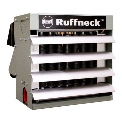
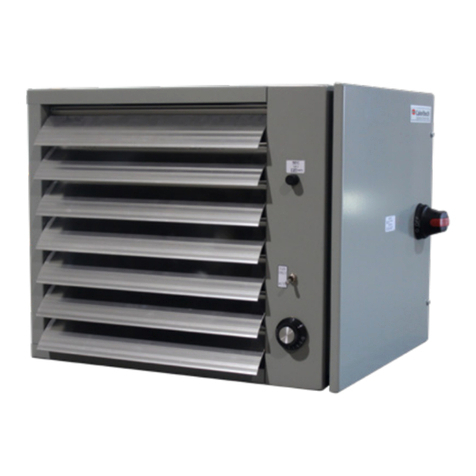
Ruffneck AH-12A User manual

1
Owner’s Manual
Advanced
Horizontal
Series
Heat-Exchanger Unit Heaters
ISO 9001
This manual covers installations, maintenance, repair and replacement parts.
WARNING!
READ ALL IMPORTANT NOTICES ON PAGE 3.
PLEASE ADHERE TO INSTRUCTIONS PUBLISHED IN THIS MANUAL.
Failure to do so may be dangerous and may void certain provisions of your warranty.
5475.Rev.9.02
Issue Date: April 2015
Printed in Canada
Runeck™ is a key brand of CCI Thermal Technologies Inc.
Copyright © 2015. All rights reserved.
APPROVED LOCATIONS
The Forced Air Heaters are CSA listed,
certified for the following locations:
Class I, Divisions 1 & 2, Groups C & D;
Class II, Division 1 & 2, Groups E, F, & G;
Class III, Division 1 & 2;
Temperature Code T3B 329˚F (165˚C)
(On Applicable Models Only)
For details of hazardous locations with potential for
explosion, refer to the Canadian Electrical Code, Part 1,
Section 18 or National Electrical Code articles 500-516.
®

2
For Heat-Exchanger Unit Heaters
HEATER MAINTENANCE CHECKLIST
Heater Model:
Date of Maintenance:
Comments:
Serial No.:
Maintenance Done By:
WARNING!
Heater should only be serviced by qualied personnel with heating equipment experience.
Disconnect heater from power supply before servicing heater. Lock the switch in the
“OFF” (open) position and/or tag the switch to prevent unexpected power application.
PERIODIC (before and as required during heating season)
1. CLEAN Finned Tubes
Fan
Fan Guard
Motor
Louvers
2. CHECK Motor for smooth, quiet operation
Louvers for proper angle and tightness
Electrical junction box cover for tightness
ANNUAL (before heating season)
Remove dust using compressed air. Do not spray with water or solvents.
1. ELECTRICAL
Check all terminal connections and conductors. Tighten loose connections. Conductors with
damaged insulation must be replaced.
2. MECHANICAL
Check for uid leakage. If any uid leakage occurs from the heater, remove it from service and
have the heat exchanger replaced. A factory supplied heat exchanger can be shipped in less
than a week from stock. Refer to the “Repair and Replacement” section for details.
Electrical junction box. Inside of enclosure must be clean, dry, and free of foreign materials.
Cover must be completely on and tight.
Check motor shaft bearing play. Replace motor if play is excessive or if motor does not run
quietly and smoothly. Motor bearings are permanently lubricated.
Check fan. Replace immediately if cracked or damaged.
Check louvers. Louver screws should be tight. Louvers are not to be closed more than 75˚
from horizontal.
Check the tightness of all hardware. All nuts and bolts, including mounting hardware, must be
tight.
TURN HEATER MOTOR ON FOR A MINIMUM OF 15 MINUTES. Check for air exiting heater
through louvers and smooth running of fan motor.
For assistance, please call
Toll Free: 1-800-661-8529 (24 hrs)
U.S. & Canada
Photocopy
this page
for reuse.

3
1. Read and follow the instructions in this manual.
2. Heaters are to be installed and serviced only
by qualified personnel experienced in electrical and
piping work.
3. Installation, piping, and wiring of he heater must
adhere to all applicable codes.
4. It is essential that any unit heater that will be used
in a hazardous (classified) location is equipped with
a electric motor approved for such service, and the
temperature of the heat transfer medium is below
the ignition temperature of the atmosphere.
5. Do not operate heater in atmospheres which are
corrosive to steel or aluminum, unless it has been
coated with a factory approved protective coating.
6. For steam service use only single-pass models.
Refer to model coding (page 7) for number of
passes in heat exchanger.
7. Refer to heat exchanger data plate for pressure
and temperature limits.
8. Heater must be kept clean. When operating in
a dirty environment, regularly clean the finned
tubes, fan and fan guard. Follow the recommended
maintenance procedures. Refer to the “Heater
Maintenance Checklist” section for details.
9. Use factory approved replacement parts only.
10. If there are any questions or concerns regarding
the heater, contact the factory. Refer to the last
page of this manual for details.
WARRANTY WILL BE VOID
IF INSTRUCTIONS ARE NOT FOLLOWED
INSTALLATION
The installation instructions provide a general guideline for the installation and wiring of the heater.
All applicable codes must be adhered to.
MECHANICAL
LOCATION
1. For optimum heating, the heaters should be installed as
follows:
a. There are no obstructions that may impede the heater’s
air inlet or discharge.
b. The air discharge is directed into open areas and not at
occupants.
c. The air discharge is not directed at a thermostat.
d. The air discharge is directed across areas of heat loss,
such as doors and windows (see Figure 1).
e. The air discharge is directed along, and at a slight angle
towards, exterior walls (see Figure 1).
f. If equipment freeze protection is important, direct air
discharge at equipment.
g. Air discharge streams support each other and create a
circular air flow. It is not required that the heater’s air
throw reaches the next heater.
h. For warehouses or large workshops it may be
acceptable to use fewer, larger heaters.
- 3 -
FIGURE 1
IMPORTANT NOTICES
WARNING:
Read and adhere to the following. Failure to do so may result in severe or fatal injury.
IMPORTANT NOTICES
WARNING!
Read and adhere to the following. Failure to do so may result in severe or fatal injury.
WARRANTY WILL BE VOID
IF INSTRUCTIONS ARE NOT FOLLOWED
1. Read and follow the instructions in this manual.
2. Heater to be used only in the hazardous locations indicated on the heater’s
data plate.
3. Heater is for dry indoor use only. Do not immerse in water. Do not store or
use in areas exposed to rain or snow.
4. Heater is to be connected and serviced only by a qualified electrician
experienced with hazardous location equipment.
5. Installation, piping, and wiring of he heater must adhere to all applicable
codes.
6. It is essential that any unit heater that will be used in a hazardous (classied)
location is equipped with a electric motor approved for such service, and the
temperature of the heat transfer medium is below the ignition temperature
of the atmosphere. Refer to applicable electrical codes for additional
information.
7. Disconnect heater from power supply at integral disconnect or fuse box
before opening enclosures or servicing heater. Lock the switch in the
“OFF” (open) position and/or tag the switch to prevent unexpected power
application. IF INTEGRAL DISCONNECT IS BEING SERVICED, verify that
power has been disconnected at fuse box or main panel. Lock the switch in
the “OFF” (open) position and/or tag the switch to prevent unexpected power
application.
8. Do not operate heater in atmospheres which are corrosive to steel or
aluminum, unless it has been coated with a factory approved protective
coating.
9. For steam service use only single-pass models. Refer to model coding (page
7) for number of passes in heat exchanger.
10. Refer to heat exchanger data plate for pressure and temperature limits.
11. Heater must be kept clean. When operating in a dirty environment, regularly
clean the nned tubes, fan and fan guard. Follow the recommended
maintenance procedures. Refer to the “Heater Maintenance Checklist”
section for details.
12. Use factory approved replacement parts only.
13. If there are any questions or concerns regarding the heater, contact the
factory. Refer to the last page of this manual for details.
14. HVAC uids must be non-ammable, non-compressable, non-explosive &
non-toxic.
15. Do not operate the heater with any of the louvers fully closed or overriding
their stops.
16. Do not operate heater in ambient temperatures above 104°F (40°C).
17. See applicable electrical codes for seal requirements in eld installed
conduits. Factory installed conduits require no further sealing.
18. Base of the heater is to be mounted a minimum of 7.9 ft (2.4 m) above the
oor. Refer to the “Installation” section for details.
INSTALLATION
The installation instructions provide a general guideline for the installation and wiring of the heater.
All applicable codes must be adhered to.
MECHANICAL
LOCATION
1. For optimum heating, the heaters should be installed as
follows:
a. There are no obstructions that may impede the
heater’s air inlet or discharge.
b. The air discharge is directed into open areas and not
at occupants.
c. The air discharge is not directed at a thermostat.
d. The air discharge is directed across areas of heat
loss, such as doors and windows (see Figure 1).
e. The air discharge is directed along, and at a slight
angle towards, exterior walls (see Figure 1).
f. If equipment freeze protection is important, direct air
discharge at equipment.
g. Air discharge streams support each other and create
a circular air ow. It is not required that the heater’s
air throw reaches the next heater.
h. For warehouses or large workshops it may be
acceptable to use fewer, larger heaters.

4
FIGURE 3
FIGURE 2
AH-24B Tandem
A in. 52-15/16
mm 1345
B in. 31-1/2
mm 800
C in. 4-13/16
mm 122
D in. 7-7/16
mm 189
E in. 24-3/16
mm 615
F in. 58-1/4
mm 1480
G in. 9/16
mm 14.3
H in. 36-7/8
mm 937
I in. 2-1/16
mm 53
J in. 5/8
mm 16
K in. 59-1/2
mm 1512
DIM AH-12A AH-16A AH-20A AH-24A
A in 15-13/16 19-13/16 23-13/16 27-7/8
mm 401 503 605 707
B in 19-7/16 23-1/2 27-1/2 31-1/2
mm 494 596 698 800
C in 4-3/16 4-3/16 4-3/16 4-3/16
mm 107 107 107 107
D in 7-15/16 7-9/16 7-3/16 6-7/8
mm 201 192 183 174
E in 23-5/8 23-5/8 23-5/8 23-5/8
mm 600 600 600 600
F in 18-3/16 22-3/16 26-3/16 30-3/16
mm 462 564 665 766
G in 9/16 9/16 9/16 9/16
mm 14.3 14.3 14.3 14.3
H in 23-7/8 27-7/8 31-7/8 35-7/8
mm 606.5 708.5 809.5 911.5
I in 1-9/16 1-9/16 1-9/16 1-9/16
mm 39 39 39 39
J in 5/8 5/8 5/8 5/8
mm 16 16 16 16
K
in 27-1/2 31-5/8 35-1/2 39-5/8
mm 698.5 802.5 903 1005
L in. 65-1/2
mm 1662.5
MOUNTING
1. The unit heater is designed to be installed in an upright and
level position. However, it may be installed in any position
provided that for steam service the inlet is above the outlet
and the bottom of the heat exchanger drains towards the
outlet.
2. Heater cabinets are designed to be mounted from the top or
bottom using 1/2” (14 mm) bolts. For heater dimensions, see
Figure 2 for single fan or Figure 3 for 24” tandem.
3. The mounting structure must be strong enough to:
a. support the heater’s weight (refer to the specication
section),
b. provide sucient stiness to prevent excessive
vibration, and
c. withstand abusive situations such as transportable
installations.
4. For ease of installation, a variety of mounting kits are
available from the factory.
MOUNTING HEIGHTS
1. The base of the heater is to be elevated a minimum of 7.9
ft (2.4 m) above the oor.
2. Heaters maybe mounted at higher elevations and still
provide warm air at the oor level. The maximum elevation
at which warm air will still reach the oor depends on site
and operation conditions.
3. Louvers can be adjusted to provide greater downward
deection of the discharge air. It is recommended that
louvers not be closed more than 75° from full open.
MOUNTING CLEARANCES
1. Leave at least 20” (500 mm) clearance between the rear of
the motor and the nearest obstruction.
2. Clearance equal to the height of the heater cabinet above,
or beneath, the cabinet is required for easy fan or motor
replacement.
TEMPERATURE CONTROL
1. If required, the unit heater’s output may be thermostatically
controlled by the following:
a. Airow through the heat exchanger can be turned on
and o by thermostatically controlling the fan motor.
Usually the ow of the heat transfer medium is
allowed to pass through the heat exchanger without
interruption. This is the most economical method of
controlling the heater.
b. Heat transfer medium ow may be controlled by a
thermostatic valve, while allowing the fan motor to run
continuously to circulate room air.
c. Absolute control of the heater output from the heat
exchanger will require that the fan and heat transfer
medium be shut o. Such control of the heater
output is possible by a thermostatic valve control in
combination with the thermostatic fan control.
FINAL INSPECTION
1. Before application of electrical power:
a. Check that all connections are secured and comply
with the applicable wiring diagram (see Figure 7) and
code requirements.
b. Conrm the power supply is compatible with the data
plate rating on motor.
c. Remove any foreign objects from heater.
d. Ensure all electrical covers are well secured.
e. Ensure the fan rotates freely, ensure air exits through
louvers and the fan rotates counterclockwise when
viewed from the rear of the heater.

5
PIPING APPLICATIONS
1. For steam service use only single-pass heaters.
Refer to Model Coding Section for tube-side pass
designation.
2. Refer to figures 4-6 for typical piping applications.
3. To prevent condensate from entering the heater, slope
steam supply lines toward the steam main. In long
supply lines, drip traps may be needed.
4. For steam systems, use properly sized continuously
draining steam traps, such as float or thermostatic
types. Traps must be sized to handle start up and
operational flows.
5. If the condensate return main is above the heater
outlet or is pressurized, install a check valve after the
steam trap and a drain valve at the strainer to drain
the system during the off season.
6. Allow for efficient condensate drainage and sub-
cooling by maintaining the outlet pipe size between
the heater and steam trap. Provide at least a 10 inch
(254 mm) drop leg at condensate outlet.
7. In horizontal steam and condensate lines use
eccentric reducers only.
8. Allow for pipe expansion.
9. Eliminate pipe stress by adequately supporting all
piping. Do not rely on heater to support piping.
10. All piping must be properly sized for expected flow
rates.
11. For more piping information, consult industrial piping
handbooks.
12. Comply with all applicable piping codes.
- 5 -
Unit heater connection for
low-pressure steam,
open gravity or vacuum return system.
Unit heater connections to overhead steam
and return mains.
Unit heater connections to
overhead liquid mains
FIGURE 4
FIGURE 5 FIGURE 6
NOTES: 1. This piping arrangement is only for two-position-type control.
Modulating steam control may not provide sufficient pressure to
lift condensate to return main.
2. Do not use with fluids corrosive to steel.
3. Install using proper piping practices.
4. In horizontal pipe runs, use eccentric reducers only.
5. Use a properly sized steam trap.
NOTES: 1. For medium to high pressure systems a bucket or float trap
must be used.
2. Do not use with fluids corrosive to steel.
3. Install using proper piping practices.
4. In horizontal pipe runs, use eccentric reducers only.
5. Use a properly sized steam trap.
NOTES: 1. Do not use with fluids corrosive to steel.
2. Install using proper piping practices.
PIPING APPLICATIONS
1. For steam service use only single-pass heaters. Refer to
Model Coding Section for tube-side pass designation.
2. Refer to gures 4-6 for typical piping applications.
3. To prevent condensate from entering the heater, slope steam
supply lines toward the steam main. In long supply lines, drip
traps may be needed.
4. For steam systems, use properly sized continuously draining
steam traps, such as oat or thermostatic types. Traps must
be sized to handle start up and operational ows.
5. If the condensate return main is above the heater outlet or is
pressurized, install a check valve after the steam trap and a
drain valve at the strainer to drain the system during the o
season.
6. Allow for ecient condensate drainage and subcooling by
maintaining the outlet pipe size between the heater and
steam trap. Provide at least a 10 inch (254 mm) drop leg at
condensate outlet.
7. In horizontal steam and condensate lines use eccentric
reducers only.
8. Allow for pipe expansion.
9. Eliminate pipe stress by adequately supporting all piping. Do
not rely on heater to support piping.
10. All piping must be properly sized for expected ow rates.
11. For more piping information, consult industrial piping
handbooks.
12. Comply with all applicable piping codes.

6
MOTOR WIRING DIAGRAMS
CAUTION
Installation must be done by qualified personnel, and comply with local electrical codes.
For internal wiring of control devices and starters,
consult device manufacturer. The thermostat must have an electrical rating
equal to or exceeding the rating of the control device. For wiring of the fan motor, refer to diagram on
the motor. These wires must be connected in series with the motor control circuit.
FIGURE 7
- 6 -
MOTOR WIRING DIAGRAMS
CAUTION
Installation must be done by qualied personnel, and comply with local electrical codes.
For internal wiring of control devices and starters,
consult device manufacturer. The thermostat must have an electrical rating
equal to or exceeding the rating of the control device. For wiring of the fan motor, refer to diagram on
the motor. These wires must be connected in series with the motor control circuit.
MOTOR WIRING DIAGRAMS
CAUTION
Installation must be done by qualified personnel, and comply with local electrical codes.
For internal wiring of control devices and starters,
consult device manufacturer. The thermostat must have an electrical rating
equal to or exceeding the rating of the control device. For wiring of the fan motor, refer to diagram on
the motor. These wires must be connected in series with the motor control circuit.
FIGURE 7
- 6 -
WIRING DIAGRAM FOR BUILT-IN DISCONNECT SWITCH HEATERS
SINGLE PHASE Tandem Motor Unit
SINGLE PHASE
Single Motor Unit
THREE PHASE
Tandem Motor Unit
THREE PHASE

7
MODEL CODING
Base Model
Series Fan Heat Exchanger Cabinet Motor
A 1 1 A
AH 12A A 1 A 1
FAN SIZE
12” (305 mm) DIA 12A
16” (406 mm) DIA 16A
20” (508 mm) DIA 20A
24” (610 mm) DIA 24A
24” (610 mm) tandem 24B
A = Standard single fan
B = Standard dual fan
FAN SIZE
TUBING
WALL
THICKNESS
ROWS
FINNING
FINS/
INCH
MATERIAL
TYPE
5/8” (16 mm) .065” (1.7 mm) 3 10 AL TW A
1” (25 mm) .083” (21 mm) 2 9 AL EX B
1” (25 mm) .135” (3.4 mm) 2 5 AL EX C
TW = Tension Wound
EX = Extruded AL = Aluminum
PASSES
1 Pass 1
3 Passes 3
5 Passes 5
7 Passes 7
CONNECTIONS
1½” NPT Male Sch. 40 A
1½” (40 mm) 300# RF ange B
2” NPT Male Sch. 80 C
2” (50 mm) 300# RF ange D
EXCHANGER COATINGS
Heat resistant aluminum paint 1
Heresite® phenolic coating 2
CABINET MATERIAL
AEpoxy powder coated carbon steel
B Heresite® phenolic coated carbon steel
DISCHARGE TYPE
12-way aluminum louvres
2Nozzle
3 4-way aluminum louvres
HEATER CERTIFICATION
1General Purpose
2X-proof Motor Only, groups C, D, E, F, & G
3 CSA Certied Heater
MOTOR ELECTRICAL
SPECIFICATIONS
VOLTS PHASE HERTZ
A115 160
B 208 160
C208 3 60
D230 160
E230 3 60
F 460 160
G 460 3 60
H575 3 60
I 220 1 50
J380 3 50
K440 350
NOTE:
Runeck™ utilizes Doerr/Emerson/Baldor as our standard
motor. Specifying any other O.E.M. motor may result in
longer lead times. All heat exchangers are registered to CRN
OH10951.2C.
They are approved for use in all provinces and territories in
Canada.
Heresite® coated exchangers and cabinets: contact factory for
quote.
Louvres and fan blades are also Heresite® coated.
Contact factory for shipping lead time.
Motor designed to be used at rated voltage with tolerances of
±15%.
Motor may be marked 230V, but is suitable for 208V operation.
Tandem configuration not available on AV models.
460 1 phase motors are only certified for groups D, F & G
Only available in 16” (406 mm) and larger units
Only available in 24” (610 mm) and larger units
Built-in Disconnect only available with CSA Certified heater
D
Built-in
Disconnect
Switch

8
REPAIR & REPLACEMENT
WARNING
Heater should only be serviced by qualified
personnel with heating equipment experience.
Disconnect heater from power supply before
repairing heater. Lock the switch in the
off (open) position and/or tag the switch to
prevent unexpected power application.
Heater surfaces may be hot.
1. After repairing any component:
a. Check that electrical connections are correct and
secure.
b. Remove any foreign material from enclosures,
c. Install and secure all covers.
d. Ensure that all fasteners are tight.
e. Remove all foreign objects from heater.
f. Ensure air exits through louvers and fan rotates
counterclockwise when viewed from rear of heater
(see Figure 9).
MOTOR, FAN, AND
FAN GUARD
1. Remove bolts holding motor to the motor mount.
2. Remove the two piece fan guard assembly (see Figure 10).
3. Lift the motor assembly off the motor mount.
4. Before removing the fan, measure and record the location of
the fan hub on the motor shaft (see Figure 11). If fan is difficult
to remove, use a gear puller on the fan hub.
5. To reassemble, position fan on motor shaft and tighten set
screws.
6. Place motor assembly onto motor mount and fasten the fan
guard to cabinet.
7. Center fan in shroud opening. Leave approximately 1/16” to
3/16” (1.6 to 4.8 mm) gap between the motor and fan guard.
(see Figure 8).
8. Bolt motor to motor mount. Manually spin the fan blade to
ensure it rotates freely before applying power.
9. Air must exit through louvers and fan must rotate
counterclockwise when viewing from the rear of the heater
(see Figure 9).
- 8 -
FIGURE 9
FIGURE 10
FIGURE 11
FIGURE 8 FIGURE 12
1/16” to 3/16”
(1.6 to 4.8 mm)
Support
back of
heater
Fan
rotation
Air
intake
Core
Bolts
Motor -
mount
Bolts
REPAIR & REPLACEMENT
WARNING
Heater should only be serviced by qualied
personnel with heating equipment experience.
Disconnect heater from power supply before
repairing heater. Lock the switch in the
o (open) position and/or tag the switch to
prevent unexpected power application.
Heater surfaces may be hot.
1. After repairing any component:
a. Check that electrical connections are correct and secure.
b. Remove any foreign material from enclosures,
c. Install and secure all covers.
d. Ensure that all fasteners are tight.
e. Remove all foreign objects from heater.
f. Ensure air exits through louvers and fan rotates
counterclockwise when viewed from rear of heater (see
Figure 9).
MOTOR, FAN, AND FAN GUARD
1. Remove bolts holding motor to the motor mount.
2. Remove the two piece fan guard assembly (see Figure 10).
3. Lift the motor assembly o the motor mount.
4. Before removing the fan, measure and record the location of the
fan hub on the motor shaft (see Figure 11). If fan is dicult to
remove, use a gear puller on the fan hub.
5. To reassemble, position fan on motor shaft and tighten set
screws.
6. Place motor assembly onto motor mount and fasten the fan
guard to cabinet.
7. Center fan in shroud opening. Leave approximately 1/16” to
3/16” (1.6 to 4.8 mm) gap between the motor and fan guard.
(see Figure 8).
8. Bolt motor to motor mount. Manually spin the fan blade to
ensure it rotates freely before applying power.
9. Air must exit through louvers and fan must rotate
counterclockwise when viewing from the rear of the heater (see
Figure 9).

9
Support back
of heater
HEAT EXCHANGER REMOVAL OF
SINGLE- MOTOR UNIT HEATER
1. Remove unit heater from its mounted location and
lower to a stable working surface.
2. Remove all louver blades from the front of
the cabinet.
3. Remove the left fan guard and left cabinet
side panel as described below. If the heat exchanger
has flanged connections, also remove the top
cabinet panel.
4. Support the weight of the heat exchanger by the
piping connection while removing the four core bolts
that fasten the heat exchanger to the cabinet. (See
figure 9). Allow heat exchanger to rest on the bottom
of the cabinet.
5. Remove the two bolts holding the motor mount to
the left side of the cabinet. Support motor mount while
removing these two bolts. Once cabinet side has
been removed, reinsert the bolts in the motor
mount. Place a support under the motor mount to
prevent the cabinet from rolling over during heat
exchanger removal (see Figure 12).
6. With the cabinet side removed and motor mount
supported, slide heat exchanger out of the cabinet.
(see Figure 13). On larger units, assistance may be
necessary due to the weight of the heat exchanger.
7. To install heat exchanger into cabinet, reverse order
of heat exchanger removal procedure.
HEAT EXCHANGER REMOVAL OF
DOUBLE-MOTOR UNIT HEATER
(Due to the weight of the heat exchanger, an assistant is
recommended to help with the following procedure.)
1. Remove unit heater from its mounted location and
lower to a stable work surface. To prevent damage to
the bottom piping connection, do not rest heater on
connection while servicing.
2. Remove all louvers from the front of the cabinet.
3. Remove the top cabinet panel by removing the four
bolts in the corners of the top panel and the fasteners
along the top of the shrouds (see Figure 14).
4. Have an assistant support the weight of the heat
exchanger while removing the eight bolts that fasten
the heat exchanger to the cabinet (see Figure 15).
Once the bolts on one side are removed, lower that
side of the heat exchanger to rest on the bottom of
the cabinet. Place a support under the motor mount
of the cabinet to prevent the cabinet from rolling over
during heat exchanger removal (see Figure 14).
5. Loosen cabinet side panel fasteners but do
not remove. If the heat exchanger has flanged
connections also remove the left side panel.
6. Lift the heat exchanger up and out through the front
of the cabinet (see Figure 16).
7. To install heat exchanger procedure, reverse the
order of heat exchanger removal procedure.
- 9 -
FIGURE 15
FIGURE 14
FIGURE 16
FIGURE 13
HEAT EXCHANGER REMOVAL OF
SINGLE- MOTOR UNIT HEATER
1. Remove unit heater from its mounted location and lower to a
stable working surface.
2. Remove all louver blades from the front of the cabinet.
3. Remove the left fan guard and left cabinet side panel as
described below. If the heat exchanger has anged connections,
also remove the top cabinet panel.
4. Support the weight of the heat exchanger by the piping
connection while removing the four core bolts that fasten
the heat exchanger to the cabinet. (See gure 9). Allow heat
exchanger to rest on the bottom of the cabinet.
5. Remove the two bolts holding the motor mount to the left side
of the cabinet. Support motor mount while removing these two
bolts. Once cabinet side has been removed, reinsert the bolts
in the motor mount. Place a support under the motor mount
to prevent the cabinet from rolling over during heat exchanger
removal (see Figure 12).
6. With the cabinet side removed and motor mount supported,
slide heat exchanger out of the cabinet. (see Figure 13). On
larger units, assistance may be necessary due to the weight of
the heat exchanger.
7. To install heat exchanger into cabinet, reverse order of heat
exchanger removal procedure.
HEAT EXCHANGER REMOVAL OF
DOUBLE-MOTOR UNIT HEATER
(Due to the weight of the heat exchanger, an assistant is
recommended to help with the following procedure.)
1. Remove unit heater from its mounted location and lower to a
stable work surface. To prevent damage to the bottom piping
connection, do not rest heater on connection while servicing.
2. Remove all louvers from the front of the cabinet.
3. Remove the top cabinet panel by removing the four bolts in the
corners of the top panel and the fasteners along the top of the
shrouds (see Figure 14).
4. Have an assistant support the weight of the heat exchanger
while removing the eight bolts that fasten the heat exchanger
to the cabinet (see Figure 15). Once the bolts on one side are
removed, lower that side of the heat exchanger to rest on the
bottom of the cabinet. Place a support under the motor mount of
the cabinet to prevent the cabinet from rolling over during heat
exchanger removal (see Figure 14).
5. Loosen cabinet side panel fasteners but do not remove. If the
heat exchanger has anged connections also remove the left
side panel.
6. Lift the heat exchanger up and out through the front of the
cabinet (see Figure 16).
7. To install heat exchanger procedure, reverse the order of heat
exchanger removal procedure.

10
ITEM AH-12A AH-16A AH - 20A AH-24A AH-24B DESCRIPTION
15378 5382 5386 5390 5394 Panel,AH Top/Bottom
25376 5380 5384 5388 5392 Panel, AH Right Side
3 5379 5383 5387 5391 5391 Panel, AH Shroud
411284 5449 5450 5451 5451 Fan
54087 4088 4089 5396 5396 Fan Guard (half)
6*** *** *** *** *** Motor
73789 3789 3789 3789 3789 Bracket, Motor Mount Right
8 3785 3787 3787 5433 5433 Channel, Motor Mount
93788 3788 3788 3788 3788 Bracket, Motor Mount Left
10 5377 5381 5385 5389 5393 Panel, AH Left Side
11 ** ** ** ** ** Heat Exchanger
12 4075 4076 4077 5741 5742 Kit, Louver (c/w screws)
** Provide complete model and serial number of heater when ordering replacement heat exchanger.
*** Provide motor voltage, phase, horsepower and service classication when ordering replacement motor.
Note: For items not shown, contact factory.
PARTS LIST
AH - 12A, - 16A, - 20A, and - 24A
AH - 24B
FIGURE 17
FIGURE 18

11
XS40
KIT, XS40 DISC SWTCH ASSM
ANGULAR
CHK'D BY:
APP'D. BY:
SCALE:
DRN BY:
±
DWG NO.:
TITLE:
SYTELINE NO.: METRIC
TOLERANCE UNLESS NOTED OTHERWISE
DECIMAL FRACTIONAL
REVISION DESCRIPTION
REV. BYDATE
1/2° 0.005" 1/16" 1 mm
SHEET:
XS40
lbrauer 19 Dec 2013
±±±
SCALE
EDMONTON, ALBERTA
1 OF 1
6
1
2
1
10
1
1
1
7
1
9
1
4
2
5
1
8
2
3
1
11
1
12
1
Item Number Part Number Description Quantity
1 B16229-03 Terminal Box, X-max Series 2 1
212147 Disconnect Switch Handle 1
312241-02 Operating Shaft 1
4 B12334-01 Terminal Box Cover 2
5 B12676-07 Trolley, Disconnect Switch 1
611362 Bracket, Din Rail 1
712112 Switch, Disconnect 1
8 B12676-07 Terminal Block Ass'y 2
9 XHP100 Dry Seal Plug 1" NPT 1
10 11650 Mounting Bracket 1
11 Contact Manufactuer Cable, Teck-90HL 1
12 Contact Manufacturer Fitting, Teck Cable 1
ITEM Part Number DESCRIPTION QUANTITY
1B16229-03 Terminal Box, X-max Series 2 1
2 12147 Disconnect Switch Handle 1
3 12241-02 Operating Shaft 1
4B12334-01 Terminal Box Cover 2
5B12676-07 Trolley, Disconnect Switch 1
6 11362 Bracket, Din Rail 1
7 12112 Switch, Disconnect 1
8 B12676-07 Terminal Block Ass’y 2
9XHP100 Dry Seal Plug 1” NPT 1
10 11650 Mounting Bracket 1
11 Contact Manufacturer Cable, Teck-90HL 1
12 Contact Manufacturer Fitting, Teck Cable 1
XS40 Disconnect
FIGURE 19

12
GENERAL SPECIFICATIONS
Approvals Class I, Division 1 & 2, Groups C and D; Class II, Division 1 & 2, Groups E, F, G
CRN (Canada) - Steam and HVAC liquids only. - CRN OH10951.2C
Fan Three blade aluminum, steel spider and hub with 5/8” bore.
Fan Guard Two piece design with close wire spacing. 3/8” diameter probe will not enter.
Epoxy coated to match cabinet color.
Mounting Holes 9/16” diameter holes, two at top and two at bottom of heater.
Cabinet Material 14 gauge (0.075”) steel. Epoxy coated with ve-stage pretreatment, including iron phosphate.
Motors CSA and/or UL listed 1725 RPM permanently lubricated ball bearing type with rigid base.
Explosion-proof or general purpose construction. All 50 and 60 hertz, standard voltages
available.
Louver Blades Anodized extruded aluminum.
Header Material 3/16” (0.187”) carbon steel.
Fluid Connections 1-1/2” NPT male Sch. 40, 1-1/2” 300# RF anges, 2” NPT Male Sch. 80 or 2” 300# RF ange
Max. Operating Press. 450 psi. Refer to Model Specications below for restrictions.
Max. Operating Temp. 650˚F.
Finned Tubes • 5/8” outside diameter (16 gauge, 0.065” wall thickness) carbon steel tubes.
Tension wound aluminum ns @ 10 ns per inch, or
• 1” outside diameter (14 gauge, 0.083” wall thickness) carbon steel tubes.
Extruded aluminum ns @ 9 ns per inch, or
• 1” outside diameter (10 gauge, 0.135” wall thickness) carbon steel tubes.
Extruded aluminum ns @ 5 ns per inch.
Optional Disconnect XS40 Disconnect Switch suitable for single and three phase motors.
Base Model Air
Delivery**
Air Throw at
15 psi steam
Motor***
Requirements
Tube
Passes
Max
Allowable
Pressure
for Steam
Units†
Net
Weight Δ
Shipping
Weight Δ
Net
Weight Δ
with Disconnect
Switch
Shipping
Weight Δ
with Disconnect
Switch
AH-12A-A__ 1150 CFM 28’ (8.5m) 1/2 HP 1 or 3 150 psi 102 lbs. 142 lbs. 117 lbs. 167 lbs.
AH-12A-B__ 1160 CFM 28’ (8.5m) 1/2 HP 1 or 3 200 psi 107 lbs. 147 lbs. 122 lbs. 172 lbs.
AH-12A-C1 1030 CFM 28’ (8.5m) 1/2 HP 1300 psi 118 lbs. 158 lbs. 133 lbs. 183 lbs.
AH-16A-A__ 1840 CFM 40’ (12.2m) 1/2 HP 1, 3 or 5 135 psi 127 lbs. 167 lbs. 142 lbs. 192 lbs.
AH-16A-B__ 1780 CFM 40’ (12.2m) 1/2 HP 1, 3 or 5 150 psi 138 lbs. 178 lbs. 153 lbs. 203 lbs.
AH-16A-C1 1840 CFM 40’ (12.2m) 1/2 HP 1395 psi 153 lbs. 193 lbs. 168 lbs. 218 lbs.
AH-20A-A__ 2930 CFM 40’ (12.2m) 1/2 HP 1, 3 or 5 180 psi 155 lbs. 205 lbs. 180 lbs. 230 lbs.
AH-20A-B__ 2700 CFM 40’ (12.2m) 1/2 HP 1, 3 or 5 140 psi 170 lbs. 220 lbs. 195 lbs. 245 lbs.
AH-20A-C1 3000 CFM 40’ (12.2m) 1/2 HP 1 450 psi 195 lbs. 245 lbs. 210 lbs. 270 lbs.
AH-24A-A__ 3890 CFM 40’ (12.2m) 1/2 HP 1, 3, 5 or 7 165 psi 189 lbs. 249 lbs. 204 lbs. 274 lbs.
AH-24A-B__ 3640 CFM 40’ (12.2m) 1/2 HP 1, 3, 5 or 7 190 psi 212 lbs. 272 lbs. 227 lbs. 297 lbs.
AH-24A-C1 3490 CFM 40’ (12.2m) 1/2 HP 1335 psi 258 lbs. 318 lbs. 273 lbs. 343 lbs.
AH-24B-A__ 7650 CFM 65’ (19.8m) (2) 1/2 HP 1, 3, 5 or 7 235 psi 313 lbs. 413 lbs. 338 lbs. 438 lbs.
AH-24B-B__ 7420 CFM 65’ (19.8m) (2) 1/2 HP 1, 3, 5 or 7 295 psi 376 lbs. 476 lbs. 391 lbs. 501 lbs.
AH-24B-C1 6690 CFM 65’ (19.8m) (2) 1/2 HP 1 450 psi 440 lbs. 540 lbs. 455 lbs. 565 lbs.
* See page 7 for model coding.
** At 70˚F and sea level.
*** Runeck reserves the right to substitute motors of higher horsepower.
Δ Add 12 lbs to anged units.
† Pressure restrictions are for CSA Certified heaters only.
MODEL SPECIFICATIONS

13
NOTES

14
LIMITED 1-YEAR WARRANTY
CCI Thermal Technologies Inc. warrants all Runeck™ Advanced Horizontal Series Unit Heaters
against defects in materials and workmanship for a period of one (1) year from date of purchase
on the following terms:
1. We will provide replacement parts free of charge as necessary to restore any unit to normal
operating condition, provided that the inoperative parts be returned to us freight prepaid and
that the replacement parts be accepted freight collect.
2. The complete heater may be returned to our plant for repair or replacement (at our discretion),
provided that all related freight costs be borne by the customer.
3. Corrosion and contamination by dirt, dust, etc. will not be considered as defects and, therefore,
are not warrantable.
4. The heater must not be modied in any way.
5. The heater must be installed, used and stored only in accordance with the owner’s manual
and placarded information. This warranty shall be limited to the actual equipment involved
and, under no circumstances, shall include or extend to installation or removal costs, or to
consequential losses or damages.
PLEASE ADHERE TO INSTRUCTIONS PUBLISHED IN THIS MANUAL.
Failure to do so may be dangerous and may void certain provisions of your warranty.
For further assistance, please call:
24-Hour Hotline: 1-800-661-8529
(U.S. and Canada)
Please have model and serial numbers available before calling.
5918 Roper Road
Edmonton, Alberta T6B 3E1 Canada
Phone: (780) 466-3178
Fax: (780) 468-5904
www.ccithermal.com

15
Chauffages pour les environnements les plus rigoureux
MC
Guide d’utilisation
Aérothermes à échangeur de chaleur
Série AH
Advanced Horizontal
ISO 9001
Ce guide traite de l’installation, de la maintenance, de la réparation et des pièces.
AVERTISSEMENT
LIRE TOUS LES AVIS IMPORTANTS À LA PAGE 3.
RESPECTER LES DIRECTIVES DU PRÉSENT GUIDE
pour éviter tout danger ainsi que l’annulation de certaines dispositions de la garantie.
N° de pièce 5475.Rev.9.02 Date d’émission : Avril 2015
Imprimé au Canada
RuneckTM est une marque déposée. Copyright © 2015. Tous droits réservés.
EMPLACEMENTS APPROUVÉS
Les systèmes de chauffage à air chaud pulsé sont
homologués CSA pour les emplacements suivants :
Catégorie I, divisions 1 et 2, groupes C et D;
Catégorie II, divisions 1 et 2, groupes E, F et G;
Catégorie III, divisions 1 et 2;
Classe de température T3B 329 ˚F (165 ˚C)
(Uniquement sur les modèles applicables)
Pour plus de détails endroits dangereux avec des risques
d’explosion, se référer au Code canadien de l’électricité,
Partie 1, Section 18 ou des articles 500 à 516 du Code
électrique national.
®

16
Pour aérothermes à échangeur de chaleur
LISTE DE CONTRÔLE DE MAINTENANCE DE L’AÉROTHERME
Modèle d’aérotherme :
Date de maintenance :
Commentaires :
N° de série :
Maintenance faite par :
AVERTISSEMENT
Seul un personnel qualié et expérimenté avec les appareils de chauage peut eectuer la
maintenance de cet aérotherme. Couper l’alimentation électrique de l’aérotherme avant d’eectuer
la maintenance de l’aérotherme. Régler l’interrupteur à la position OFF (arrêt) ou l’étiqueter pour
empêcher tout branchement accidentel.
PÉRIODIQUE (avant ou, au besoin, pendant la période de chaue)
1. NETTOYER Tuyaux à ailettes
Ventilateur
Grille de protection
Moteur
Lames déectrices
2. VÉRIFIER Fonctionnement silencieux du moteur
L’angle et le serrage des lames déectrices
L’étanchéité du couvercle de la boîte de
jonction électrique
ANNUELLE (avant la période de chaue)
Enlever la poussière au jet d’air comprimé. Ne pas vaporiser d’eau ni de solvants.
1. ENTRETIEN ÉLECTRIQUE
Vérier tous les conducteurs et les bornes de connexion. Serrer les connexions lâches.
Remplacer les conducteurs dont l’isolation est endommagée.
2. ENTRETIEN MÉCANIQUE
Vérier s’il y a des fuites de uide. S’il y a des fuites de uide de l’aérotherme, le retirer du
système et remplacer l’échangeur de chaleur. Les échangeurs de chaleur tenus en inventaire
peuvent être expédiés en moins d’une semaine. Pour plus de détails, consulter la section
« Réparation et remplacement ».
Boîte de jonction électrique. L’intérieur de la boîte de jonction doit être propre, sec et exempt de
corps étrangers. Le couvercle doit être complètement fermé et étanche.
Vérier les roulements de l’arbre du moteur. Remplacer le moteur s’il y a jeu excessif des
roulements d’arbre du moteur ou si le moteur ne tourne pas silencieusement. Les roulements du
moteur sont lubriés en permanence.
Vérier le ventilateur. Si le ventilateur est ssuré ou endommagé, le remplacer immédiatement.
Vérier les lames déectrices. Les vis des lames déectrices doivent être serrées. L’angle de
fermeture des lames déectrices ne doit pas dépasser 75° à partir de l’horizontale.
Vérier le serrage de toutes les attaches. Tous les boulons, écrous, vis et pièces
d’assemblage, doivent être bien serrés.
FAIRE FONCTIONNER LE MOTEUR DE L’AÉROTHERME PENDANT AU MOINS 15
MINUTES. S’assurer que l’air sort par les lames déectrices et que le moteur tourne
silencieusement.
Pour de l’assistance, composer le
numéro sans frais 1-800-661-8529
(24 heures sur 24) (Canada et É.-U.)
Chauffages pour les environnements les plus rigoureux
MC
Photocopier
cette page
pour la
réutiliser.

17
LA GARANTIE SERA ANNULÉE
SI CES DIRECTIVES NE SONT PAS SUIVIES
INSTALLATION
Les directives d’installation donnent une idée générale de l’installation et du câblage de l’aérotherme.
Se conformer à tous les codes en vigueur.
INSTALLATION MÉCANIQUE
POSITIONNEMENT
1. Pour un chauffage optimal, installer l’aérotherme
comme suit :
a. S’assurer qu’il n’y a aucune obstruction nuisant à
l’arrivée d’air ou à la sortie d’air de l’aérotherme.
b. Diriger la sortie d’air vers les espaces ouverts et non
vers les personnes.
c. Ne pas diriger la sortie d’air vers un thermostat.
d. Diriger la sortie d’air vers les zones de déperdition
thermique, comme les portes ou les fenêtres
(voir la figure 1).
e. Diriger la sortie d‘air sur un petit angle le long des
murs extérieurs (voir la figure 1).
f. Pour protéger un équipement contre le gel, la sortie
d’air doit être dirigée vers cet équipement.
g. Les sorties d’air doivent être complémentaires
et créer un courant circulaire. Il n’est pas nécessaire
que le jet d’air d’un aérotherme atteigne le prochain
aérotherme.
h. Pour les entrepôts ou ateliers à grande surface,
on peut utiliser des aérothermes plus gros et moins
nombreux.
- 3 -
FIGURE 1
1. Lire et suivre les directives du présent guide.
2. L’installation et la maintenance de cet aérotherme
ne doivent être effectuées que par les personnes
qualifiées dans les travaux électriques et de
tuyauterie.
3. L'installation de l'aérotherme, de la tuyauterie et
du câblage doivent être conformes aux codes en
vigueur.
4. Il est essentiel que tout aérotherme devant être
utilisé dans un emplacement (classé) dangereux
soit équipé d’un moteur électrique certifié pour
utilisation dans les emplacements dangereux,
et que la température du fluide caloporteur soit
inférieure à la température d’inflammation de
l’atmosphère.
5. Ne pas faire fonctionner l’aérotherme dans
des environnements corrosifs pour l’acier ou
l’aluminium, sauf si l'aérotherme est enduit d’un
revêtement protecteur certifié par le fabricant.
6. Pour utilisation avec la vapeur, n'utiliser que les
modèles à une seule passe. Vérifier le codage de
modèle pour connaître le nombre de passes de
l’échangeur de chaleur.
7. Vérifier les limites de pression et de température
indiquées sur la plaque signalétique de l'échangeur
de chaleur.
8. L’aérotherme doit être maintenu propre. S’il est
utilisé dans un environnement propice à la saleté,
nettoyer périodiquement les tuyaux à ailettes, le
ventilateur et la grille de protection. Suivre les
procédures de maintenance recommandées. Pour
plus de détails, consulter la section « Liste de
contrôle de maintenance de l’aérotherme. »
9. N’utiliser que les pièces de rechange originales du
fabricant.
10. Pour toute question concernant l'aérotherme,
communiquer avec le fabricant (voir la dernière
page de ce guide).
AVIS IMPORTANTS
AVERTISSEMENT :
Lire et respecter les directives suivantes afin d’éviter tout risque de blessure grave ou mortelle.
AVIS IMPORTANTS
AVERTISSEMENT :
Lire et respecter les directives suivantes an d’éviter tout risque de blessure grave ou mortelle.
LA GARANTIE SERA ANNULÉE
SI CES DIRECTIVES NE SONT PAS SUIVIES
1. Veiller à lire et suivre les instructions du présent manuel.
2. Le système de chauage ne doit être utilisé que dans les emplacements
dangereux indiqués sur la plaque signalétique du système.
3. Le système de chauage est destiné exclusivement à un usage à l’intérieur,
dans un endroit sec. Ne pas immerger dans l’eau. Ne pas stocker ou utiliser
dans des zones exposées à la pluie ou à la neige.
4. Le système de chauage ne doit être branché et entretenu que par un
électricien qualié et expérimenté en matière de matériel destiné à des
emplacements dangereux.
5. L’installation, la mise en place de la tuyauterie et le câblage du système de
chauage doivent être conformes à tous les codes applicables.
6. Il est essentiel que tout aérotherme destiné à être utilisé dans des
emplacements dangereux (classés) soit équipé d’un moteur électrique
homologué pour une utilisation de ce type, et que la température du uide
caloporteur soit inférieure à la température d’inammation de l’atmosphère. Se
référer aux codes de l’électricité applicables pour obtenir des renseignements
complémentaires.
7. Débrancher le système de chauage de la source d’alimentation électrique au
niveau du sectionneur intégré ou du coret à fusibles avant d’ouvrir les corets
ou de réparer le système de chauage. Verrouiller l’interrupteur en position «
ARRÊT » (ouvert) et/ou étiqueter ce dernier pour empêcher toute mise sous
tension inattendue. SI LE SECTIONNEUR INTÉGRÉ FAIT L’OBJET D’UNE
RÉPARATION, vérier que l’alimentation a été coupée au niveau du coret à
fusibles ou du panneau principal. Verrouiller l’interrupteur en position « ARRÊT
» (ouvert) et/ou étiqueter ce dernier pour empêcher toute mise sous tension
inattendue.
8. Ne pas utiliser le système de chauage dans des atmosphères qui ont un eet
corrosif sur l’acier ou l’aluminium, sauf s’il a été recouvert d’un revêtement
protecteur approuvé par le fabricant.
9. Pour une utilisation avec de la vapeur, utiliser exclusivement les modèles à un
passage. Se référer au codage du modèle (page 7) pour connaître le nombre
de passages de l’échangeur thermique.
10. Consulter la plaque signalétique de l’échangeur thermique pour connaître les
limites de pression et de température.
11. Le système de chauage doit être propre en permanence. Lorsque le système
de chauage est utilisé dans un environnement sale, nettoyer régulièrement
les tuyaux à ailettes, le ventilateur et la grille de protection. Suivre les
recommandations en matière de procédures d’entretien. Consulter la partie
intitulée « Liste de contrôle de l’entretien du système de chauage » pour
obtenir de l’information détaillée.
12. Utiliser uniquement les pièces de rechange approuvées par le fabricant.
13. Pour toute question ou inquiétude concernant ce système de chauage,
contacter le fabricant. Se reporter à la dernière page du présent manuel pour
obtenir des renseignements détaillés.
14. Les uides de chauage, de ventilation et de conditionnement d’air doivent être
non inammables, non compressibles, non explosifs et non toxiques.
15. Ne pas utiliser le système de chauage si l’une des grilles d’aération est
entièrement fermée ou dépasse sa butée.
16. Ne pas utiliser le système de chauage à des températures ambiantes
supérieures à 104 °F (40 °C).
17. Consulter les codes de l’électricité applicables pour connaître les exigences en
matière d’étanchéité dans les conduits installés sur place. Les conduits installés
en usine ne requièrent aucune mesure d’étanchéité supplémentaire.
18. La base du système de chauage doit être installée à une hauteur minimale de
7,9 pi (2,4 m) au-dessus du sol. Se reporter à la partie intitulée « Installation »
pour obtenir des renseignements détaillés.
INSTALLATION
Les directives d’installation donnent une idée générale de l’installation et du câblage de l’aérotherme.
Se conformer à tous les codes en vigueur.
INSTALLATION MÉCANIQUE
POSITIONNEMENT
1. Pour un chauage optimal, installer l’aérotherme
comme suit :
a. S’assurer qu’il n’y a aucune obstruction nuisant à l’arrivée
d’air ou à la sortie d’air de l’aérotherme.
b. Diriger la sortie d’air vers les espaces ouverts et non vers
les personnes.
c. Ne pas diriger la sortie d’air vers un thermostat.
d. Diriger la sortie d’air vers les zones de déperdition
thermique, comme les portes ou les fenêtres (voir la gure
1).
e. Diriger la sortie d‘air sur un petit angle le long des murs
extérieurs (voir la gure 1).
f. Pour protéger un équipement contre le gel, la sortie d’air
doit être dirigée vers cet équipement.
g. Les sorties d’air doivent être complémentaires et créer un
courant circulaire. Il n’est pas nécessaire que le jet d’air
d’un aérotherme atteigne le prochain aérotherme.
h. Pour les entrepôts ou ateliers à grande surface, on peut
utiliser des aérothermes plus gros et moins nombreux.

18
FIGURE 3
FIGURE 2
AH-24B Tandem
A po 52-15/16
mm 1345
B po 31-1/2
mm 800
C po 4-13/16
mm 122
D po 7-7/16
mm 189
E po 24-3/16
mm 615
F po 58-1/4
mm 1480
G po 9/16
mm 14.3
H po 36-7/8
mm 937
I po 2-1/16
mm 53
J po 5/8
mm 16
K po 59-1/2
mm 1512
DIM AH-12A AH-16A AH-20A AH-24A
A
po
15-13/16 19-13/16 23-13/16 27-7/8
mm 401 503 605 707
B
po
19-7/16 23-1/2 27-1/2 31-1/2
mm 494 596 698 800
C
po
4-3/16 4-3/16 4-3/16 4-3/16
mm 107 107 107 107
D
po
7-15/16 7-9/16 7-3/16 6-7/8
mm 201 192 183 174
E
po
23-5/8 23-5/8 23-5/8 23-5/8
mm 600 600 600 600
F
po
18-3/16 22-3/16 26-3/16 30-3/16
mm 462 564 665 766
G
po
9/16 9/16 9/16 9/16
mm 14.3 14.3 14.3 14.3
H
po
23-7/8 27-7/8 31-7/8 35-7/8
mm 606.5 708.5 809.5 911.5
I
po
1-9/16 1-9/16 1-9/16 1-9/16
mm 39 39 39 39
J
po
5/8 5/8 5/8 5/8
mm 16 16 16 16
K
po
27-1/2 31-5/8 35-1/2 39-5/8
mm 698.5 802.5 903 1005
L po 65-1/2
mm 1662.5
INSTALLATION
1. Cet aérotherme est conçu pour être installé en position
verticale et de niveau. Cependant, il peut être installé dans
n’importe quelle position, pourvu qu’en utilisant la vapeur,
l’entrée soit située au-dessus de la sortie, et que le bas de
l’échangeur de chaleur puisse drainer vers la sortie.
2. Le boîtier d’aérotherme doit être vissé par le haut ou par le
bas, en utilisant des boulons de 1/2 po (14 mm). Pour les
dimensions d’aérotherme, voir la gure 2 (unités à un seul
ventilateur) ou la gure 3 (unités de 24 po en tandem).
3. La structure de la surface d’installation doit être
susamment solide pour :
a. supporter le poids de l’aérotherme (voir la section «
Spécications »);
b. orir susamment de rigidité pour éviter les vibrations
excessives; et
c. résister aux chocs comme ceux subis dans les
installations mobiles des réchaueurs.
4. An de faciliter l’installation, plusieurs types de trousses de
montage sont disponibles auprès du fabricant.
HAUTEUR D’INSTALLATION
1. La base du système de chauage doit être installée à une
hauteur minimale de 7,9 pi (2,4 m) au-dessus du sol.
2. Les aérothermes peuvent être installés plus haut et fournir
quand même un apport d’air chaud au niveau du plancher.
La hauteur maximale à laquelle l’air chaud peut atteindre le
plancher dépend du lieu et des conditions de fonctionnement.
3. Les lames déectrices peuvent être ajustées pour projeter l’air
davantage vers le plancher. L’angle de fermeture des lames
déectrices ne doit pas dépasser 75° à partir de l’horizontale.
DÉGAGEMENT AUTOUR DE L’AÉROTHERME
1. Laisser un dégagement minimal de 20 po (500 mm) entre
l’arrière du moteur et l’obstacle le plus proche. 2. Un
dégagement équivalent à la hauteur totale de l’aérotherme est
requis, en haut ou en bas de l’aérotherme, pour permettre un
remplacement facile du ventilateur ou du moteur.
RÉGULATION DE TEMPÉRATURE
1. Au besoin, la régulation de température de l’aérotherme peut
être faite par thermostat, comme suit :
a. Le débit d’air à travers l’échangeur de chaleur peut être
coupé ou rétabli par commande thermostatique du moteur
de ventilateur. Habituellement, on laisse circuler le uide
caloporteur dans l’échangeur de chaleur sans interruption.
C’est la méthode de régulation d’aérotherme la plus
économique.
b. Le débit de uide caloporteur peut être commandé par
soupape thermostatique, permettant un fonctionnement
continuel du moteur de ventilateur pour maintenir la
circulation d’air dans le local.
c. Pour une régulation absolue de température de sortie
de l’aérotherme à partir de l’échangeur de chaleur, on
doit pouvoir arrêter le ventilateur et couper le débit de
uide caloporteur. Pour ce faire, on utilise une commande
à soupape thermostatique combinée à la régulation
thermostatique du ventilateur.
INSPECTION FINALE
1. Avant de mettre sous tension :
a. S’assurer que toutes les connexions sont serrées et que
l’installation est conforme au schéma de câblage pertinent
(voir la gure 7) et aux exigences des codes.
b. S’assurer que l’alimentation électrique est compatible
avec la puissance nominale de l’aérotherme, indiquée sur
la plaque signalétique du moteur.
c. Retirer tout corps étranger de l’intérieur de l’aérotherme.
d. S’assurer que tous les couvercles des boîtiers électriques
sont bien fermés.
e. S’assurer que le ventilateur tourne librement, que l’air sort
par les lames déectrices et que le ventilateur tourne en
sens inverse des aiguilles d’une montre, vu de l’arrière de
l’aérotherme.

19
INSTALLATION DE TUYAUTERIE
1. Pour utilisation sur système de vapeur, n'utiliser que des
aérothermes à une seule passe. Se référer à la section
« Codage de modèle » pour connaître le nombre de passes-
tube.
2. Les installations typiques de tuyauterie sont illustrées aux
figures 4 à 6.
3. Pour empêcher que le condensat n’entre dans l'aérotherme,
diriger la pente descendante du tuyau d’alimentation de vapeur
vers la conduite de vapeur principale. Pour les longs tuyaux
d’alimentation, des clapets d’évacuation peuvent être requis.
4. Pour les systèmes de vapeur, utiliser des purgeurs de
vapeur à drainage continu (ex. à flotteur ou thermostatiques),
dimensionnés selon les débits de vapeur en service et au
démarrage.
5. Si la conduite principale de retour du condensat est
pressurisée ou située plus haut que la sortie de l'aérotherme,
installer un clapet de non-retour après le purgeur de vapeur, et
un robinet de vidange à la crépine pour drainer le système en
période d’inutilisation.
6. Assurer un sous-refroidissement et drainage du condensat
efficaces en conservant le plein diamètre du tuyau de sortie
entre l'aérotherme et le purgeur de vapeur. Prévoir une
chute de hauteur minimale de 10 po (25,4 cm) à la sortie du
condensat de l’aérotherme.
7. Pour les conduites horizontales de vapeur et de condensat,
utiliser seulement des raccords réducteurs excentrés.
8. Prévoir de l’espace en raison de l’élargissement de la
tuyauterie.
9. Prévoir des supports adéquats pour réduire les contraintes
dans la tuyauterie. L'aérotherme ne doit pas servir de support.
10. Toute la tuyauterie doit être dimensionnée adéquatement en
fonction des débits prévus.
11. Pour plus de renseignements sur la tuyauterie, consulter les
manuels techniques de tuyauterie industrielle.
12. Respecter tous les codes de tuyauterie en vigueur.
- 5 -
Connexions de l'aérotherme aux systèmes de
vapeur basse pression, atmosphérique à
gravité ou à retour sous vide
Connexions de l'aérotherme aux conduites
suspendues de liquide caloporteur
Connexions de l'aérotherme aux conduites
suspendues de liquide caloporteur
FIGURE 4
FIGURE 5 FIGURE 6
REMARQUES : 1. Cet arrangement de tuyauterie est seulement pour la
ommande par tout ou rien. Avec une régulation modulante
de vapeur, la pression de vapeur pourrait être insuffisante
pour faire monter le condensat dans la conduite principale
de retour.
2.Ne pas utiliser avec des fluides corrosifs pour l’acier.
3.Suivre les normes d’installation de tuyauterie appropriées.
4.Pour les sections de tuyauterie horizontales, utiliser
seulement des raccords réducteurs excentrés.
5.Utiliser un purgeur de vapeur de dimension adéquate.
REMARQUES : 1. Pour les systèmes de moyenne à haute pression, un
purgeur à flotteur (ouvert ou fermé) doit être utilisé.
2. Ne pas utiliser avec des fluides corrosifs pour l’acier.
3. Suivre les normes d’installation de tuyauterie
appropriées.
4. Pour les sections de tuyauterie horizontales, n'utiliser
que des raccords réducteurs excentrés.
5. Utiliser un purgeur de vapeur de dimension adéquate.
REMARQUES : 1. Ne pas utiliser avec des fluides corrosifs pour l’acier.
2. Suivre les normes d’installation de tuyauterie
appropriées.
INSTALLATION DE TUYAUTERIE
1. Pour utilisation sur système de vapeur, n’utiliser que des
aérothermes à une seule passe. Se référer à la section «
Codage de modèle » pour connaître le nombre de passestube.
2. Les installations typiques de tuyauterie sont illustrées aux gures
4 à 6.
3. Pour empêcher que le condensat n’entre dans l’aérotherme,
diriger la pente descendante du tuyau d’alimentation de vapeur
vers la conduite de vapeur principale. Pour les longs tuyaux
d’alimentation, des clapets d’évacuation peuvent être requis.
4. Pour les systèmes de vapeur, utiliser des purgeurs de
vapeur à drainage continu (ex. à otteur ou thermostatiques),
dimensionnés selon les débits de vapeur en service et au
démarrage.
5. Si la conduite principale de retour du condensat est pressurisée
ou située plus haut que la sortie de l’aérotherme, installer un
clapet de non-retour après le purgeur de vapeur, et un robinet
de vidange à la crépine pour drainer le système en période
d’inutilisation.
6. Assurer un sous-refroidissement et drainage du condensat
ecaces en conservant le plein diamètre du tuyau de sortie
entre l’aérotherme et le purgeur de vapeur. Prévoir une chute de
hauteur minimale de 10 po (25,4 cm) à la sortie du condensat de
l’aérotherme.
7. Pour les conduites horizontales de vapeur et de condensat,
utiliser seulement des raccords réducteurs excentrés. 8. Prévoir
de l’espace en raison de l’élargissement de la tuyauterie.
9. Prévoir des supports adéquats pour réduire les contraintes dans
la tuyauterie. L’aérotherme ne doit pas servir de support.
10. Toute la tuyauterie doit être dimensionnée adéquatement en
fonction des débits prévus.
11. Pour plus de renseignements sur la tuyauterie, consulter les
manuels techniques de tuyauterie industrielle.
12. Respecter tous les codes de tuyauterie en vigueur.

20
SCHÉMAS DE CÂBLAGE DU MOTEUR
AVERTISSEMENT
L’installation de l'aérotherme doit être effectuée par un personnel qualifié et doit être conforme à
tous les codes électriques locaux. Pour le filage et câblage interne des appareils de régulation et
démarreurs, consulter les fabricants de ces appareils.
Le thermostat doit avoir des caractéristiques électriques équivalentes ou supérieures à celles des
appareils de régulation. Pour
le câblage du moteur de ventilateur, se référer à la plaque signalétique du moteur. Ces câbles et fils
doivent être connectés
en série avec l’unité de commande du moteur.
FIGURE 7
- 6 -
SCHÉMAS DE CÂBLAGE DU MOTEUR
AVERTISSEMENT
L’installation de l’aérotherme doit être eectuée par un personnel qualié et doit être conforme à
tous les codes électriques locaux. Pour le lage et câblage interne des appareils de régulation et
démarreurs, consulter les fabricants de ces appareils.
Le thermostat doit avoir des caractéristiques électriques équivalentes ou supérieures à celles des appareils
de régulation. Pour le câblage du moteur de ventilateur, se référer à la plaque signalétique du moteur.
Ces câbles et ls doivent être connectés en série avec l’unité de commande du moteur.
SCHÉMA DE CÂBLAGE DES SYSTÈMES DE CHAUFFAGE AVEC SECTIONNEUR INTÉGRÉ
SECTIONNEUR INTERRUPTEUR
DÉBRANCHER COSSE DE TERRE
MOTEUR COSSE DE TERRE
MOTEUR
SECTIONNEUR
MONOPHASÉ
SECTIONNEUR INTERRUPTEUR
DÉBRANCHER COSSE DE TERRE
MOTEUR COSSE DE TERRE
MOTEUR
SECTIONNEUR
TRIPHASÉ
SECTIONNEUR INTERRUPTEUR
DÉBRANCHER COSSE DE TERRE
MOTEUR COSSE DE TERRE
MOTEUR
MOTEUR COSSE DE TERRE
MOTEUR
SECTIONNEUR INTERRUPTEUR
DÉBRANCHER COSSE DE TERRE
MOTEUR COSSE DE TERRE
MOTEUR
MOTEUR COSSE DE TERRE
MOTEUR
SECTIONNEUR
MONOPHASÉ
SECTIONNEUR
TRIPHASÉ
MONOPHASÉ Appareil à moteur tandem
MONOPHASÉ
Appareil à moteur seul
TRIPHASÉ
Appareil à moteur tandem
TRIPHASÉ
SCHÉMAS DE CÂBLAGE DU MOTEUR
AVERTISSEMENT
L’installation de l'aérotherme doit être effectuée par un personnel qualifié et doit être conforme à
tous les codes électriques locaux. Pour le filage et câblage interne des appareils de régulation et
démarreurs, consulter les fabricants de ces appareils.
Le thermostat doit avoir des caractéristiques électriques équivalentes ou supérieures à celles des
appareils de régulation. Pour
le câblage du moteur de ventilateur, se référer à la plaque signalétique du moteur. Ces câbles et fils
doivent être connectés
en série avec l’unité de commande du moteur.
FIGURE 7
- 6 -
SECTIONNEUR INTERRUPTEUR
DÉBRANCHER COSSE DE TERRE
MOTEUR COSSE DE TERRE
MOTEUR
SECTIONNEUR
MONOPHASÉ
SECTIONNEUR INTERRUPTEUR
DÉBRANCHER COSSE DE TERRE
MOTEUR COSSE DE TERRE
MOTEUR
SECTIONNEUR
TRIPHASÉ
SECTIONNEUR INTERRUPTEUR
DÉBRANCHER COSSE DE TERRE
MOTEUR COSSE DE TERRE
MOTEUR
MOTEUR COSSE DE TERRE
MOTEUR
SECTIONNEUR INTERRUPTEUR
DÉBRANCHER COSSE DE TERRE
MOTEUR COSSE DE TERRE
MOTEUR
MOTEUR COSSE DE TERRE
MOTEUR
SECTIONNEUR
MONOPHASÉ
SECTIONNEUR
TRIPHASÉ
SECTIONNEUR INTERRUPTEUR
DÉBRANCHER COSSE DE TERRE
MOTEUR COSSE DE TERRE
MOTEUR
SECTIONNEUR
MONOPHASÉ
SECTIONNEUR INTERRUPTEUR
DÉBRANCHER COSSE DE TERRE
MOTEUR COSSE DE TERRE
MOTEUR
SECTIONNEUR
TRIPHASÉ
SECTIONNEUR INTERRUPTEUR
DÉBRANCHER COSSE DE TERRE
MOTEUR COSSE DE TERRE
MOTEUR
MOTEUR COSSE DE TERRE
MOTEUR
SECTIONNEUR INTERRUPTEUR
DÉBRANCHER COSSE DE TERRE
MOTEUR COSSE DE TERRE
MOTEUR
MOTEUR COSSE DE TERRE
MOTEUR
SECTIONNEUR
MONOPHASÉ
SECTIONNEUR
TRIPHASÉ
SECTIONNEUR INTERRUPTEUR
DÉBRANCHER COSSE DE TERRE
MOTEUR COSSE DE TERRE
MOTEUR
SECTIONNEUR
MONOPHASÉ
SECTIONNEUR INTERRUPTEUR
DÉBRANCHER COSSE DE TERRE
MOTEUR COSSE DE TERRE
MOTEUR
SECTIONNEUR
TRIPHASÉ
SECTIONNEUR INTERRUPTEUR
DÉBRANCHER COSSE DE TERRE
MOTEUR COSSE DE TERRE
MOTEUR
MOTEUR COSSE DE TERRE
MOTEUR
SECTIONNEUR INTERRUPTEUR
DÉBRANCHER COSSE DE TERRE
MOTEUR COSSE DE TERRE
MOTEUR
MOTEUR COSSE DE TERRE
MOTEUR
SECTIONNEUR
MONOPHASÉ
SECTIONNEUR
TRIPHASÉ
Other manuals for AH-12A
1
This manual suits for next models
3
Table of contents
Languages:
Other Ruffneck Heater manuals

Ruffneck
Ruffneck FE2 Series User manual

Ruffneck
Ruffneck FX4 Series Guide

Ruffneck
Ruffneck FR Series User manual

Ruffneck
Ruffneck RGE Series User manual

Ruffneck
Ruffneck CX1 ProVector Series Guide

Ruffneck
Ruffneck RGX152 User manual

Ruffneck
Ruffneck FX5 Series User manual

Ruffneck
Ruffneck FX5 Series Guide

Ruffneck
Ruffneck RGX Series Guide

Ruffneck
Ruffneck FX5-SD-220150-025 User manual