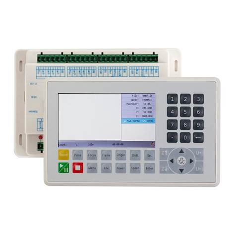
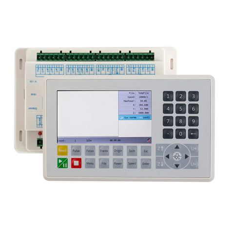
Ruida Technology RDC6432G User manual

RDC6432G control system user manual V1.1
SHENZHEN RUIDA TECHNOLOGY
RDC6432G
Laser cutting engraving control system user
manual
Read this manual before operation
The content include of electric connections and operating steps
Read the manual to operate the systems
RuiDa Technology Co., Ltd
Addr: 202-203,B-Block,Technology Building,NO.,1057 Nanhai
Avenue,Nanshan District,Shenzhen city,Guangdong
Province,P.R.China
Tel: 0755--26066687
Fax: 0755--26982287
E-mail: sales@rd-acs.com
Web: www.rd-acs.com

RDC6432G control system user manual V1.1
SHENZHEN RUIDA TECHNOLOGY
COPYRIGHT
All rights reserved.You may not reproduce, transmit, store in
a retrieval system or adapt thispublication, in any form or by any
means, without the prior written permissionof RuiDa, except as
allowed under applicable copyright laws. We have
identifiedwords that we consider as trademarks. Neither the
presence or absence oftrademark identifications affects the legal
status of any trademarks.

RDC6432G control system user manual V1.1
SHENZHEN RUIDA TECHNOLOGY
CERTIFICATION
DECLARATION
CE
The product has been certified by the CE (Commutate European) safety certification.
It has passed the corresponding conformity assessment procedure and the
manufacturer's declaration of conformity, in accordance with the relevant EU directive.
ROHS
This product has been certified by EU legislation (Restriction of Hazardous Substances)
Safety certification; comply with relevant EU environmental regulations.
FCC
This product has been certified by the Federal Communications Commission for safety,
Comply with us electronic safety regulations.

RDC6432G control system user manual V1.1
SHENZHEN RUIDA TECHNOLOGY
SAFETY INFORMATION
When using this system, please make sure the operation is correct and the usage is safe.
Some signs or text will be used to remind you to pay attention to the dangerous matters
and some important information.
Dangerous:
Indicates a serious danger. In the process of use, if the operation is
improper or the way of use is wrong, it may cause serious injury or
even death to the user. Please do not operate it easily until you have
made sure that the operation method is correct and the way of use is
correct.
Warning:
Danger.n the process of use, if the operation is improper or the use
is wrong, which may lead to the injury of the personnel, please do
not operate the personnel and related personnel easily, until ensure
the correct operation method and use method is correct before use.
Cautious:
Represents the potential risk of the product. In the process of use, if
the use method is wrong or improper operation, it may cause
damage to the product or some parts. Please do not use it until you
have made sure that the operation method is correct and the usage is
correct.
Important:
Represents important information to be paid attention to during the
use of the product.Please do not ignore this information, this
information will provide effective operational help.
This sign indicates laser radiation, which is usually posted on products
with laser output. Please be careful with laser and pay attention to
safety when using this kind of equipment.

RDC6432G control system user manual V1.1
SHENZHEN RUIDA TECHNOLOGY
Sign in、Devanning、Examine cargo
The product itself with plastic or metal shell, can protect the external electrical
components from damage. The products are packed in foam bags and anti-static bags. If
there is any external damage to the package, check the equipment and notify the carrier
and carrier in writing of the damage.
Inportant:
After receiving the product, please check whether the outer package is
intact, check whether the product is complete after unpacking and
whether all parts are intact. If any damage is found, please contact ruida
immediately.
Remove all cargo from package and keep packing material and wiring parts. Please take
care of the safety of the goods when unpacking them.After taking out the goods, please
check whether the parts are complete and intact. If any missing parts or damaged parts
are found, please contact ruida technology immediately.Do not install or debug the
equipment if any obvious damage is found.

RDC6432G control system user manual V1.1
SHENZHEN RUIDA TECHNOLOGY
Contents
Section 1 Overview.......................................................................................................................................1
1.1 RDC6432G Control System Introduction............................................................................................1
Section 2 Installation dimensions................................................................................................................ 2
2.1 Mainboard installation size................................................................................................................ 4
2.2 Panel mounting dimensions...............................................................................................................5
Section 3 Physical maps and interfaces.......................................................................................................6
3.1 Picture of mainboard......................................................................................................................... 7
3.2 Picture of panel.................................................................................................................................. 8
3.3 Control system electrical connection diagram.................................................................................. 9
Section 4 Mainboard Interface Signal Description.................................................................................... 10
4.1 Main power connector power......................................................................................................... 11
4.2 Mainboard and display connector HMI........................................................................................... 11
4.3 Udisk interface................................................................................................................................. 11
4.4 PC-USB interface.............................................................................................................................. 11
4.5 General/dedicated OUTPUT.............................................................................................................12
4.6 Dedicated/ General input interface INPUT......................................................................................13
4.7 Three-axis limit input interface LIMIT..............................................................................................13
4.8 X/Y/U Three-axis drive interface AXIS_X~AXIS_U............................................................................14
4.9 Laser power control interface..........................................................................................................15
Section 5 Examples of Laser Power Interface............................................................................................16
5.1 Overview.......................................................................................................................................... 17
5.2 Diagram of glass tube laser power connection............................................................................... 18
5.3 RF CO2 laser wiring diagram............................................................................................................ 19
Section 6 Example of Stepper Motor Driver Interface.............................................................................. 20
6.1 Overview.......................................................................................................................................... 21
6.2 Drive connection diagram................................................................................................................22
Section 7 IO Port Wiring Example..............................................................................................................23
7.1 Input port......................................................................................................................................... 24
7.2 Output port...................................................................................................................................... 25
Section 8 HMI operation instructions........................................................................................................26
8.1 HMI introduction..............................................................................................................................27
8.1.1 Key function description........................................................................................................... 28
8.1.2 Main interface function............................................................................................................ 29
8.2 Speed Setting................................................................................................................................... 30
8.3 Power setting....................................................................................................................................31
8.4 Layer function...................................................................................................................................31
8.5 Menu function..................................................................................................................................32
8.5.1 Jog settings................................................................................................................................33
8.5.2 Pulse setting.............................................................................................................................. 34
8.5.3 Axis Reset.................................................................................................................................. 34

RDC6432G control system user manual V1.1
SHENZHEN RUIDA TECHNOLOGY
8.5.4 Multi-point setting.................................................................................................................... 35
8.5.5 Screen origin setting................................................................................................................. 36
8.5.6 Language settings......................................................................................................................37
8.5.7 Diagnosis................................................................................................................................... 37
8.5.8 System Information...................................................................................................................38
8.5.9 Back up factory parameters......................................................................................................39
8.5.10 Restore factory parameters.................................................................................................... 40
8.5.11 Controller management..........................................................................................................40
8.5.12 Backup to U disk......................................................................................................................40
8.5.13 Restore parameters from U disk............................................................................................. 41
8.5.14 Time setting.............................................................................................................................42
8.5.15 Permission Management........................................................................................................ 43
8.5.16 IP setting..................................................................................................................................44
8.5.17 Z-axis stop setting................................................................................................................... 45
8.6 File management..............................................................................................................................47
8.6.1 Memory file...............................................................................................................................47
8.6.2 Array information......................................................................................................................49
8.6.3 Feeding parameters.................................................................................................................. 50
8.6.4 Memory operation....................................................................................................................50
8.6.5 Format memory........................................................................................................................ 51
8.6.6 U disk file...................................................................................................................................51
8.7 Password input and setting..............................................................................................................52
8.7.1 Password input..........................................................................................................................52
8.8 Prompt and alarm information........................................................................................................ 52
8.9 Parameter setting operation............................................................................................................53
8.9.1 Option parameter box...............................................................................................................53
8.9.2 Number parameter................................................................................................................... 54
8.9.3 Setting parameters from the panel.......................................................................................... 54

RDC6432G control system user manual V1.1
SHENZHEN RUIDA TECHNOLOGY
1
Section 1 Overview
CONTENTS:
RDC6432G Control System Introduction

RDC6432G control system user manual V1.1
SHENZHEN RUIDA TECHNOLOGY
2
1.1 RDC6432G Control System Introduction
RDC6432G system is a laser engraving and cutting control system developed by Ruida Technology.
The control system has better hardware stability, anti-high voltage and anti-static characteristics.
The HMI system based on 3.5-inch color screen has a more friendly operation interface and more
powerful functions. The controller includes complete and excellent motion control functions,
large-capacity file storage, an independent and adjustable laser power control interface,
compatible U disk driver, multi-channel general/special IO control, and PC communication
support USB communication.

RDC6432G control system user manual V1.1
SHENZHEN RUIDA TECHNOLOGY
3
Section 2 Installation
Dimensions
CONTENTS:
Mainboard installation size
Panel mounting dimensions

RDC6432G control system user manual V1.1
SHENZHEN RUIDA TECHNOLOGY
4
2.1 Mainboard installation size
All dimensions are in mm, accurate to 0.1mm (four of the positioning holes are symmetrical)

RDC6432G control system user manual V1.1
SHENZHEN RUIDA TECHNOLOGY
5
2.2 Panel mounting dimensions
All dimensions are in mm, accurate to 0.1mm

RDC6432G control system user manual V1.1
SHENZHEN RUIDA TECHNOLOGY
6
Section3 Physical
maps and interfaces
CONTENTS:
Picture of mainboard
Picture of Panel

RDC6432G control system user manual V1.1
SHENZHEN RUIDA TECHNOLOGY
7
3.1 Picture of mainboard
For more detailed pin description, see Chapter 4 Interface Signal Description.
Figure 3.1-1 Picture of Mainboard

RDC6432G control system user manual V1.1
SHENZHEN RUIDA TECHNOLOGY
8
3.2 Picture of panel
Figure 3.2-1 Picture of Panel

RDC6432G control system user manual V1.1
SHENZHEN RUIDA TECHNOLOGY
9
3.3 Control system electrical connection diagram
Figure 3.3-1 Control system electrical connection diagram

RDC6432G control system user manual V1.1
SHENZHEN RUIDA TECHNOLOGY
10
Section 4 Mainboard
Interface Signal
Description
CONTENTS:
Main power connector power
Mainboard and display connector HMI
Udisk Interface
PC-USB Interface
General/dedicated OUTPUT
Dedicated/ General input interface INPUT
Three-axis limit input interface LIMIT
X/Y/U Three-axis drive interface AXIS_X~AXIS
Laser power control interface

RDC6432G control system user manual V1.1
SHENZHEN RUIDA TECHNOLOGY
11
4.1 Main power connector POWER
This control system uses a single 24V power supply. In order to
leave a certain margin, it is recommended to choose a power
supply of 24V / 2A or more. At the same time, the control system
is compatible with 36V power supply, that is, the driver's 36V
power can be directly connected to the main power interface of
the control system, but this is not recommended.
4.2 Mainboard and display connector HMI
The connection line between the mainboard and the display should be a parallel line of PIN to
PIN.
4.3 Udisk Interface
U disk is the USB-AM interface, which is the interface for the mainboard to access the U disk.
4.4 PC-USB Interface
PC-USB is a communication port that can build up the communication between the controller
and the computer. It supports USB2.0 protocol.
Pin
Symbols
Definitions
1
GND
24V power ground (input)
2
+24V
24V power positive (input)
Caution

RDC6432G control system user manual V1.1
SHENZHEN RUIDA TECHNOLOGY
12
4.5 General/dedicated OUTPUT
General and dedicated output definition
PIN
Signal
Definition
1
Aux.Air
Dedicated output. When fan control is enabled, this port
outputs fan control signal, otherwise it is the first brush control
signal. When the fan is connected and the fan control is enabled,
the switch of the fan can be set in each layer. If an external relay
is connected, the relay coil will be on when the fan is on, and the
relay coil will be off when the fan is off.
2
Status
Dedicated output, working status signal port (or the second
pen signal). When it is a working state signal, if the port is
connected to a relay, the relay coil will be turned on when
working, and there will be no effect when the work is suspended.
The relay coil will be cut off when the work ends or is cancelled
manually.
3
Out2
General output, reserved.
4
Out1
General output, reserved.
5
GND
GND
All output signals are isolated by opto-couplers. OC output, the maximum
driving capacity is 300mA, which can directly drive 6V / 24V relay.
Prompt

RDC6432G control system user manual V1.1
SHENZHEN RUIDA TECHNOLOGY
13
4.6 Dedicated/ General input interface INPUT
PIN
Signal
Definition
1
+24V
Power supply + 24V (output)
2
IN1
General input, reserved
3
In2
General input, for a remote laser shot control. When connected to
GND, it can perform laser pulse.
4
IntLock
Dedicated input, protection signal input. If the machine needs to
be protected in a specific state (such as cover protection), the
protection signal is input from this pin. This pin can be enabled
and disabled. When the pin is disabled, the signal will not be
queried by the mainboard. If the pin is enabled, when the input is
high or the input port is floating, the machine is protected, Work
in progress will be suspended and the laser will be turned off.
5
Ex-Run
Dedicated input, foot switch input port. The connection method
is: when the pedal is stepped on, input a low-voltage signal to the
port, when the pedal is released, disconnect the port or input a
high-voltage signal to the port; When the pedaling time is not less
than 100ms, if the current machine is idle, the work will be
started, if the current machine is in the working state, the work
will be suspended, if the current machine is in the suspended
state, the suspended work will be restarted, namely The function
of the foot switch is similar to the "start/pause" key on the
keyboard. If the time between the second stepping of the foot
switch and the first stepping is less than 100 milliseconds, the
second stepping action will be considered invalid by the
mainboard.
6
GND
Power ground (output)
4.7 Three-axis limit input interface LIMIT
X/Y axis limit interface
PIN
Signal
Definition
1
+24V
Power +24V (output)
2
LmtU+
U+,U axis moves to the limit at the maximum coordinate
3
LmtU-
U-,U axis moves to the limit at 0 coordinate
4
LmtY-
Y-,Y axis moves to the limit at 0 coordinate
5
LmtX-
X-,X axis moves to the limit at 0 coordinate
6
GND
Power ground (output)
Table of contents
Other Ruida Technology Control System manuals

Ruida Technology
Ruida Technology RDC658XG User manual

Ruida Technology
Ruida Technology RDC6445G User manual

Ruida Technology
Ruida Technology RDC6555G User manual

Ruida Technology
Ruida Technology LFS-PM Series User manual

Ruida Technology
Ruida Technology RDC6445GZ User manual

Ruida Technology
Ruida Technology RDC6445S User manual

Ruida Technology
Ruida Technology RDV6442G User manual

Ruida Technology
Ruida Technology RDC6685U User manual