Ruida Technology RDLC320 User manual

RDLC320 Controller User Manual
Shenzhen RuiDa Technology CO., LTD
Tel: 86- 0755-26066687
Fax: 86-0755-26982287
Web: www.rd-acs.com
E-Mail: [email protected]
Add: 1B-1, Building 5, Tian'an Nanyou Industry Area,
Dengliang Road, Nanshan District, Shenzhen, P.R.C.

RDLC320 Controller User Manual
2/45
© 2016 Ruida Technology. All Rights Reserved.
CONTENTS
Copyright Declaration................................................................................................. 4
Chapter 1 Overview..................................................................................................... 5
1.1 Briefing............................................................................................................ 5
1.2 Description of Controller Model...................................................................... 5
1.3 Comparison of Controller Performance........................................................... 6
Chapter 2 Installation Dimension..........................................................................7
2.1 Installation dimension of IO Interface Board...................................................7
2.2 Panel Dimension.............................................................................................. 8
Chapter 3 Pictures and Interfaces......................................................................... 9
3.1 Picture of Main Board...................................................................................... 9
3.2 Picture of Panel................................................................................................ 9
Chapter 4 Description of IO Board Interface Signal.............................................. 10
4.1 Interface of Main Power Source CN1............................................................10
4.2 Panel Signal-Cable Interface HMI................................................................. 10
4.3 General Output Port CN2...............................................................................10
4.4 3-axle Spacing and Special Input Interface CN3/CN4...................................11
4.5 X/Y/Z-axle Motion Drive Interface............................................................... 12
4.6 Laser Power Control Interface CN6/CN7...................................................... 13
4.7 Water Protect Input Interface CN5.................................................................14
Chapter 5 Examples of Laser Power Interface...................................................15
5.1 Digital Laser Power Supply of Glass Tube.................................................... 15
5.2 Analog Laser Power Supply of Glass Tube................................................... 15
5.3 RF CO2 Laser................................................................................................ 16
Chapter 6 Examples of Driver Interface for Step-servo Motor............................. 17
6.1 Overview........................................................................................................ 17
6.2 Valid Rising Edge for Pulse Signal................................................................ 18
6.3 Valid Falling Edge for Pulse Signal............................................................... 18
Chapter 7 Examples of IO-port Wiring................................................................ 20
7.1 Input Port........................................................................................................20
7.2 Output Port..................................................................................................... 21
Chapter 8 Man-machine Interface Operating Instruction.....................................22
8.1 Introduction to the Main Interface................................................................. 22
8.2 Introduction to the Keys.................................................................................23
Chapter 9 Manufacturer/User Parameters Explanation.....................................34
RDLC320 Controller User Manual
3/45
© 2016 Ruida Technology. All Rights Reserved.
9.1 Manufacturer Parameters....................................................................................34
9.2 User Parameters.................................................................................................. 37
Chapter 10 Controller to PC with Single NIC.........................................................41
10.1 Single Controller Connects to PC with Single NIC..........................................41
10.2 Single Controller Connects to PC with Multi-NIC...........................................42
10.3 Multi-controller Connects to PC via Concentrator........................................... 43
10.4 Multi-controller Connects to PC via Concentrator, Concentrator connects to
Router........................................................................................................................44

RDLC320 Controller User Manual
4/45
© 2016 Ruida Technology. All Rights Reserved.
Copyright Declaration
Shenzhen Ruida Technology Co., Ltd. (hereinafter referred to as “Ruida Technology”)
All rights reserved.
1. Ruida Technology holds the patent rights, copyrights and other intellectual property rights for
this product and its related software. Without authorization, none company or organization or
individual is allowed to copy, manufacture, process and use this product and its relative parts
directly or indirectly, otherwise shall be investigated for legal responsibility according to the
law.
2. Ruida Technology is entitled to increase or reduce and modify the products and functions of
this product stated herein as well as amend any documents attached to this product, without
prior notification.
3. The users should peruse this manual prior to using the product stated herein, Ruida
Technology shall not be responsible for the direct, indirect, special, incidental or
corresponding losses or damages arising out of improper use hereof or of this product as
below:
Users using this manual or product improperly
Users not follow the related safety operation rules
The loss caused by the forces of nature
4. The machine in operation is dangerous, so the users are obliged to design and institute the
effective mechanism for error handling and safety protection. Ruida Technology shall not
undertake any duties or responsibilities for the incidental or corresponding losses arising
therefrom.

RDLC320 Controller User Manual
5/45
© 2016 Ruida Technology. All Rights Reserved.
Chapter 1 Overview
1.1 Briefing
RDLC320 system is a new generation system for control of laser engraving and
cutting, which is developed by RD Technology, Ltd. In addition to high hardware
stability, high voltage or static electricity rejection, and friendly man-machine
operation, this system is provided with stronger software function including perfect
3-axle motion control function, large-capacity file storage, two-channel adjustable
digits, analog laser power control interface, USB driver of stronger compatibility,
multi-channel general/special IO control, and real-time clock and battery integrated
for hardware encrypt.
1.2 Description of Controller Model

RDLC320 Controller User Manual
6/45
© 2016 Ruida Technology. All Rights Reserved.
1.3 Comparison of Controller Performance
RDLC310
RDLC420
RDLC320
Power
Feature
Two-way
5V,
independent
One-way 5V,
one-way 24V,
independent
Only one-way 24V (compatible with
36V for power supply, but not
recommended)
Laser Port
Feature
Only
one-way
digital
control port
One-way digit
and one-way
analog
Two-way digits and two-way analog
port, settable independently and
non-interacted
USB
Feature
Copying Speed
Slow
Common
Quick
Compatibility
Support a
few USB
disks
Support USB
disks with small
capacity
Support all USB disks with different
capacities
Memory
Feature
Capacity
32M
64M
256M
Fault Tolerance
Poor
Common
Capable of checking defective track
and formatting and good in fault
tolerance
General
IO Feature
Input Port
Nil
Two ways
4 ways (two for general, two for
specialties)
Output Port
Nil
1-way (low
current, so
additional drive
is needed)
4-ways (500mA high current for
each, OC output, two for general,
two for specialties)
Software
Feature
Power-off restart
for Engraving
NO
YES
YES
Online
Modification Laser
Power/Speed
NO
YES
YES
Multi-origin
Logics
NO
NO
YES
Parameter Backup
Logics
NO
NO
YES
Work time
Preview
NO
NO
YES (the work time accurate to 1ms)
Online Update
Startup Display
NO
NO
YES
Online Update
Controller
Program
NO
NO
YES
Motion-ax
le Feature
Soft Spacing
YES
YES
YES
Hard Spacing
NO
NO
YES
Z-axle Linkage
NO
NO
YES
Feeding Feature
Null
Single direction
Single/double direction for option
Power-on
Resetting
Fixed
Fixed
Configurable for each axes
Key Speed
Fixed
Fixed
Configurable
Axles
3
4
3 (Z axes is configurable to flat or
feeding axes)
Encryptio
n Feature
Null
Encryption based
on the PC time
Real-time clock and battery
integrated for hardware encryption

RDLC320 Controller User Manual
7/45
© 2016 Ruida Technology. All Rights Reserved.
Chapter 2 Installation Dimension
2.1 Installation dimension of IO Interface Board
The unit of all sizes is millimeter (mm) and the size accurate to 0.1mm.
Figure: 2.1-1
4-M3 Stud rivet, 4 high

RDLC320 Controller User Manual
8/45
© 2016 Ruida Technology. All Rights Reserved.
2.2 Panel Dimension
The unit of all sizes is millimeter (mm) and the size accurate to 0.1mm.
Figure: 2.2-1
4-M3 Stud rivet, 10 high
4-M3 Stud rivet, 8 high

RDLC320 Controller User Manual
9/45
© 2016 Ruida Technology. All Rights Reserved.
Chapter 3 Pictures and Interfaces
3.1 Picture of Main Board
For more detailed of pin description, see the Chapter 4: Description of Interface Signal for IO
board.
3.2 Picture of Panel
Figure: 3.1-1 IO Picture of Board
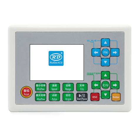
Figure: 3.2-1 Picture of Panel

RDLC320 Controller User Manual
10 /45
© 2016 Ruida Technology. All Rights Reserved.
Chapter 4 Description of IO Board Interface Signal
4.1 Interface of Main Power Source CN1
This control system employs single 24 power supply. For a certain
margin, it is suggested to select 24V/2A power. Besides, this system
is compatible with 36V power, that is to say, the 36V power of
Motion driver can directly be connected to this main power port of
this system, but generally it is not suggested to do so.
4.2 Panel Signal-Cable Interface HMI
HMI is a standard DB9 port, with the special cable shipped with the controller,
may connect the IO board and the panel.
4.3 General Output Port CN2
Definition of general output port (6Pin, 3.81mm space)
Pin
Symbols
Definitions
1
OGND
External power ground (output)
2
Out4
General output 4, with the function reserved.
3
Out3
General output 3, with the function reserved.
4
Out2
General output 2, and the signal port of operating status.
If this port is externally connected with the relay, the
relay coil is broken over when it works; no influence is
produced when it suspends working. When its work ends
or is stopped manually, the relay coil will be cut off.
5
Wind
General output 1. When the blower control is enabled,
this port will output the control signal of the blower,
otherwise it will output other special control signals.
When the blower is connected and its control enabled, the
blower switch can be set separately on each layer. If the
relay is connected externally, the relay coil will be broken
over when the blower is on; the relay coil will be cut off
when the blower is off.
6
O 24V
External power output (If the interface of main power
source is powered with 24V power supply, this pin should
be 24V; if it is powered with 36 V power supply, this pin
S.N
Symbols
Definitions
1
OGND
24V power ground (input)
2
+24V
24V power positive (input)
3
NC
NC
4
NC
NC
Caution

RDLC320 Controller User Manual
11 /45
© 2016 Ruida Technology. All Rights Reserved.
should be 36V.)
All outputs are isolated through the optocoupler, and 500mA current
for each, OC gate output, each can directly drive the 6V/24V relay.
4.4 3-axle Spacing and Special Input Interface CN3/CN4
Z-axle spacing and special input interface CN3 (6Pin, 3.81mm space)
No.
Symbols
Definitions
1
OGND
External power ground (output)
2
DrProc
Input from protective port. If the machine needs to be
protected in the special state (such as door open
protection), the protective signal can be inputted from
this pin. This pin can be enabled and prohibited. This
signal is not inquired by the controller if this pin is
prohibited; if this pin is enabled, when the input is
high-leveled or this input port is suspended, the
machine will be protected, the work suspended and
the laser closed.
3
FootSW
Input port of foot switch. The connection method is:
when the pedal is stepped down, the low-level signal
will be inputted to this port; when the pedal is
released, the port will be disconnected or the
high-level signal can be inputted to this port; when
the stepped-down pedal is held for not less than 100
ms, if the machine lies idle, it can be started for work;
if the machine is in the working state, the work will
be suspended; of the machine is in the suspension, the
work will be restarted, that is to say, the function of
the pedal switch is the same as that of the
“Start/Pause” key. If the interval time to the first
stepping-down of the pedal should be less than 1.5
seconds when the pedal is stepped down once again,
the second stepping-down of the pedal will be
considered invalid by the controller.
4
LmtZ-
The spacing from axle Z- and Z to 0 coordinate
5
LmtZ+
The spacing from axle Z- and Z to max. coordinate
6
O 5V
External power source + 5V (output)
Prompt

RDLC320 Controller User Manual
12 /45
© 2016 Ruida Technology. All Rights Reserved.
X/Y-axle spacing interface CN4 (6Pin, 3.81mm space)
No.
Symbols
Definitions
1
OGND
External power ground (output)
2
LmtY-
The spacing from axle Y- and Y to 0 coordinate
3
LmtY+
The spacing from axle Y+ and Y to max. coordinate
4
LmtX-
The spacing from axle X- and X to 0 coordinate
5
LmtX+
The spacing from axle X+ and X to max. coordinate
6
O 5V
External power source + 5V (output)
The spacing polarity is optional, that is to say, when the motion axle reaches the
spacing position, it will trigger a low-level signal so as to make the corresponding
LED (under the cover) light; when the motion axle leaves the spacing position, it will
trigger a high-level signal or disconnect the spacing signal so as to make the spacing
indicator go out, but when it leaves the spacing, the corresponding indicator will light
and the spacing polarity become positive. The mistaken setting of spacing polarity
will result that the spacing can’t be detected when the system is reset so as to lead to
the collision of axles.
4.5 X/Y/Z-axle Motion Drive Interface
The interfaces of the above three motion axles are the same (6Pin, 3.81mm space).
The Axle-X interface is exampled.
Pin
Symbols
Definitions
1
GND
Kernel power ground (output, only used for common
cathode connection of driver)
2
xDir+
Differential plus end of directional signal
3
xDir-
Differential minus end of directional signal
4
xPulse-
Differential minus end of pulse signal (when the common
anode connection is used and the pulse rising edge valid,
input will start from this pin.)
5
xPulse+
Differential plus end of pulse signal (when the common
anode connection is used and the pulse falling edge valid,
input will start from this pin.)
6
+5V
Kernel 5V power positive (output, only used for common
anode connection of driver)
The polarity of directional signal for driver pulse signal can be set. Where a
certain axle is reset, it will move to the opposite direction of machine origin, which
means the polarity of directional signal for this axle is not correct. In such a case, the
connection between this axle and the motor driver can be broken first (otherwise the
controller cannot be detected to the spacing so as to lead to the collision of this axle),

RDLC320 Controller User Manual
13 /45
© 2016 Ruida Technology. All Rights Reserved.
and then such a polarity can be corrected after this axle is reset completely. Upon the
correction, the reset key can be pressed against to reset the controller.
4.6 Laser Power Control Interface CN6/CN7
This control system has two independent and adjustable digital/analog laser
power control interfaces. Signals of the two interfaces are similar and the first digital
interface (CN6) is hereby exampled (6Pin, 3.81mm space):
Pin
Symbols
Definitions
1
LGND
Laser power 5V ground (output)
2
L-On1-
Laser-enabled control interface
1. When the laser is the RF laser, this pin will not be used;
2. When the laser is a glass tube, if the used laser is
outputted in the low-level form, this pin will be
connected with the laser power enable end and used to
control the ON/Off of laser.
3
L-On1+
Laser-enabled control interface
1. When the laser is the RF laser, this pin will not be used;
2. When the laser is a glass tube, if the used laser is
outputted in the high-level form, this pin will be
connected with the laser power enable end and used to
control the ON/Off of laser.
4
LPWM1+
Power control interface of laser/laser tube
1. When the laser is the RF laser, this pin will not be used;
2. When the laser is a glass tube and the laser power
PWM end is high-leveled, this pin will be connected with
the laser power PWM end and used to control the power
of the laser.
5
LPWM1-
Power control interface of laser/laser tube
1. When the laser is the RF laser, this pin will be
connected with the laser RF-PWM end;
2. When the laser is a glass tube and the laser power
PWM end is low-leveled, this pin will be connected with
the laser power PWM end and used to control the power
of the laser.
6
L-AN1
Analog voltage 1 and connected with the power control
end of the first analog laser power source
Please make corrective choice of laser type. After the option for
laser type is modified, the controller should be reset so that the
modification can be effected after resetting.
Prompt

RDLC320 Controller User Manual
14 /45
© 2016 Ruida Technology. All Rights Reserved.
4.7 Water Protect Input Interface CN5
Water protect input interface CN5 (5Pin, 3.81mm space):
Pin
Symbols
Definitions
1
LGND
Laser power 5V ground (output)
2
WP1
The input port of water protector for the first laser power
source. When the water protector 1 is enabled, the
controller will detect the input port of water protector 1. If
this port is of low level, it will be deemed normal; if this
port is of high level, the controller will forcibly close the
laser to suspend the work in progress and the system will
warn. If the water protector 1 is not enabled, the controller
will not detect the input port of water protector 1 and the
user not connect the water protector 1.
3
WP2
The input port of water protector for the second laser
power source. When the water protector 2 is enabled, the
controller will detect the input port of water protector 2. If
this port is of low level, it will be deemed normal; if this
port is of high level, the controller will forcibly close the
laser to suspend the work in progress and the system will
warn. If the water protector 2 is not enabled, the controller
will not detect the input port of water protector 2 and the
user not connect the water protector 2.
4
L-IN3
General input with the function reserved.
5
L5V
Laser power 5V positive (output)

RDLC320 Controller User Manual
15 /45
© 2016 Ruida Technology. All Rights Reserved.
Chapter 5 Examples of Laser Power Interface
5.1 Digital Laser Power Supply of Glass Tube
5.2 Analog Laser Power Supply of Glass Tube

RDLC320 Controller User Manual
16 /45
© 2016 Ruida Technology. All Rights Reserved.
5.3 RF CO2 Laser

RDLC320 Controller User Manual
17 /45
© 2016 Ruida Technology. All Rights Reserved.
Chapter 6 Examples of Driver Interface for Step-servo Motor
6.1 Overview
The input signal end of step-servo motor driver employs the light-coupled
isolation technology. For the step impulse signal, some isolate the diode side from off
to conduction (the valid falling edge of pulse signal input from the diode negative end)
and some do so from conduction to cutoff (e.g. the valid rising edge of pulse signal
input from the diode negative end). When it is indicated whether the pulse signal of
motor driver is the valid rising edge or the valid falling edge, it will be subject to the
pulse signal inputted from the minus end of side OC diode.
Some input signals of motor driver are independent and some are internally of
common anode, so some have 4 external leading-out wires and some 3 wires (only the
pulse and directional signals are counted) as shown in Figure 10 and 11. Meanwhile,
the input signal can generally be compatible with different voltage classes. If it is
higher than the 5V signal, it is necessary to connect the current-limiting resistance
externally. The interface signals of motor driver for RD controller are the 5V signals
that should directly be abutted with the corresponding terminals to the driver.
The interface pulse end of each motor driver for RD controller can provide such
two signals as the rising-edge walk and falling-edge travel. The improper use of the
pulse-end signal may give rise to the lost steps, even back-run and finally dislocation
of processed figure when the motor steers. In addition, this controller provide two
directional signals not restrict in requirements. Either signal can be connected with the
directional signal end of driver in the common-anode mode. Both directional signal
ends can also be connected with the driver in the differential mode. In such a case,
plus and minus can be exchanged at random. The result of exchange is that the
rotating direction of motor is different from the actually desired direction. At this time
the polarity of directional signal for the motor can be modified on the PC software. In
this section is exampled the driver of step-servo motor popular in the market. In
addition to that the correct wiring scheme of this controller and motor driver is
provided, it is recommended to use the common-anode connection in all wiring
schemes.
Figure: 6.1-1 Four Inputs, Independent
Input Signal of Driver
Figure: 6.1-2 Three Inputs,
Common-anode Input Signal of Driver

RDLC320 Controller User Manual
18 /45
© 2016 Ruida Technology. All Rights Reserved.
6.2 Valid Rising Edge for Pulse Signal
The driver of the step-servo motor produced by Leadshine Technology Co., Ltd.
is on the valid rising edge. Some of its products can support the mode of valid
rising/falling edge. When these products are delivered out of the factory, they are all
set at the valid rising edge; if the user changes the ex-factory setting into the valid
pulse falling edge, Section 6.3 can be referred to for the wiring method. For the
typical models such as M860 and 3MD560, Figure 6.2-1 and 6.2-2 show the wiring
scheme of RD controller and Leadshine driver.
6.3 Valid Falling Edge for Pulse Signal
The driver pulse ends of drivers for step-servo motors presently produced by most
of manufacturers are valid falling edge. The typical companies include BERGER
LAHR, Beijing HollySyn Motor Technology Co., Ltd., Shenzhen YAKO Automation
Technology Co., Ltd., Shenzhen Baishan Mechatronics Co., Ltd., Beijing
Jektechnology Co., Ltd. and the like. The input signals for some motor drivers are
independent and some of common anode.
(1). The drivers with independent input signals include D921 and WD3-00X from
Figure: 6.2-1 Four Inputs, Valid Rising Edge and Common Anode Connection
Figure: 6.2-2 Four Inputs, Valid Rising Edge and Differential Connection

RDLC320 Controller User Manual
19 /45
© 2016 Ruida Technology. All Rights Reserved.
BERGER LAHR, YKA3722MA from Shenzhen YAKO Automation Technology Co.,
Ltd., JK-2HB402M from Beijing Jektechnology Co., Ltd., Q2HB44MC(D) and
Q3HB64MA from Shenzhen Baishan Mechatronics Co., Ltd.
(2). The drivers with common-anode input signals, such as YKA2304ME from
Shenzhen YAKO Automation Technology Co., Ltd., Q2HB34MB and Q2HB44MA(B)
from Shenzhen Baishan Mechatronics Co., Ltd.
Figure: 6.3-3 Three Inputs, Valid Falling Edge and Common Anode Connection
Figure: 6.3-1 Four Inputs, Valid Falling Edge and Common Anode Connection
Figure: 6.3-2 Four Inputs, Valid Falling Edge and Differential Connection

RDLC320 Controller User Manual
20 /45
© 2016 Ruida Technology. All Rights Reserved.
Chapter 7 Examples of IO-port Wiring
7.1 Input Port
The input connection at X/Y minus spacing is exampled.
Figure: 7.1-1 Example of Input-port Connection
Table of contents
Other Ruida Technology Controllers manuals

Ruida Technology
Ruida Technology BWK301R User manual

Ruida Technology
Ruida Technology LFS-PM-T43 User manual

Ruida Technology
Ruida Technology RDC6332G User manual

Ruida Technology
Ruida Technology RDC6442U User manual

Ruida Technology
Ruida Technology LFS-ANM-T43-V2 User manual

Ruida Technology
Ruida Technology RDV3040-PCI User manual

Ruida Technology
Ruida Technology LFS-ANM-T43 User manual