HangZhou RuiDeng Technologies Co., Ltd
- 5 -
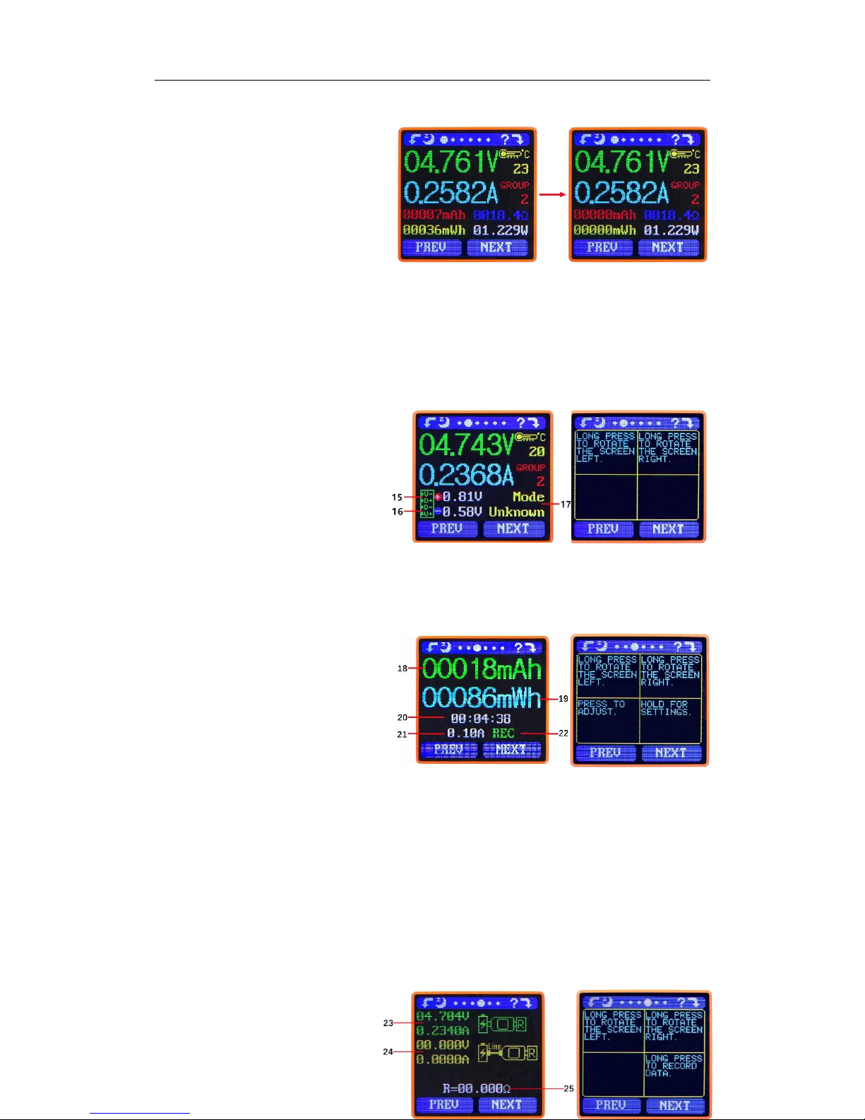
differential voltage method to measure the resistance of a data connection cable
23:USB Tester directly connected to the power supply with Voltage and Current values displayed
24:USB Tester connected via a data connection cable with Voltage and Current values displayed.
25:R: Data Connection Cable resistance.
Measurement procedure:
First, connect the USB Tester directly to the power supply and adjust the appropriate load
current (recommended value 1A) . Press and hold the ‘NEXT’ button to begin recording data. The
indicator prompt will stop flashing .
Second, unplug the USB Tester and then reconnect it to the power supply via the Micro
USB/Type-C IN data connection cable and adjust the load current to the same value as in the first
step. Press and hold the ‘NEXT’ button to begin recording data. The indicator prompt stops
flashing and the Data Connection Cable resistance measurement test is completed and the value
displayed.
Note: If during the second step the screen turns black, this indicates that the voltage difference is too high
and the tester will enter the 4V power-down state. The load current needs be reduced. Then re-start the
measurement from the first step. After the Data Connection Cable resistance test is completed, the Tester needs
to be powered off and then on again to resume measurement.
Press the ‘NEXT’ button to switch to the Measurement Graphing Interface.
Interface 5: Measurement Graphing Interface
This interface displays the voltage
measurement over time in the 4-24V
range and will automatically adjust the
displayed range in real time to account
for voltage fluctuations. And the current
measurement over time in the 0-5.000A
range and will automatically adjust the
display range in real time to account for current fluctuations.
Press and hold “NEXT” to switch to D+D- graphing, as picture
This interface displays the D+ /D-
voltage measurement over time in the
0-3.3V range and will automatically
adjust the displayed range in real time to
account for D+/D- voltage fluctuations.
Press the ‘NEXT’ button to switch to
the system parameter setting interface.
Interface 6: System Parameter Setting Interface
26:Auto screen off time
27:Screen brightness
28:Temperature display C /F
29:Theme background color
30:Theme foreground color
Press and hold the "Next" button