Ryobi BS1001SV Quick setup guide

RYOBI 10 in. (254 mm)
BAND SAW
MODEL NO. BS1001SV
REPAIR SHEET

2
RYOBI 10 in. (254 mm) BAND SAW – MODEL NUMBER BS1001SV
101
100
73
72
106
105
104
107
43
42
41
39 38
37
40
69
70
49
82 81
78
79
23
22
21 99
53
53
74
75
51
22
74
75
17
8
76
11
62
93
12
12
14
71 25
110
24 107
13
9
10
16
15 7
1115
5
56
1920
63
18 64
65
108
26 27 28
29
30 31 57
58 59
62
68
48102 111
56
68
67
55
66
103 54
112
113
109
34
35
36
31
30
29
28
86
85
84
98
98
96 80
83
50
9091
8988 87
62
61
60
77
95
94
97
92
2
3
3
4
4
44
33 45 46
47
32
6
52
79
114
FIGURE A
SEE NOTE
NOTE: The assembly shown represents an important part of the double insulated system. To avoid the possibility of alteration or damage to the
system, service should be performed by your nearest Ryobi Authorized Service Center. For the service center nearest you call 1-800-525-2579.

3
RYOBI 10 in. (254 mm) BAND SAW – MODEL NUMBER BS1001SV
The model number will be found on a plate attached to the motor housing. Always mention the model number in all correspondence regarding your BAND
SAW or when ordering repair parts.
PARTS LIST - FIGURE A
Key Part
No. Number Description Qty.
Key Part
No. Number Description Qty.
1 225308-000 FRAME ....................................................... 1
2 240065-000 BASE .......................................................... 1
3 020314-015 * HEX SCREW (M8 X 20 mm) ........................ 4
4 021204-001 WASHER .................................................... 4
5 303649-000 WHEEL LOCK KNOB ................................. 1
6 021118-002 WASHER .................................................... 1
7 060124-000 DRIVE CAM ................................................ 1
8 020804-012 * FLAT SCREW (M4 X 22 mm) ....................... 1
9 029185-001 COMPRESSION SPRING ............................ 1
10 270747-000 SLIDE ......................................................... 1
11 270677-000 SLIDE PLATE .............................................. 1
12 020102-025 * PAN SCREW (M6 X 12 mm) ........................ 8
13 900982-000 UPPER WHEEL BASE ASSEMBLY .............. 1
14 270218-000 LOCK PLATE .............................................. 1
15 029194-001 COMPRESSION SPRING ............................ 1
16 021120-003 WASHER .................................................... 1
17 303650-000 WHEEL ADJUSTMENT KNOB ..................... 1
18 303651-001 ADJUSTMENT KNOB ................................. 1
19 021101-008 WASHER .................................................... 1
20 022111-002 HEX NUT .................................................... 1
21 901071-000 UPPER WHEEL ASSEMBLY ........................ 1
22 021504-009 INSULATION WASHER ................................ 2
23 023102-001 “C” RING .................................................... 1
24 901072-000 BLADE GUIDE ASSEMBLY ......................... 1
25 028989-001 CARRIAGE BOLT ........................................ 1
26 303734-000 DRIVE KNOB .............................................. 1
27 029192-001 COMPRESSION SPRING ............................ 1
28 021101-013 WASHER .................................................... 2
29 303653-000 LOCK KNOB .............................................. 2
30 022301-001 NYLON NUT ............................................... 2
WARNING: Improper repair of a double insulated tool can result in damage to the double insulation system possibly causing electrical shock or
electrocution. Any repairs requiring disassembly of your tool requires safety testing and should only be performed by a Ryobi Authorized Service
Center. For the service center nearest you call 1-800-525-2579.
* Standard Hardware Item – May Be Purchased Locally
31 303695-000 LOCK KNOB END PLATE ........................... 2
32 990038-000 MOTOR ASSEMBLY ................................... 1
33 041007-000 GEAR BELT ................................................ 1
34 6616922 * SCREW (M8 × 35 mm) ................................ 3
35 021204-001 S WASHER ................................................. 3
36 021120-017 WASHER .................................................... 3
37 901073-000 LOWER WHEEL SHAFT ASSEMBLY ........... 1
38 270748-000 BEARING COVER ....................................... 1
39 020106-035 PAN SCREW (CROSS) ................................ 2
40 027201-002 KEY ............................................................ 1
41 901074-000 LOWER WHEEL ASSEMBLY....................... 1
42 020300-011 * SCREW (M8 X 14 mm) ................................ 1
43 330095-000 FAN END CAP ............................................ 1
44 303735-000 DRIVE GEAR .............................................. 1
45 021125-009 WASHER .................................................... 1
46 020601-007 * SCREW (M5 × 12 mm) ................................ 1
47 303736-000 DRIVE GEAR COVER ................................. 1
48 020103-002 * PAN SCREW (M4 × 12 mm) ........................ 2
49 901075-000 SUPPORT GUIDE ASSEMBLY .................... 1
50 020504-007 * SCREW (M6 X 8 mm) .................................. 1
51 984406001 SWITCH (KEDU HY 18-13) .......................... 1
52 270689-000 SWITCH PLATE ........................................... 1
53 020103-033 * PAN SCREW (M4 × 10 mm) ........................ 4
54 080406-003 POWER CORD (18 AWG X 1945L) .............. 1
55 303737-000 SWITCH COVER ......................................... 1
56 330082-000 GROMMET ................................................. 3
57 270749-000 CORD LOCK PLATE ................................... 1
58 020106-035 * PAN SCREW (CROSS) (M5 X 8 mm)............ 3
59 913001-000 STRAIN RELIEF ........................................... 2

4
RYOBI 10 in. (254 mm) BAND SAW – MODEL NUMBER BS1001SV
The model number will be found on a plate attached to the motor housing. Always mention the model number in all correspondence regarding your BAND
SAW or when ordering repair parts.
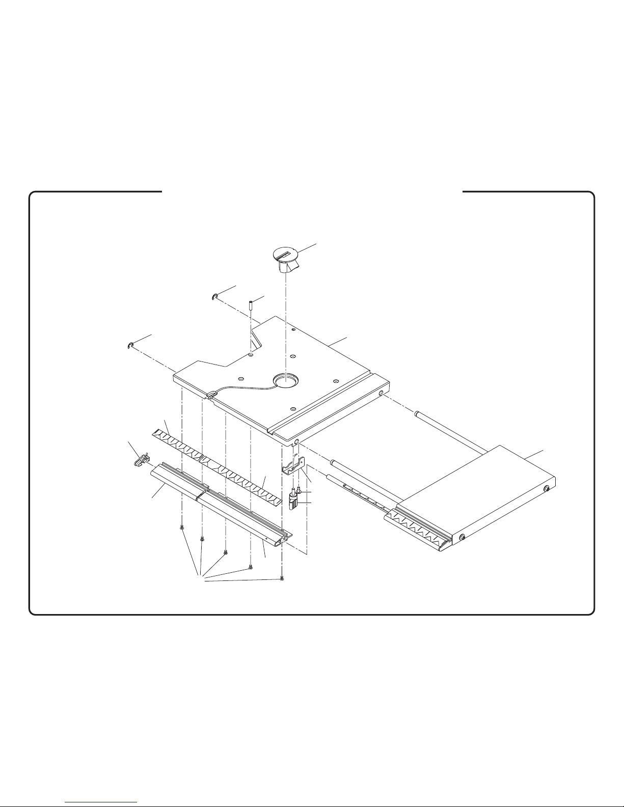
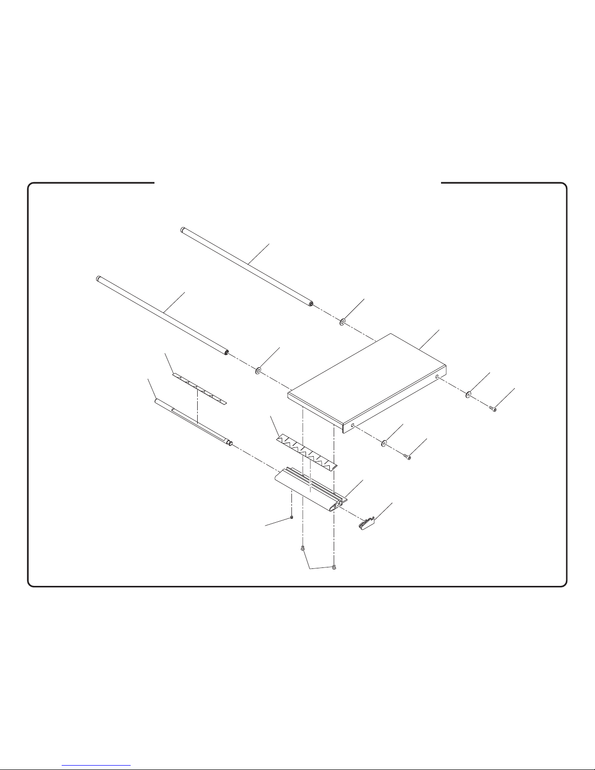
PARTS LIST - FIGURE A CONTINUED
Key Part
No. Number Description Qty.
Key Part
No. Number Description Qty.
WARNING: Improper repair of a double insulated tool can result in damage to the double insulation system possibly causing electrical shock or
electrocution. Any repairs requiring disassembly of your tool requires safety testing and should only be performed by a Ryobi Authorized Service
Center. For the service center nearest you call 1-800-525-2579.
* Standard Hardware Item – May Be Purchased Locally
60 021306-002 WASHER .................................................... 2
61 021201-003 S WASHER ................................................. 2
62 020103-031 * PAN SCREW (M4 × 8 mm) .......................... 6
63 372013-000 TRANSFORMER ......................................... 1
64 303762-000 TRANSFORMER LOCK ............................... 1
65 364001-001 TERMINAL .................................................. 2
66 080506-001 SWITCH WIRE (18 AWG X 100L, BLACK) ... 1
67 080506-000 SWITCH WIRE (18 AWG X 100L, WHITE) .... 1
68 020106-036 * PAN SCREW (M5 × 12 mm) ........................ 3
69 330083-000 GASKET (970 mm) ...................................... 1
70 330083-001 GASKET (80 mm) ........................................ 1
71 914024-000 SPONGE ..................................................... 1
72 351009-002 BLADE (1/4 in.) ........................................... 1
351009-003 BLADE (3/8 in.) ........................................... 1
73 901076-000 COVER ASSEMBLY .................................... 1
74 270680-000 HINGE ........................................................ 2
75 024201-000 RIVET ......................................................... 8
76 330096-000 LOCK WIRE ROD ....................................... 1
77 290295-000 UPPER LOCK SHAFT ................................. 1
78 290296-000 LOWER LOCK SHAFT ................................ 1
79 022111-007 * HEX NUT (M6) ............................................. 2
80 028977-000 SCREW ...................................................... 1
81 021200-001 WASHER .................................................... 1
82 022306-000 NYLON NUT ............................................... 1
83 901149-000 TABLE SUPPORT BRACKET ASSEMBLY ... 1
84 021118-001 WASHER .................................................... 1
85 303660-000 MICRO-ADJUSTING GEAR ......................... 1
86 029138-000 COMPRESSION SPRING ............................ 1
87 028976-000 SCREW ...................................................... 1
88 021403-007 WAVE WASHER .......................................... 1
89 021103-010 WASHER .................................................... 1
90 303738-000 BEVEL INDICATOR ..................................... 1
91 020716-000 * PAN SCREW ASSEMBLY (M5 X 8 mm) ....... 1
92 901070-000 TABLE ASSEMBLY ..................................... 1
93 303006-000 CORD CLAMP ............................................ 1
94 022603-000 * WING NUT (M6) .......................................... 1
95 021101-011 WASHER .................................................... 1
96 028967-000 * BOLT (M6 X 19 mm) ................................... 1
97 040005-003 WRENCH (3 mm) ........................................ 1
98 020808-007 * SCREW (M6 X 21 mm) ................................ 4
99 984406003 SWITCH KEY .............................................. 1
100 863209-000 3D LOGO ................................................... 1
101 863210-003 WARNING LABEL ....................................... 1
102 871059-000 RATING LABEL ........................................... 1
103 863209-002 BLADE TRACKING AND ADJUSTING LABEL1
104 863210-004 BLADE CHART (FRENCH) ........................... 1
105 863210-005 BLADE CHART (ENGLISH) .......................... 1
106 863210-006 BLADE CHART (SPANISH) ........................... 1
107 863209-003 KEEP HANDS AWAY WARNING LABEL ...... 2
108 863209-004 LABEL FOR WINDOW ................................ 1
109 863209-005 TRACKING LABEL ...................................... 1
110 870039-000 CUTTING DEPTH SCALE ............................ 1
111 870037-001 BEVEL SCALE ............................................ 1
112 916141-003 POWER SUPPLY CORD WARNING LABEL . 1
113 915008-000 NYLON TIE ................................................. 1
114 901119-000 DUST BAG ASSEMBLY............................... 1
115 021419001 WAVY WASHER .......................................... 1
983000-269 OPERATOR'S MANUAL
983000-269R REPAIR SHEET (REV:00)
11-09-04

5
RYOBI 10 in. (254 mm) BAND SAW – MODEL NUMBER BS1001SV
3
2
3
2
4
9
10
17
6
5
6
11
6
13
13
14
6
12
20
618
6
6
19
20
16
8
6
4
8
7
21
1
15
FIGURE B

6
RYOBI 10 in. (254 mm) BAND SAW – MODEL NUMBER BS1001SV
The model number will be found on a plate attached to the motor housing. Always mention the model number in all correspondence regarding your BAND
SAW or when ordering repair parts.
PARTS LIST - FIGURE B
Key Part
No. Number Description Qty.
WARNING: Improper repair of a double insulated tool can result in damage to the double insulation system possibly causing electrical shock or
electrocution. Any repairs requiring disassembly of your tool requires safety testing and should only be performed by a Ryobi Authorized Service
Center. For the service center nearest you call 1-800-525-2579.
* Standard Hardware Item – May Be Purchased Locally
1 303739-000 COVER .............................................................................................. 1
2 303656-000 DOOR LOCK KNOB .......................................................................... 2
3 029187-001 COMPRESSION SPRING ................................................................... 2
4 303763-000 SUPPORT COVER ............................................................................. 2
5 303740-000 TRACKING WINDOW ......................................................................... 1
6 020132-001 * SELF-TAPPING SCREW (M4 X 10 mm) .............................................. 1
7 303741-000 STRIPPER .......................................................................................... 1
8 303742-000 BRUSH .............................................................................................. 3
9 901120-000 LED LAMP ......................................................................................... 1
10 303743-000 LED FIXED SUPPORT ........................................................................ 1
11 303744-000 SWTICH PROTECT COVER ............................................................... 1
12 303745-000 PUSH BUTTON .................................................................................. 1
13 020109-007 * SCREW (M3 X 0.5 mm) ...................................................................... 2
14 020200-001 * SELF-TAPPING SCREW (M4 X 20 mm) .............................................. 1
15 303746-000 LED BOX ........................................................................................... 1
16 303747-000 WIRE PROTECT PLATE A .................................................................. 1
17 303748-000 WIRE PROTECT PLATE B .................................................................. 1
18 303006-000 CORD CLAMP ................................................................................... 1
19 330083-002 GASKET (73 mm) ............................................................................... 1
20 330083-003 GASKET (53 mm) ............................................................................... 3
21 330083-004 GASKET (28 mm) ............................................................................... 2

7
RYOBI 10 in. (254 mm) BAND SAW – MODEL NUMBER BS1001SV
2
12
3
1
8
10
11
9
7
5
6
14
13
12
4
FIGURE C

8
RYOBI 10 in. (254 mm) BAND SAW – MODEL NUMBER BS1001SV
The model number will be found on a plate attached to the motor housing. Always mention the model number in all correspondence regarding your BAND
SAW or when ordering repair parts.
PARTS LIST - FIGURE C
Key Part
No. Number Description Qty.
WARNING: Improper repair of a double insulated tool can result in damage to the double insulation system possibly causing electrical shock or
electrocution. Any repairs requiring disassembly of your tool requires safety testing and should only be performed by a Ryobi Authorized Service
Center. For the service center nearest you call 1-800-525-2579.
* Standard Hardware Item – May Be Purchased Locally
1 225307-000 TABLE ............................................................................................... 1
2 303729-000 TABLE INSERT .................................................................................. 1
3 020504-023 * SCREW SET (M6 X 22 mm) ................................................................ 1
4 203041-000 RIGHT RAIL ....................................................................................... 1
5 203041-001 LEFT RAIL .......................................................................................... 1
6 303730-000 LEFT CAP RAIL .................................................................................. 1
7 020716-007 * SCREW (M5 X 10 mm) ....................................................................... 5
8 901069-000 TABLE EXTENSION ASSEMBLY ........................................................ 1
9 303764-000 KNOB ................................................................................................ 1
10 270785-000 CLAMP BRACKET ............................................................................. 1
11 030000-007 SPECIAL SCREW ............................................................................... 1
12 023204-001 E-RING (E8) ....................................................................................... 2
13 870039-001 RIGHT SCALE .................................................................................... 1
14 870039-004 LEFT SCALE ...................................................................................... 1

9
RYOBI 10 in. (254 mm) BAND SAW – MODEL NUMBER BS1001SV
2
3
1
4
5
5
4
2
3
12
9
11
10
8
7
6
FIGURE D

10
RYOBI 10 in. (254 mm) BAND SAW – MODEL NUMBER BS1001SV
The model number will be found on a plate attached to the motor housing. Always mention the model number in all correspondence regarding your BAND
SAW or when ordering repair parts.
PARTS LIST - FIGURE D
Key Part
No. Number Description Qty.
WARNING: Improper repair of a double insulated tool can result in damage to the double insulation system possibly causing electrical shock or
electrocution. Any repairs requiring disassembly of your tool requires safety testing and should only be performed by a Ryobi Authorized Service
Center. For the service center nearest you call 1-800-525-2579.
* Standard Hardware Item – May Be Purchased Locally
1 270746-000 EXTENSION TABLE ........................................................................... 1
2 290292-000 SLIDE BAR ........................................................................................ 2
3 021120-003 WASHER ........................................................................................... 2
4 021125-011 WASHER ........................................................................................... 2
5 020601-007 * SCREW (M5 X 12 mm) ....................................................................... 2
6 203040-000 EXTENSION BAR ............................................................................... 1
7 303731-000 RIGHT END PLATE ............................................................................ 1
8 020716-007 * SCREW SET (M5 X 10 mm) ................................................................ 2
9 290294-000 EXTENSION RAIL ROD ...................................................................... 1
10 020502-003 * SELF-TAPPING SCREW (M5 X 5 mm) ................................................ 1
11 870039-002 EXTENSION BAR SCALE ................................................................... 1
12 870039-003 RAIL ROD SCALE .............................................................................. 1
901069-000 TABLE ASSEMBLY ............................................................................ 1

11
RYOBI 10 in. (254 mm) BAND SAW – MODEL NUMBER BS1001SV
FIGURE E
1
2
3
4
8
6
7
11
17
16
15
21
12
19
18
13
14
21
5
11
10
9
20

12
RYOBI 10 in. (254 mm) BAND SAW – MODEL NUMBER BS1001SV
The model number will be found on a plate attached to the motor housing. Always mention the model number in all correspondence regarding your BAND
SAW or when ordering repair parts.
PARTS LIST - FIGURE E
Key Part
No. Number Description Qty.
WARNING: Improper repair of a double insulated tool can result in damage to the double insulation system possibly causing electrical shock or
electrocution. Any repairs requiring disassembly of your tool requires safety testing and should only be performed by a Ryobi Authorized Service
Center. For the service center nearest you call 1-800-525-2579.
* Standard Hardware Item – May Be Purchased Locally
1 290274-001 CLAMP ROD ...................................................................................... 1
2 270777-000 REAR CLAMP .................................................................................... 1
3 029136-000 SPRING ............................................................................................. 1
4 303156-000 REAR SLIDING PAD ........................................................................... 1
5 225315-000 RIP FENCE HOUSING ........................................................................ 1
6 020624-000 * SCREW (M6 X 12 mm) ....................................................................... 2
7 021300-002 LOCK WASHER ................................................................................. 2
8 203042-000 FENCE ............................................................................................... 1
9 270776-000 BRACKET FENCE CAM ..................................................................... 1
10 303766-000 PROTECT PAD .................................................................................. 1
11 020726-003 * SCREW (M4 X 8 mm) ......................................................................... 2
12 060126-000 CAM .................................................................................................. 1
13 290305-000 CAM PIN ............................................................................................ 1
14 290306-000 LEVER PIN ......................................................................................... 1
15 022119-001 REAR CLAMP SCREW ....................................................................... 1
16 029135-000 SPRING ............................................................................................. 1
17 303749-000 INDICATOR ........................................................................................ 1
18 901141-000 HANDLE ............................................................................................ 1
19 022108-000 NUT ................................................................................................... 1
20 303751-000 FENCE COVER .................................................................................. 1
21 303752-000 SLIDING PAD ..................................................................................... 2
901142-000 RIP FENCE ASSEMBLY ..................................................................... 1

13
RYOBI 10 in. (254 mm) BAND SAW – MODEL NUMBER BS1001SV
FIGURE F
3
1
6
4
5
5
2
7
8
9
5

14
RYOBI 10 in. (254 mm) BAND SAW – MODEL NUMBER BS1001SV
The model number will be found on a plate attached to the motor housing. Always mention the model number in all correspondence regarding your BAND
SAW or when ordering repair parts.
PARTS LIST - FIGURE F
Key Part
No. Number Description Qty.
WARNING: Improper repair of a double insulated tool can result in damage to the double insulation system possibly causing electrical shock or
electrocution. Any repairs requiring disassembly of your tool requires safety testing and should only be performed by a Ryobi Authorized Service
Center. For the service center nearest you call 1-800-525-2579.
* Standard Hardware Item – May Be Purchased Locally
1 225314-000 LOWER WHEEL ................................................................................. 1
2 060125-000 SHAFT SHEATH ................................................................................. 1
3 303753-000 FAN ................................................................................................... 1
4 916141-002 PVC STICKER .................................................................................... 1
5 020132-000 * SCREW (M4 X 14 mm) ....................................................................... 6
6 330077-000 WHEEL TIRE ...................................................................................... 1
7 290298-000 LOWER WHEEL SHAFT ..................................................................... 1
8 050051-100 * BEARING (6002Z) .............................................................................. 2
9 023108-001 * C-RING (S-15) .................................................................................... 1
901073-000 SHAFT ASSEMBLY (INCLUDES KEY NOS. 7-9)

15
RYOBI 10 in. (254 mm) BAND SAW – MODEL NUMBER BS1001SV
FIGURE G
1
2
3

16
RYOBI 10 in. (254 mm) BAND SAW – MODEL NUMBER BS1001SV
The model number will be found on a plate attached to the motor housing. Always mention the model number in all correspondence regarding your BAND
SAW or when ordering repair parts.
PARTS LIST - FIGURE G
Key Part
No. Number Description Qty.
WARNING: Improper repair of a double insulated tool can result in damage to the double insulation system possibly causing electrical shock or
electrocution. Any repairs requiring disassembly of your tool requires safety testing and should only be performed by a Ryobi Authorized Service
Center. For the service center nearest you call 1-800-525-2579.
* Standard Hardware Item – May Be Purchased Locally
1 225310-000 UPPER WHEEL .................................................................................. 1
2 050013-000 BEARING (6000Z) .............................................................................. 2
3 330077-000 TIRE WHEEL ...................................................................................... 1

17
RYOBI 10 in. (254 mm) BAND SAW – MODEL NUMBER BS1001SV
4
1
3
2
6
5
7
8
9
FIGURE H

18
RYOBI 10 in. (254 mm) BAND SAW – MODEL NUMBER BS1001SV
PARTS LIST FOR FIGURE H
Key Part
No. Number Description Qty.
900988-000 MITER GAUGE ASSEMBLY .................................. 1
1 224074-000 MITER GAUGE ..................................................... 1
2 026205-001 PIN ....................................................................... 1
3 203037-000 BAR ..................................................................... 1
4 900990-000 MITER GAUGE KNOB .......................................... 1
5 303663-000 INDICATOR .......................................................... 1
6 020103-031 * SEMS SCREW (M4 X 8 mm) ................................. 1
7 021101-039 WASHER .............................................................. 1
8 863209-006 LOGO PLATE ....................................................... 1
9 870037-002 MITER SCALE ...................................................... 1
The model number will be found on a plate attached to the motor housing. Always mention the model number in all correspondence regarding your BAND
SAW or when ordering repair parts.
WARNING: Improper repair of a double insulated tool can result in damage to the double insulation system possibly causing electrical shock or
electrocution. Any repairs requiring disassembly of your tool requires safety testing and should only be performed by a Ryobi Authorized Service
Center. For the service center nearest you call 1-800-525-2579.
* Standard Hardware Item – May Be Purchased Locally

19
RYOBI 10 in. (254 mm) BAND SAW – MODEL NUMBER BS1001SV
FIGURE I
1
2
3
45

20
RYOBI 10 in. (254 mm) BAND SAW – MODEL NUMBER BS1001SV
PARTS LIST FOR FIGURE I
Key Part
No. Number Description Qty.
1 225311-100 UPPER SLIDE ...................................................... 1
2 901075-000 SUPPORT GUIDE ASSEMBLY .............................. 1
3 020504-007 * SET SCREW (M6 X 8 mm) .................................... 1
4 270750-000 BLADE GUARD .................................................... 1
5 020106-035 * SCREW (M5 X 8 mm) ........................................... 2
901072-000 BLADE GUIDE ASSEMBLY
(INCLUDES KEY NOS. 1-5) .................................. 1
The model number will be found on a plate attached to the motor housing. Always mention the model number in all correspondence regarding your BAND
SAW or when ordering repair parts.
WARNING: Improper repair of a double insulated tool can result in damage to the double insulation system possibly causing electrical shock or
electrocution. Any repairs requiring disassembly of your tool requires safety testing and should only be performed by a Ryobi Authorized Service
Center. For the service center nearest you call 1-800-525-2579.
* Standard Hardware Item – May Be Purchased Locally
Other manuals for BS1001SV
1
Table of contents
Other Ryobi Saw manuals

Ryobi
Ryobi EMS254L-LSG User manual

Ryobi
Ryobi CS120L User manual

Ryobi
Ryobi CSB142LZ User manual

Ryobi
Ryobi R18RS User manual

Ryobi
Ryobi ETMS-1426 User manual

Ryobi
Ryobi P511 User manual

Ryobi
Ryobi P531 User manual

Ryobi
Ryobi RTS721S User manual

Ryobi
Ryobi EMS2305SCL Operation manual

Ryobi
Ryobi CSB133L User manual
Popular Saw manuals by other brands

Black & Decker
Black & Decker BD 227 operating instructions

holzkraft
holzkraft HWSR 701 K Translation from the original instruction manual

Hitachi
Hitachi CM 75EBP Handling instructions

Jet
Jet JTS 600X-T operating instructions

Tool Shed
Tool Shed TSB10 instructions

Black & Decker
Black & Decker CS1500 operating instructions