Ryobi 705r User manual

FOR QUESTIONS, CALL 1-800-345-8746 in U.S. or
1-800-265-6778 in CANADA
www.ryobi.com
IMPORTANT MANUAL DO NOT THROW AWAY
7
0
5
r
T
r
i
m
m
e
r
P
l
u
s
®
OPERATOR’S MANUAL
2-Cycle Gas Trimmer
705r – 725r

THANK YOU
Thank you for buying this quality product. This
modern outdoor power tool will provide many
hours of useful service. You will find it to be a
great labor-saving device. This operator’s
manual provides you with easy-to-understand
operating instructions. Read the whole manual
and follow all the instructions to keep your new
outdoor power tool in top operating condition.
The other manual that came with your power
tool, the parts manual, contains all the
information that you need to order parts.
PRODUCT REFERENCES,
ILLUSTRATIONS AND
SPECIFICATIONS
All information, illustrations and specifications
in this manual are based on the latest product
information available at the time of printing. We
reserve the right to make changes at any time
without notice.
Copyright© 1998 Ryobi Outdoor Products, Inc.
All Rights Reserved.
Click-Link®and SpeedSpool®are registered
trademarks of Ryobi Outdoor Products.
Bump Head™is a trademark of Ryobi Outdoor
Products.
SERVICE INFORMATION
Service on this unit both within and after the
warranty period should be performed only by
an authorized and approved service dealer.
Dial:
1-800-345-8746 in the United States or
1-800-265-6778 in Canada
to obtain the listing of the authorized service
dealer nearest you.
DO NOT RETURN THE UNIT TO THE
RETAILER.
NOTE: PROOF OF PURCHASE WILL BE
REQUIRED FOR WARRANTY
SERVICE.
Make sure this manual is carefully read and
understood before starting or operating this
equipment.
THIS PRODUCT IS COVERED BY ONE OR
MORE OF THE US PATENTS LISTED BELOW:
5,076,149; 4,901,682; 4,779,405; 4,651,422;
4,505,040; 4,463,498; 4,369,742; 4,342,236;
4,223,441; 2,125,688; D-249,012; D-239,329;
OTHER PATENTS PENDING.
INTRODUCTION
2
TABLE OF CONTENTS
I. California Emission Regulations . . . . . . . . 3
II. Rules for Safe Operation . . . . . . . . . . . 4-8
A. Important Safty Information . . . . . . . .4-5
B. Safety and International Symbols . . .6-7
C. Know Your Unit . . . . . . . . . . . . . . . . . .8
III. Assembly Instructions . . . . . . . . . . . . 9-10
A. Installing and Adjusting D-Handle
(Model 705r) . . . . . . . . . . . . . . . . . . . . 9
B. Installing and Adjusting J-Handle
(Model 725r) . . . . . . . . . . . . . . . . . 9-10
C. Installing Cutting Attachment Shield . 10
IV. Oil and Fuel Information . . . . . . . . . . . . . 11
V. Starting/Stopping Instructions . . . . . . . . 12
VI. Operating Instructions . . . . . . . . . . . 13-15
A. Operating Click-Link System (725r) . . .13
B. Holding the Trimmer . . . . . . . . . . . . . .14
C. Adjusting Trimming Line Length . . . . .14
D. Tips for Best Trimming Results . . . . . .15
E. Decorative Trimming . . . . . . . . . . . . . .15
F. Edging - Model 725r Only . . . . . . . . . .15
VII. Maintenance and Repair Instructions .15-21
A. Maintenance Schedule . . . . . . . . . . . 15
B. Line Installation for the SpeedSpool . 16
C. Winding the Inner Reel with New Line 16
D. Installing a Prewound Reel . . . . . . . . . 17
E. Releasing the Inner Reel . . . . . . . . . . 17
F. Cleaning the SpeedSpool . . . . . . . 17-18
G. Air Filter/Muffler Cover Removal and
Installation . . . . . . . . . . . . . . . . . . . . .18
H. Air Filter Maintenance . . . . . . . . . . . . 19
I. Carburetor Adjustment . . . . . . . . . . . 20
J. Replacing the Spark Plug . . . . . . . . . 21
K. Accessories and replacement parts . . 21
VIII. Cleaning and Storage . . . . . . . . . . . . . . 22
IX. Transporting . . . . . . . . . . . . . . . . . . . . . .22
X. Troubleshooting Chart . . . . . . . . . . . . . . 23
XI. Specifications . . . . . . . . . . . . . . . . . . . . 24
XII. Warranty . . . . . . . . . . . . . . . . . . . . . .25-26
CONTENTS OF CARTON
This unit should consist of the following:
•Model 705r or Model 725r Trimmer
D-Handle and Hardware (Model 705r)
J-Handle and Hardware (Model 725r)
String Guard and Hardware
•Bottle of 2-Cycle Oil
•Operator's Manual
•Parts Manual
•Product Registration Card
These items may be in the hardware bag or
assembled on your unit.

WARNING!
3
SPARK ARRESTOR
WARNING
CALIFORNIA EMISSION REGULATIONS
NOTE: For users on U.S. Forest Land and in the states of California, Maine, Oregon and Washington.
All U.S. Forest Land and the states of California (Public Resources Codes 4442 and 4443), Oregon and
Washington require, by law that certain internal combustion engines operated on forest brush and/or grass-
covered areas be equipped with a spark arrestor, maintained in effective working order, or the engine be
constructed, equipped and maintained for the prevention of fire. Check with your state or local authorities for
regulations pertaining to these requirements. Failure to follow these requirements could subject you to liability
or a fine. This unit is not factory equipped with a spark arrestor. If these items are required in your area,
ask your LOCAL SERVICE dealer to install the Optional Accessory Part #180030 Spark Arrestor Kit.
FOR QUESTIONS, CALL 1-800-345-8746 IN U.S. OR 1-800-265-6778 in CANADA
California Proposition 65 Warning:
THE ENGINE EXHAUST FROM THIS
PRODUCT CONTAINS CHEMICALS
KNOWN TO THE STATE OF
CALIFORNIA TO CAUSE CANCER,
BIRTH DEFECTS OR OTHER
REPRODUCTIVE HARM.
This unit meets the 1995 to 1998 California emissions regulations for small off-road engines. These
units are identified by the label on the engine of your product. A typical identification label is shown.
To ensure that your unit continues to meet these regulations, refer to the following information and
instructions in this operator’s manual.
Read the Operator’s Manual(s) and follow all warnings and safety
instructions. Failure to do so can result in serious injury to the operator
and/or bystanders.

RULES FOR SAFE OPERATION
4
•Clear the area to be cut before each use.
Remove all such objects such as rocks,
broken glass, nails, wire, or string which can
be thrown or become entangled in the
cutting attachment. Clear the area of
children, bystanders, and pets. At a
minimum, keep all children, bystanders and
pets outside a 50 ft. (15m.) radius; there still
may be a risk to bystanders from thrown
objects. Bystanders should be encouraged
to wear eye protection. If you are
approached, stop the engine and cutting
attachment immediately.
•Squeeze the throttle control and check that it
returns automatically to the neutral position.
Make all adjustments or repairs before using
unit.
•This unit was not designed to be used as a
brushcutter. Do not attach or operate this
unit with any type of brushcutting blade or
brushcutting attachment.
SAFETY WARNINGS FOR GAS
TRIMMERS
WARNING: Gasoline is highly flammable, and its
vapors can explode if ignited. Take the following
precautions:
•Store fuel only in containers specifically
designed and approved for the storage of
such materials.
READ ALL INSTRUCTIONS
BEFORE OPERATING
•Read the instructions carefully. Be familiar
with the controls and proper use of the unit.
•Do not operate this unit when tired, ill, or
under the influence of alcohol, drugs, or
medication.
•Children and teens under the age of 15 must
not use the unit, except for teens guided by
an adult.
•Inspect the unit before use. Replace
damaged parts. Check for fuel leaks. Make
sure all fasteners are in place and secure.
Replace cutting attachment parts that are
cracked, chipped, or damaged in any way.
Make sure the cutting attachment is properly
installed and securely fastened. Be sure the
cutting attachment shield is properly
attached, and positioned as recommended.
Failure to so can result in personal injury to
the operator and bystanders, as well as
damage to the unit.
•Use only 0.080 in (2.03 mm) diameter
genuine Ryobi replacement line. Never use
metal-reinforced line, wire, or rope, etc..
These can break off and become a
dangerous projectile.
•Be aware of the risk of injury to the head,
hands and feet.
• IMPORTANT SAFETY INFORMATION •
DANGER: Failure to obey a safety
warning will result in serious injury
to yourself or to others. Always
follow the safety precautions to
reduce the risk of fire, electric
shock, and personal injury.
WARNING: Failure to obey a safety
warning can result in injury to
yourself and others. Always follow
the safety precautions to reduce the
risk of fire, electric shock, and
personal injury.
CAUTION: Failure to obey a safety
warning may result in property
damage or personal injury to
yourself or to others. Always follow
the safety precautions to reduce the
risk of fire, electric shock, and
personal injury.
The purpose of safety symbols is to attract your
attention to possible dangers. The safety
symbols, and their explanations, deserve your
careful attention and understanding. The safety
warnings do not by themselves eliminate any
danger. The instructions or warnings they give
are not substitutes for proper accident
prevention measures.
SYMBOL MEANING
SAFETY ALERT SYMBOL:
Indicates danger, warning, or
caution. Attention is required in
order to avoid serious personal
injury. May be used in conjunction
with other symbols or pictographs.
NOTE: Advises you of information or
instructions vital to the operation or
maintenance of the equipment.

RULES FOR SAFE OPERATION
5
•Always stop the engine and allow it to cool
before filling the fuel tank. Never remove the
cap of the fuel tank, or add fuel, when the
engine is hot. Never operate the unit without
the fuel cap securely in place. Loosen the
fuel tank cap slowly to relieve any pressure in
the tank.
•Mix and add fuel in a clean, well-ventilated
area outdoors where there are no sparks or
flames. Slowly remove the fuel cap only after
stopping engine. Do not smoke while fueling
or mixing fuel. Wipe up any spilled fuel from
the unit immediately.
•Avoid creating a source of ignition for spilled
fuel. Do not start the engine until fuel vapors
dissipate.
•Move the unit at least 30 ft. (9.1 m) from the
fueling source and site before starting the
engine. Do not smoke, keep sparks and
open flames from the area while adding fuel
or operating the unit.
WHILE OPERATING
•Never start or run the unit inside a closed
room or building. Breathing exhaust fumes
can kill. Operate this unit only in a well
ventilated area outdoors.
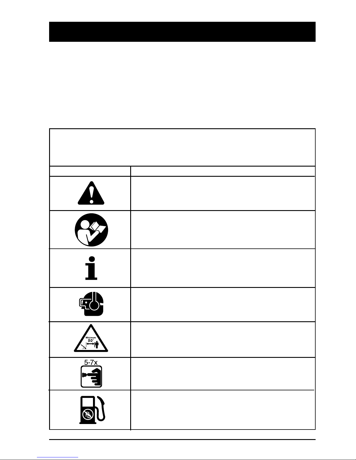
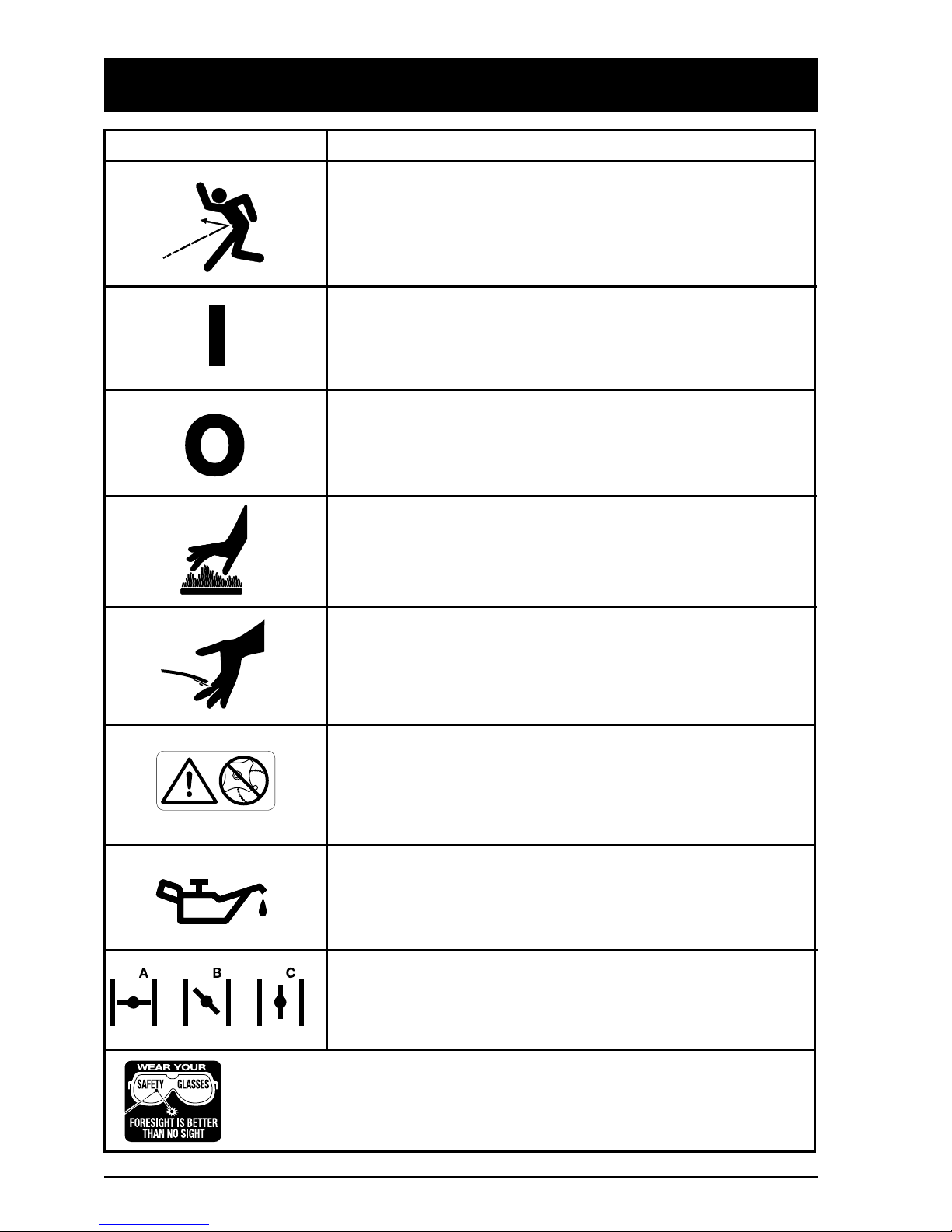
•Wear safety glasses or goggles that are
marked as meeting ANSI Z87.1-1989
standards, and ear/hearing protection when
operating this unit. Wear a face or dust mask
if the operation is dusty. Long sleeve shirts
are recommended.
•Wear heavy, long pants, boots and gloves.
Do not wear loose clothing, jewelry, short
pants, sandals or go barefoot. Secure hair
above shoulder level.
•The cutting attachment shield must always
be in place while operating the unit. Do not
operate unit without both trimming lines
extended, and the proper line installed. Do
not extend the trimming line beyond the
length of the shield.
•This unit has a clutch. The cutting attachment
remains stationary when the engine is idling.
If it does not, have the unit adjusted by an
authorized service technician.
•Adjust the handle to your size to provide the
best grip.
•Be sure the cutting attachment is not in
contact with anything before starting the unit.
•Use the unit only in daylight or good artificial
light.
•Avoid accidental starting. Be in the starting
position whenever pulling the starter rope.
The operator and unit must be in a stable
position while starting. See
Starting/Stopping Instructions.
•Use the right tool. Only use this tool for the
purpose intended.
•Do not overreach. Always keep proper
footing and balance.
•Always hold the unit with both hands when
operating. Keep a firm grip on both the front
and rear handle or grips.
•Keep hands, face, and feet at a distance
from all moving parts. Do not touch or try to
stop the cutting attachment when it is
rotating.
•Do not touch the engine or muffler. These
parts get extremely hot from operation.
When turned off they remain hot for a
short time.
•Do not operate the engine faster than the
speed needed to cut, trim or edge. Do not
run the engine at high speed when not
cutting.
•Always stop the engine when cutting is
delayed or when walking from one cutting
location to another.
•If you strike or become entangled with a
foreign object, stop the engine immediately
and check for damage. Do not operate
before repairing damage. Do not operate the
unit with loose or damaged parts.
•Stop and switch the engine to off for
maintenance, repair, or for changing the
cutting attachment or other attachments.
•Use only genuine Ryobi replacement parts
when servicing this unit. These parts are
available from your authorized service
dealer. Do not use parts, accessories or
attachments not authorized by Ryobi for this
unit. Doing so could lead to serious injury to
the user, or damage to the unit, and void
your warranty.
•Keep unit clean of vegetation and other
materials. They may become lodged
between the cutting attachment and shield.
•To reduce fire hazard, replace faulty muffler
and spark arrestor, keep the engine and
muffler free from grass, leaves, excessive
grease or carbon build up.

RULES FOR SAFE OPERATION
6
SAFETY AND INTERNATIONAL SYMBOLS
This operator's manual describes safety and international symbols and pictographs that may
appear on this product. Read the operator's manual for complete safety, assembly, operating
and maintenance and repair information.
•WARNING - READ OPERATOR'S MANUAL
Read the Operator’s Manual(s) and follow all warnings and
safety instructions. Failure to do so can result in serious injury
to the operator and/or bystanders.
SYMBOL MEANING
•SAFETY ALERT SYMBOL
Indicates danger, warning, or caution. May be used in
conjunction with other symbols or pictographs.
•WEAR EYE AND HEARING PROTECTION
WARNING: Thrown objects and loud noise can cause severe
eye injury and hearing loss. Wear eye and ear protection when
operating this unit.
•PRIMER BULB
Push primer bulb, fully and slowly, 5 to 7 times.
•KEEP BYSTANDERS AWAY
WARNING: Keep all bystanders, especially children and pets,
at least 50 feet (15 m.) from the trimming area.
•UNLEADED FUEL
Always use clean, fresh unleaded fuel.
•FOR SERVICE INFORMATION, CALL:
USA: 1-800-345-8746
CANADA: 1-800-265-6778
OTHER SAFETY WARNINGS
•Never store the unit, with fuel in the tank,
inside a building where fumes may reach an
open flame or spark.
•Allow the engine to cool before storing or
transporting. Be sure to secure the unit while
transporting.
•Store the unit in a locked up and dry or high
and dry place to prevent unauthorized use or
damage, out of the reach of children.
•Never douse or squirt the unit with water or
any other liquid. Keep handles dry, clean and
free from debris. Clean after each use, see
Cleaning and Storage instructions.
•Keep these instructions. Refer to them often
and use them to instruct other users. If you
loan someone this unit, also loan them these
instructions.
SAVE THESE INSTRUCTIONS

RULES FOR SAFE OPERATION
7
•THROWN OBJECTS AND ROTATING CUTTER CAN
CAUSE SEVERE INJURY
WARNING: Do not operate without the cutting attachment
shield in place. Keep away from the rotating cutting
attachment.
•ON/OFF STOP CONTROL
ON / START / RUN
•ON/OFF STOP CONTROL
OFF OR STOP
•HOT SURFACE WARNING
Do not touch a hot muffler or cylinder. You may get burned.
These parts get extremely hot from operation. When turned
off they remain hot for a short time.
•SHARP BLADE
WARNING: There is a sharp blade on the cutting attachment
shield. To prevent serious injury, do not touch blade.
SYMBOL MEANING
•CHOKE CONTROL
A•FULL CHOKE position.
B•PARTIAL CHOKE position.
C•RUN position.
•INDICATES OIL
Refer to operator's manual for the proper type of oil.
WARNING: The operation of any power tool can lead to foreign objects
being thrown into your eyes. This can lead to severe eye damage. Before
commencing power tool operation, always wear safety goggles or safety
glasses with side shields and a full face shield when needed.
•DO NOT USE BLADES
WARNING: To prevent serious injury, do not attach or operate
the unit with any type of blade.

RULES FOR SAFE OPERATION
8
KNOW YOUR UNIT
Handle
Harware
Primer Bulb
Muffler
Air filter/Muffler Cover
Fuel
Cap
Throttle Control
Power Head
Choke
Lever
D-handle
(705r)
J-handle
(725r)
Click-Link
(725r Only)
Line Cutting Blade
Cutting Attachment
Shaft Housing
Shaft Grip
Spark Plug
On/Off Stop Control
APPLICATION
Use this unit for;
•Cutting grass and light weeds.
•Decorative trimming around trees, fences, etc.
Other accessories may be used with the 725r. See
list of add-ons on page 13.
Cutting Attachment Shield
Starter Rope

ASSEMBLY INSTRUCTIONS
9
INSTALLING AND ADJUSTING THE
D-HANDLE - MODEL 705r
1. Push the D-handle down onto the shaft
housing so that the handle slants to the
powerhead (Fig. 1). The squared bolt hole in
the handle is to the right.
INSTALLING AND ADJUSTING THE
J-HANDLE - MODEL 725r
1. Place the J-handle between the top and
middle clamp pieces (Fig. 4).
(4) Screws
Top Clamp
J-Handle
Middle Clamp
Bottom Clamp
Bolt
Grip
Wing
Nut
Washer
Nuts
2. Install, one at a time, the four (4) screws and
four (4) hex nuts through the top, middle and
bottom clamps with a large Phillips
screwdriver. Do not tighten until you make
the handle adjustment.
Fig. 3
Fig. 4
Fig. 1
Fig. 2
Model 705r
2. Insert the shoulder bolt and washer into the
squared hole in the handle. Screw the wing
nut onto the bolt.
3. Rotate the D-handle to place the grip above
the top of the shaft housing.
4. While holding the unit in the operating
position (Fig. 2), position the D-handle to the
location that provides you the best grip, and
tighten the wing nut (Fig. 3).

INSTALLING THE CUTTING
ATTACHMENT SHIELD
Use the following instructions if the cutting
attachment shield on your unit is not installed.
WARNING: Never operate the
trimmer without the cutting
attachment shield in place to prevent
serious personal injury.
1. Place the cutting attachment shield onto the
shaft housing above the clamp assembly, so
that the
shield
is in front of the cutting
attachment (Fig. 7).
5. Tighten the clamp screws evenly until the
J-handle is secure.
ASSEMBLY INSTRUCTIONS
10
2. Push the cutting attachment shield down to
the top of the cutting attachment assembly.
Rotate the cutting attachment shield so that
it points to the engine, and the holes in the
cutting attachment shield line up with the
holes in the top of the cutting attachment
assembly (Fig. 8).
3. Install the four (4) screws with a small Phillips
screwdriver (Fig. 8).
Cutting Attachment Shield
Screw
Shaft Housing
Cutting Attachment
4. While holding the unit in the operating
position (Fig. 6), position the J-handle to the
location that provides you the best grip.
Fig. 6
Fig. 7
Fig. 8
Decal
Fig. 5
Model 725r
3. Slide the J-handle out until the arrow/white
line on the decal touches the clamp
assembly (Fig. 5).

WARNING: Gasoline is extremely
flammable. Ignited Vapors may
explode. Always stop the engine and
allow it to cool before filling the fuel
tank. Do not smoke while filling the
tank. Keep sparks and open flames
at a distance from the area.
WARNING: Remove fuel cap slowly
to avoid injury from fuel spray. Never
operate the unit without the fuel cap
securely in place.
WARNING: Add fuel in a clean, well
ventilated area outdoors. Wipe up
any spilled fuel immediately. Avoid
creating a source of ignition for spilt
fuel. Do not start the engine until fuel
vapors dissipate.
NOTE: Dispose of the old fuel/oil mix in
accordance to Federal, State, and
Local regulations.
OIL AND FUEL MIXING
INSTRUCTIONS
Old and/or improperly mixed fuel are the
main reasons for the unit not running
properly. Be sure to use fresh, clean
unleaded fuel. Follow the instructions carefully
for the proper fuel/oil mixture.
Definition of Blended Fuels
Today's fuels are often a blend of gasoline and
oxygenates such as ethanol, methanol or MTBE
(ether). Alcohol-blended fuel absorbs water. As
little as 1% water in the fuel can make fuel and
oil separate. It forms acids when stored. When
using alcohol-blended fuel, use fresh fuel (less
than 60 days old).
Using Blended Fuels
If you choose to use a blended fuel, or its use is
unavoidable, follow recommended precautions.
•Always use fresh fuel mix per your operator's
manual.
•Use the fuel additive STA-BIL®or an
equivalent.
•Always agitate the fuel mix before fueling the
unit.
•Drain the tank and run the engine dry before
storing the unit.
Using Fuel Additives
The use of fuel additive, such as STA-BIL®Gas
Stabilizer or an equivalent, will inhibit corrosion
and minimize the formation of gum deposits.
Add 0.8 oz. (23 ml.) per gallon of fuel per
instructions on container. NEVER add fuel
additives directly to the unit's fuel tank. Using a
fuel additive can keep fuel for up to six (6)
months.
CAUTION: For proper engine
operation and maximum reliability,
pay strict attention to the oil and fuel
mixing instructions on the 2-cycle oil
container. Using improperly mixed
fuel can severely damage the
engine.
11
OIL AND FUEL INFORMATION
Thoroughly mix the proper
ratio of 2-cycle engine oil with
unleaded gasoline in a separate
fuel can. Use a 32:1 fuel/oil ratio. Do not mix
them directly in the engine fuel tank. See the
table below for specific gas and oil mixing
ratios.
NOTE: One gallon (3.8 liters) of unleaded
gasoline mixed with one 4 oz.
(120 ml.) bottle of RYOBI OIL makes
a 32:1 fuel/oil ratio.
+
UNLEADED
GAS
RYOBI OIL
1 U.S. GALLON +4.0 fl. oz.
(3.8 liters) (120 ml)
1 LITER +30 ml
MIXING RATIO - 32:1

STARTING/STOPPING INSTRUCTIONS
12
4. Place the choke lever in the FULL choke
position (A) (Fig. 10).
8. If the engine does not start, repeat steps
4 through 7.
NOTE: If the engine floods while trying to
start, place the choke lever in the
RUN position (C). Squeeze the throttle
control. Pull the starter rope briskly.
The engine should start within three (3)
to eight (8) pulls.
9. Squeeze the throttle control to warm up
engine for 5 to 10 seconds. Place the choke
lever in the RUN position (C) (Fig. 10).
NOTE: Choking is unnecessary when starting
a warm engine.
Put the On/Off Stop
Control in the ON position (Fig. 9), and
start in PARTIAL Choke position (B)
(Fig. 10).
WARNING: Operate this unit only
in a well ventilated area outdoors.
Carbon monoxide exhaust fumes
can be lethal in a confined area.
STOPPING INSTRUCTIONS
1. Release your hand from the throttle control
(Fig. 11). Allow the engine to cool down
by idling.
2. Put the On/Off Stop Control in the STOP
position (Fig. 9).
STARTING INSTRUCTIONS
WARNING: Avoid accidental
starting. Be in the starting position
when pulling the starter rope
(Fig. 11). The operator and unit must
be in a stable position while starting
to avoid serious personal injury.
1. Mix gas with oil. Fill fuel tank with fuel/oil
mixture. See Oil and Fuel Mixing
Instructions Pg. 11.
2. Put the On/Off Stop Control in the ON
position (Fig. 9).
Choke Lever
Full Choke
Position (A)
Run
Position (C)
Partial Choke
Position (B)
Starter Rope
Throttle Control
ON/OFF STOP
CONTROL
3. Fully press and release primer bulb 5 to 7
times. Fuel should be visible in the bulb
(Fig. 10).
5. With the unit on the ground, squeeze the
throttle control and pull starter rope briskly
(Fig. 11). Continue pulling until the engine
sounds as though it wants to run (normally
2 to 5 pulls).
NOTE: Squeeze the throttle control until the
engine has started and warmed up.
6. Place the choke lever in the PARTIAL choke
position (B) (Fig. 10).
7. Pull starter rope briskly 1 to 3 times to start
the engine (Fig. 11).
Fig. 9
Fig. 10
Fig. 11
Primer Bulb

2. While firmly holding the add-on, push
straight into the Click-Link®shaft (Fig. 13).
NOTE: Aligning the release button with the
guide recess will help installation
(Fig. 12)
.
CAUTION: Lock the release button
in the primary hole and securely
tighten the knob before operating
this unit.
3. Tighten the knob securely clockwise
(Fig. 14).
CAUTION: Add-ons, are to be used
in the primary hole unless stated
otherwise in the specific add-ons
operator’s manual. Using the wrong
hole could lead to personal injury, or
damage to the unit.
OPERATING THE CLICK-LINK
®
SYSTEM - MODEL 725r
The model 725r Click-Link®system enables the
use of these optional
add-ons
.
Blower/Vacuum . . . . . . . . . . . . . . . . . . BV720r
Cultivator . . . . . . . . . . . . . . . . . . . . . . . GC720r
Edger . . . . . . . . . . . . . . . . . . . . . . . . . . LE720r
Hedgetrimmer . . . . . . . . . . . . . . . . . . . HS720r
Snowthrower . . . . . . . . . . . . . . . . . . . . ST720r
Straight Shaft Trimmer . . . . . . . . . . . . . SS725r
Sweeper/Blower . . . . . . . . . . . . . . . . . . SB720r
Tree Pruner . . . . . . . . . . . . . . . . . . . . . . TP720r
Turbo Blower . . . . . . . . . . . . . . . . . . . . TB720r
WARNING: Read and understand
operator’s manual for add-on prior to
operation.
Installing an Add-On:
WARNING: To avoid serious
personal injury, shut unit off before
removing or installing add-ons.
To change from one add-on to another
NOTE: To make installing or removing the
add-on easier, place the unit on the
ground or on a work bench.
1. Loosen the knob counterclockwise (Fig. 12).
Removing an Add-On:
1. Loosen the knob counterclockwise (Fig. 12).
2. Press and hold the release button (Fig. 12).
3. While firmly holding the upper shaft housing,
pull the add-on straight out of the
Click-Link®(Fig. 13).
Basic Trimming or Using Other RYOBI
Add-Ons:
Lock the release button in the Primary Hole in
the Click-Link®(Fig. 13).
Edging with the Cutting Attachment
Lock the release button in the 90˚Edging Hole
or the 180˚Edging Hole in the
Click-Link®(Fig. 14).
OPERATING INSTRUCTIONS
13
Click-Link®
Click-Link®
Release Button
Guide Recess
Knob
Primary Hole
Upper Shaft
Housing Lower Shaft
Housing
Release Button
90˚Edging Hole
180˚Edging Hole
Washer
Knob
Fig. 12
Fig. 13
Fig. 14

Each time the head is bumped, about 1 in.
(25.4 mm.) of trimming line is released. A blade
in the cutting attachment shield will cut the line
to the proper length if excess line is released.
For best results, tap the Bump Head™on bare
ground or hard soil. If line release is attempted
in tall grass, the engine may stall. Always keep
the trimming line fully extended. Line release
becomes more difficult as the cutting line
becomes shorter.
NOTE: Do not rest the Bump Head™on
the ground.
CAUTION: Do not remove or alter
the line cutting blade assembly.
Excessive line length will make the
clutch overheat. This may lead to
serious personal injury or damage to
the unit.
Some line breakage will occur from:
•Entanglement with foreign matter
•Normal line fatigue
•Attempting to cut thick, stalky weeds
•Forcing the line into objects such as walls or
fence posts
14
OPERATING INSTRUCTIONS
ADJUSTING TRIMMING LINE LENGTH
The Bump Head™cutting attachment allows
you to release trimming line without stopping
the engine. To release more line, lightly tap the
cutting attachment on the ground (Fig. 17)
while operating the trimmer at high speed.
NOTE: Always keep the trimming line fully
extended. Line release becomes more
difficult as cutting line becomes
shorter.
Fig. 17
HOLDING THE TRIMMER
WARNING: Always wear eye,
hearing, foot and body protection to
reduce the risk of injury when
operating this unit.
Before operating the unit, stand in the operating
position (Figs. 15 and 16). Check for the
following:
•The operator is wearing eye protection and
proper clothing.
•The right arm is slightly bent, and the hand is
holding the shaft grip.
•The left arm is straight, and the hand is
holding the handle.
•The unit is below waist level.
•The cutting attachment is parallel to the
ground and easily contacts the vegitation to
be cut without the operator having to bend
over.
Fig. 15
Fig. 16
Model 705r
Model 725r

OPERATING INSTRUCTIONS
15
TIPS FOR BEST TRIMMING RESULTS
•The correct angle for the cutting attachment
is parallel to the ground.
•Do not force the cutting attachment. Allow
the tip of the line to do the cutting (especially
along walls). Cutting with more than the tip
will reduce cutting efficiency and may
overload the motor.
•Cut grass over 8 in. (200 mm.) by working
from top to bottom in small increments to
avoid premature line wear or motor drag.
•Cut from right to left whenever possible.
Cutting to the left improves the unit's cutting
efficiency. Clippings are thrown away from
the operator.
•Slowly move the trimmer into and out of the
cutting area at the desired height. Move
either in a forward-backward or side-to-side
motion. Cutting shorter lengths produces the
best results.
•Trim only when grass and weeds are dry.
•The life of your cutting line is dependent
upon;
•Following the previous trimming
techniques
•What vegitation is being cut
•Where it’s being cut
For example, the line will wear faster when
trimming against a foundation wall as opposed
to trimming around a tree.
EDGING - MODEL 725r ONLY
For edging with the cutting attachment on
Model 725r lock the release button into the
90°edging hole or 180°edging hole
(Fig. 14, Pg. 13).
Fig. 18
DECORATIVE TRIMMING
Decorative trimming is accomplished by
removing all vegetation around trees, posts,
fences, etc.
Rotate the whole unit so that the cutting
attachment is at a 30°angle to the ground
(Fig. 18).
MAINTENANCE AND REPAIR INSTRUCTIONS
NOTE: Some maintenance procedures may
require special tools or skills. If you
are unsure about these procedures
take your unit to an authorized service
dealer.
MAINTENANCE SCHEDULE
These required maintenance procedures should
be performed at the frequency stated in the
table. They should also be included as part of
any seasonal tune-up.
FREQUENCY MAINTENANCE REQUIRED REFER TO:
Daily or Before Fill fuel tank with correct oil and fuel fixture. Page 11
Starting Engine
Every 10 Hours Clean and re-oil air filter. Page 19
Every 50 Hours Check spark plug condition and gap. Page 21
WARNING: Never do maintenance
or repairs with unit running. Always
do maintenance and repairs on a
cool unit. Disconnect spark plug wire
to ensure the unit will not start.

MAINTENANCE AND REPAIR INSTRUCTIONS
16
7. Repeat procedures 4-6 with the second
piece of line.
8. Hold the outer spool. Wind the inner reel
counterclockwise until approximately four (4)
inches (102 mm.) of line remain (Fig. 23).
NOTE: Do not wind the inner reel before
installing the second piece of line.
Line Locking Hole
Trimming Line
Line Loading Hole
Eyelet
5. Insert the line into the locking hole (Fig. 21).
Do not push the line more than 1/2 inch
(12.7 mm.) into the line locking hole. When
inserted correctly the line will form a small
loop (Fig. 21).
Fig. 20
Fig. 21
Fig. 22
6. Pull the line from the outer spool until the line
is tight against the inner reel (Fig. 22).
LINE INSTALLATION FOR THE
SPEEDSPOOL®
Always use genuine Ryobi 0.080 in. (2.03 mm.)
replacement line. Larger line may make the
motor overheat or fail.
WARNING: Do not use metal
reinforced line.
There are two methods to replace the
SpeedSpool®trimming line.
•Wind the inner reel with new line
•Install a prewound inner reel
Winding the Inner Reel With New Line
NOTE: It Is unnecessary to remove the bump
knob to install new trimming line.
1. Before installing new trimming line in the
existing inner reel, pull old line out of
the line loading and line locking holes
(Figs. 20 and 21).
2. Cut two pieces of 0.080 in. (2.03 mm.)
trimming line, 10 feet (3 m.) long.
WARNING: Always use the correct
line length when installing trimming
line on the unit. The line may not
release properly if the line is too
long.
3. Line up the arrow on the inner reel with the
arrow on the outer spool (Fig. 19).
4. Insert a piece of trimming line into one of the
two eyelets in the outer spool. Push it up
through the line loading hole in the inner reel
(Fig. 20). Do not bend the line when inserting
it into the eyelet.
Top View Of The SpeedSpool®
Outer Spool Arrows
Inner Reel Bump Knob
Fig. 19

MAINTENANCE AND REPAIR INSTRUCTIONS
17
Bump Knob
Foam Seal
Spring
Inner Reel
Installing a Prewound Inner reel
1. Remove the bump knob, spring, and foam
seal by turning the Bump Knob
counterclockwise (Fig. 25).
9. If winding the line becomes difficult or the
line jams, pull the ends of the line from the
spool. Continue winding the inner reel
counterclockwise (Fig. 24).
4. Hold the inner reel in place and install the
bump knob, spring and foam seal by
pressing down and turning the bump knob
clockwise. Grasp the ends and pull firmly to
release the line from the holding slots in the
inner reel. (Fig. 24).
Releasing the Inner Reel
If the SpeedSpool®does not release line
correctly, pull the ends of the line firmly from
the spool (Fig. 24). If this does not release line,
follow the Cleaning the SpeedSpool®
instructions below.
Cleaning the SpeedSpool®
Cleaning the SpeedSpool®may be necessary,
•To remove jammed or excess line,
•If the SpeedSpool®becomes difficult to
wind or does not operate correctly when
bumping the head on the ground,
1. Hold the outer spool, and unscrew the bump
knob counterclockwise (Fig. 27).
2. Pull out the bump knob, spring, and foam
seal (Fig. 25).
3. Pull the inner reel with existing line from the
outer spool (Fig. 19).
Fig. 27
Fig. 26
Fig. 24
Fig. 23
Fig. 25
2. Pull the old inner reel with existing line from
the outer spool.
3. Insert the trimming line ends of the new inner
reel into the outer spool eyelets (Fig. 26).
Push the new inner reel, arrow side up, into
the outer spool.

MAINTENANCE AND REPAIR INSTRUCTIONS
18
AIR FILTER/MUFFLER COVER
REMOVAL AND INSTALLATION
Removing the Air Filter/Muffler Cover
WARNING: To avoid serious
personal injury, always turn your
trimmer off and allow it to cool
before you clean or do any
maintenance on it.
1. Place the choke lever in the PARTIAL choke
position (
B)
.
NOTE: The choke lever must be in the
PARTIAL choke position (B) (Fig. 30)
to remove the Air filter/Muffler cover.
2. Remove the four (4) screws securing the
air
filter
/muffler cover (Fig. 30). Use a flat blade
or #20 Torx bit screwdriver. Pull the cover
from the engine. Do not force.
Choke Lever
Screw Screw
Partial Choke
Position (B)
Reinstalling the Airfilter/Muffler Cover
1. Place the Air filter/Muffler cover over
the back of the carburetor and muffler.
NOTE: The choke lever must be in the
PARTIAL choke position (B) (Fig. 30)
to install the Air filter/Muffler cover.
2. Insert the four (4) screws into the holes in the
Air filter/Muffler cover and tighten. Do not
over tighten.
Fig. 30
4. Remove any existing line from the inner reel
before cleaning. Remove any debris or grass
from the knob, spring, inner reel, and foam
seal. Wash the inner reel with warm soapy
water (Fig. 28).
Inner Reel
Fig. 28
Shaft
Plunger
NOTE: The inner reel must be totally dry
before reinstalling it into the outer
spool. Do not lubricate the inner reel
or outer spool assembly.
6. Place the inner reel in the outer spool.
7. Place the bump knob, spring, and foam seal
in the outer spool (Fig. 25).
8. Tighten the bump knob by pressing down
and turning clockwise.
9. Install new line as described in Line
Installation for the SpeedSpool®Pg. 16.
Fig. 29
5. Clean the shaft and the inner surface of the
outer spool. To clean the shaft underneath
the plunger, press down on the plunger
(Fig. 29). Remove any dirt or debris from the
shaft.

MAINTENANCE AND REPAIR INSTRUCTIONS
19
6. Replace the air filter in the air filter/muffler
cover (Fig. 31).
7. Reinstall the air filter/muffler cover, and
screws (Fig. 30). See Air filter/Muffler Cover
Removal and Installation section, Pg. 18.
NOTE: Operating the unit without the air filter
and air filter/muffler cover assembly,
will VOID the warranty.
4. Apply enough clean SAE 30 oil to lightly coat
the filter (Fig. 33).
5. Squeeze the filter to spread and remove
excess oil (Fig. 34).
Air Filter
3. Wash the filter in detergent and water
(Fig. 32). Rinse the filter thoroughly. Squeeze
out excess water. Allow it to dry completely.
AIR FILTER MAINTENANCE
WARNING: To avoid serious
personal injury, always turn your
trimmer off and allow it to cool
before you clean or do any
maintenance on it.
Clean and re-oil the air filter every 10 hours of
operation. It is one of the important items to
maintain. Not maintaining the air filter will void
the warranty.
1. Remove air filter/muffler cover. See
Air filter/Muffler Cover Removal and
Installation section, Pg. 18.
2. Remove the air filter from behind the
air filter/muffler cover (Fig. 31).
Fig. 31
Fig. 32
Fig. 33
Fig. 34

MAINTENANCE AND REPAIR INSTRUCTIONS
20
CARBURETOR ADJUSTMENT
The factory carefully calibrated the carburetor.
It seldom needs further adjustment.
Careless adjustments can seriously damage
your unit. An authorized service dealer must
make carburetor adjustments.
Check Fuel Mixture
Old and/or improperly mixed fuel is usually the
reason for the unit not running properly. Drain
and refill the tank with fresh, properly mixed fuel
prior to making any adjustments. Refer to
Oil and Fuel Information Pg. 11.
Clean Air Filter
The condition of the air filter is important to the
operation of the unit. A dirty air filter will restrict
air flow and change the air/fuel mixture. This is
often mistaken for an out of adjustment
carburetor. Check the condition of the air filter
before adjusting the idle speed screw. Refer to
Air Filter Maintenance Pg. 18.
Adjust Idle Speed Screw
WARNING: The cutting attachment
may be spinning during carburetor
adjustments. Wear protective
clothing and observe all safety
instructions to prevent serious
personal injury.
If after checking the fuel mixture and cleaning
the air filter the engine still doesn’t idle, adjust
the idle speed screw as follows.
1. Start the engine and let it run at a high idle
for a minute to warm up.
2. Release the throttle trigger and let the engine
idle. If the engine stops, insert a small
phillips or flat blade screwdriver into the hole
in the air filter/muffler cover (Fig. 35). Turn the
idle speed screw in, clockwise, 1/8 of a turn
at a time (as needed) until the engine idles
smoothly.
NOTE: The SpeedSpool®cutting attachment
should not rotate when the engine
idles.
3. If the SpeedSpool®cutting attachment
rotates when the engine idles, turn the idle
speed screw counterclockwise 1/8 of a turn
at a time (as needed), to reduce idle speed.
Checking the fuel mixture, cleaning the air filter,
and adjusting the idle speed screw should solve
most engine problems.
If not and:
•The engine will not idle,
•The engine hesitates or stalls on
acceleration,
•There is a loss of engine power,
Have the carburetor adjusted by an authorized
service dealer.
WARNING: When the unit is turned
off make sure the cutting attachment
has stopped before the unit is set
down to prevent serious personal
injury.
Fig. 35
Idle Speed Screw
Other manuals for 705r
2
This manual suits for next models
1
Table of contents
Other Ryobi Trimmer manuals

Ryobi
Ryobi RLT254SSEON User manual

Ryobi
Ryobi RBC3626E User manual

Ryobi
Ryobi RHT3626DR User manual

Ryobi
Ryobi RHT6760RL User manual

Ryobi
Ryobi RY13016 User manual

Ryobi
Ryobi RY34427, RY34447 User manual

Ryobi
Ryobi R36HTRBL User manual

Ryobi
Ryobi ONE+ HP R18XLTR30 User manual

Ryobi
Ryobi RY34420 User manual

Ryobi
Ryobi RY40600 Quick setup guide

Ryobi
Ryobi OLT1825 User manual

Ryobi
Ryobi 825r User manual

Ryobi
Ryobi RLT254FCDSN User manual

Ryobi
Ryobi 767r User manual

Ryobi
Ryobi RBC30SESNB User manual

Ryobi
Ryobi 768r User manual

Ryobi
Ryobi RLT30CESA User manual

Ryobi
Ryobi OLT1830 User manual

Ryobi
Ryobi RY402011 User manual

Ryobi
Ryobi RLT3625C User manual