manuals.online logo
Brands
  1. Home
  2. •
  3. Brands
  4. •
  5. S.R.Smith
  6. •
  7. Lifting System
  8. •
  9. S.R.Smith 900-6000-1 Instruction Manual

S.R.Smith 900-6000-1 Instruction Manual

700- 5600 Rev 6.16.2016
1
POOL LIFT STABILITY STRAP
S.R. SMITH, LLC
1017 SW Berg Parkway
Canby, OR 97013 USA
Phone: 503.266.2231 Fax: (503) 266-4334
Toll Free: 800.824.4387
www.srsmith.com
INSTALLATION &
MAINTENANCE MANUAL
700- 5600 Rev 6.16.2016
2
TABLE OF CONTENTS
INTRODUCTION & PRODUCT OVERVIEW . . . . . . . . . . . . . . . . . . . . . . . . . . . . . . . . . . . . . . . . 2
COMPONENT DESCRIPTION & OPERATION . . . . . . . . . . . . . . . . . . . . . . . . . . . . . . . . . . . . . 2
ASSEMBLY & INSTALLATION . . . . . . . . . . . . . . . . . . . . . . . . . . . . . . . . . . . . . . . . . . . . . . . . . . 3
OPERATION & MAINTENANCE . . . . . . . . . . . . . . . . . . . . . . . . . . . . . . . . . . . . . . . . . . . . . . . . . . 4
LONG TERM STORAGE. . . . . . . . . . . . . . . . . . . . . . . . . . . . . . . . . . . . . . . . . . . . . . . . . . . . . . . . 5
SPECIFICATIONS & PARTS LIST . . . . . . . . . . . . . . . . . . . . . . . . . . . . . . . . . . . . . . . . . . . . . . . . 5
LIST OF FIGURES
Figure 1. Rear Side of the Seatback, showing mounting threads................................................................ 3
Figure 2. View of 27” strap orientation on the Seatback. ............................................................................. 3
Figure 3. View of 32” strap orientation on the Seatback. ............................................................................. 4
INTRODUCTION
The purpose of this document is to provide information to the User relating to the installation, safe
operation, care, and maintenance of the STABILITY STRAP ASSEMBLY.
INTENDED LIFT USER
All of S.R. Smith’s lifts have been designed to assist individuals requiring assistance entering or exiting a
swimming pool or spa - however, the User should not exceed the weight limit of the product (300 lb/136
kg to 400 lb/181 kg depending upon model). [It is the responsibility of the lift Owner to ensure that safety
procedures are put in place and a risk assessment is completed. Mental or physical disabilities may
require assisted transfer, and the Owner is responsible for determining the number of qualified attendants
to complete the poolside transfer and the number of persons required to be in the water, ready to receive
and assist the User.] The correct stabilizing system (seat belt, and/or stability strap) must be attached to
the seat and fully fastened and used during each transfer.
Our goal is to provide our customers with the most advanced and innovative designs offering exceptional
quality at affordable prices. All of our lifts meet the specifications set forth by the Access Board - ADAAG
2004 (US only), Medical Device Directive, 93/42/EEC, RoHS2 Directive 2011/65/EU, EN 50581:2012
and ISO10535:2006 including repeating the lifting cycle of the hoist (lift) for a total of 11,000 cycles. The
lift system and AC powered battery charger complies with EN60601-1-2, 2007/03.
USING THE STABILITY STRAP ASSEMBLY
Obey all User Instructions listed in this manual whenever using lift. Obey all Caution, Warning,
Operating Instruction(s) and Labels located on the lift whenever using. [It is the responsibility of the
lift Owner to ensure safety procedures are put in place and a risk assessment is completed. Mental or
physical disabilities may require assisted transfer, and the Owner is responsible for determining the
number of qualified attendants to complete the poolside transfer and number of persons required to be in
the water ready to receive and assist the User.] If the lift will be used by a disabled person living on
their own, a communication device should be installed in the pool
area to call for assistance in the event of an emergency. Only persons
healthy enough for water activities should use the lift. Users should
consult with their physician to determine if water activities are
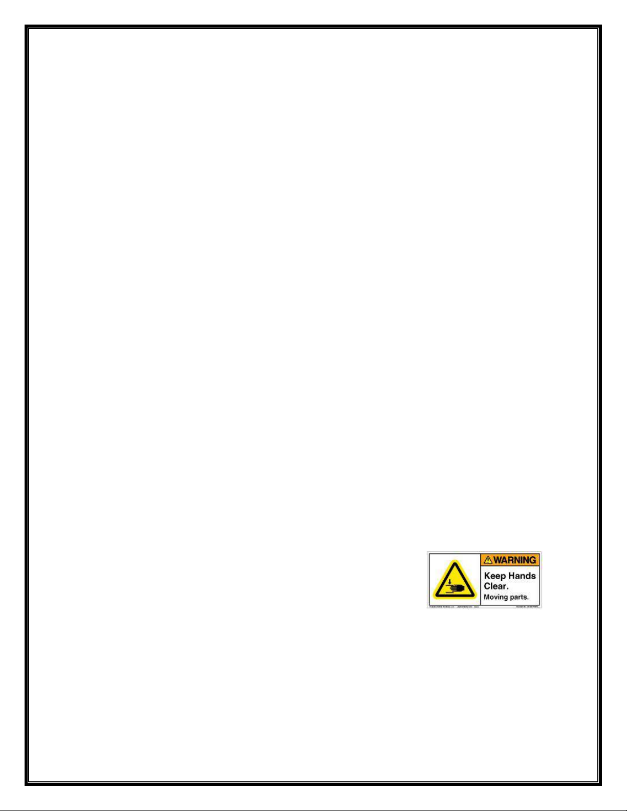
appropriate. Keep fingers and hands clear of lift arms during use.
WARNING: A SEAT BELT AND/OR STABILITY STRAP MUST BE ATTACHED TO THE SEAT AND
FULLY FASTENED AND USED DURING EACH TRANSFER.
PRODUCT OVERVIEW
The Stability Strap Assembly is designed to secure the User in a S.R.Smith Lift Seat. The unit is
constructed of high strength 4-Panel Nylon webbing and is UV and water resistant. It may be installed
with the integral 6” Hand Loop strap on either the left or right side of the seat. This instruction manual
describes installation for a right handed user to pull the strap free with their right hand. For left hand use,
simply switch the straps to the opposite sides of the Lift Seat.
700- 5600 Rev 6.16.2016
3
APPLICATION
For use with S.R.Smith lift products which are fitted with a 1-Piece Lift Seat. The straps mount to existing
mounting holes on rear side of the seatback.
STABILITY STRAP ASSEMBLY
The Stability Strap Assembly is comprised of two 2” wide Nylon webbed straps, a 27” long strap and a 32”
long strap. The 32” strap includes a 6” Hand Loop to allow the User to pull the two halve free of each
other after each use.
TOOLS REQUIRED
#2 Phillips Screwdriver
Tape Measure
INSTALLING THE STABILITY STRAP
1. Identify the (2) #10-24 brass inserts on the rear side of the seatback as shown below with the Left-
Right orientation noted:
Figure 1. Rear Side of the Seatback, showing mounting threads.
2. Compare the length of the two straps and select the shorter strap for installation first.
3. Orient the shorter 27” [0.68m] strap on the User’s left side (as sitting in seat) with the smooth side
of the Strap (where the grommet is located) against the seatback. The end of the 27” Strap with
the 9” length of Velcro™ should be facing away from the seatback and the grommet located over
the hole in the insert
U SER’S RI GH T SI D E
U SER’S LEFT SI D E
32” St rap at tachm ent27” St rap at tachm ent
Note that t his side has a 9” long
st rip of Velcro™ on t he side of t he
st rap away from t he seat back
Figure 2. View of 27”
strap orientation on
the seatback.
700- 5600 Rev 6.16.2016
4
4. Insert a #10-24 Screw through the #10 Flat Washer.
5. Insert the Screw through the ¼” hole in the Strap grommet and tighten with a #2 Phillips
screwdriver.
6. Orient the longer 32” [0.81m] strap over the User’s Right Side brass insert with the smooth side of
the webbing against the seatback. The side of this long strap with 9” of Velcro™ should be facing
toward the seatback.
7. Insert a #10-24 Screw through the #10 Flat Washer.
8. Insert screw through ¼” hole in the 32” Straps’ grommet and into the threads in brass insert.
9. Tighten with a #2 Phillips screwdriver.
10. If the User prefers, the straps may be swapped, allowing for the Hand Loop to be used by the
opposite hand.
11. Maintain the same orientation of the Velcro™ portions and follow previous instructions.
OPERATION
USING THE STABILITY STRAP
1. With the Stability Strap securely installed, the user takes their place in the seat.
2. Holding the short strap (without the Hand Loop), place it across the chest of the user.
3. Bring the other longer strap across and over the short strap, overlapping it, so as to engage the
Velcro™ portions of the straps snuggly.
4. Firmly press the two Velcro™ portions of the straps together.
5. To remove the strap after entering the water, the User or assistant may place their hand in the
Hand Loop of the strap and pull it away from the short strap.
CLEANING THE STABILITY STRAPS
1. To clean the Stability Straps, simply use a laundry detergent based cleanser with warm water as
you would with automotive seat belts.
2. Agitate the mix to a soapy consistency.
3. Remove the Straps from the Lift Seat and place them in the solution.
4. Allow the Straps to soak for several hours.
5. After soaking, use water and a soft brush to scrub the Straps.
6. Rinse with clean water.
7. For stubborn stains, apply a stain remover and scrub gently.
8. Rinse off the stain remover.
9. Allow the straps to dry.
Note: this side does n o t have
a 9” long strip of Velcro™
Figure 3. View of 32”
strap orientation on
the seatback
700- 5600 Rev 6.16.2016
5
LONG-TERM STORAGE
When storing the Stability Straps for an extended period of time keep the Stability Straps in a dry
temperature controlled area and out of the sun.
SPECIFICATIONS
STABILITY STRAP ASSEMBLY (Part Number: 900-6000)
1. Specifications
Dimensions:
Short Strap - 2” W (5.1 cm) x 27” L (68.5 cm)
Long Strap - 2” W (5.1 cm) x 32” L (81.3 cm)
Weight:
Stability Strap Assembly < 0.5 lbs. (< 1 kg) with Hardware.
PARTS LIST
Part Number Description Quantity
900-6000-1 Stability Strap Set 1
800-0305 Screw - #10-24 Pan Head X .5 L 2
800-0315 Washer - #10 Fender 2

This manual suits for next models

2

Other S.R.Smith Lifting System manuals

S.R.Smith PAL2 Series User manual

S.R.Smith

S.R.Smith PAL2 Series User manual

S.R.Smith aXs Series Guide

S.R.Smith

S.R.Smith aXs Series Guide

S.R.Smith PAL User manual

S.R.Smith

S.R.Smith PAL User manual

S.R.Smith MultiLift Guide

S.R.Smith

S.R.Smith MultiLift Guide

S.R.Smith Splash! 300-0000 Guide

S.R.Smith

S.R.Smith Splash! 300-0000 Guide

S.R.Smith aXs2 Guide

S.R.Smith

S.R.Smith aXs2 Guide

Popular Lifting System manuals by other brands

RGC HL7000 instructions

RGC

RGC HL7000 instructions

unicraft K 1001 operating instructions

unicraft

unicraft K 1001 operating instructions

CMC Boardlift CM70 SG instructions

CMC

CMC Boardlift CM70 SG instructions

Aqua Creek Products SPA LIFT ULTRA manual

Aqua Creek Products

Aqua Creek Products SPA LIFT ULTRA manual

GUIL TORO C Series user manual

GUIL

GUIL TORO C Series user manual

Zepro Z 1500-135 installation instructions

Zepro

Zepro Z 1500-135 installation instructions

EZ-ACCESS Modular Ramp Assembly manual

EZ-ACCESS

EZ-ACCESS Modular Ramp Assembly manual

Guldmann Stepless LP7 user manual

Guldmann

Guldmann Stepless LP7 user manual

Rev-A-Shelf RAS-ML Series installation instructions

Rev-A-Shelf

Rev-A-Shelf RAS-ML Series installation instructions

Schmalz VACUMASTER BASIC operating instructions

Schmalz

Schmalz VACUMASTER BASIC operating instructions

Rotary SM65-51 Operation and maintenance manual

Rotary

Rotary SM65-51 Operation and maintenance manual

Elebia NEO100 user manual

Elebia

Elebia NEO100 user manual

VMB TL-070 instructions

VMB

VMB TL-070 instructions

STARKE ARVID Inlift Instructions for use

STARKE ARVID

STARKE ARVID Inlift Instructions for use

RGC VL10K Guide On HD instructions

RGC

RGC VL10K Guide On HD instructions

WERTHER INTERNATIONAL 280AZ manual

WERTHER INTERNATIONAL

WERTHER INTERNATIONAL 280AZ manual

IDEAL MSC-6KLP Installation & operation manual

IDEAL

IDEAL MSC-6KLP Installation & operation manual

Pro-Lift T-5500 Operating instructions & parts manual

Pro-Lift

Pro-Lift T-5500 Operating instructions & parts manual

manuals.online logo
manuals.online logoBrands
  • About & Mission
  • Contact us
  • Privacy Policy
  • Terms and Conditions

Copyright 2025 Manuals.Online. All Rights Reserved.