S.R.Smith aXs Series Guide

700-3000 6.21.20161
aXs POOL LIFT
S.R. SMITH, LLC
CORPORATE HEADQUARTERS
P.O. Box 400 • 1017 S.W. Berg Parkway
Canby, Oregon 97013 USA
Phone (503) 266 2231 • Fax (503) 266 4334
OWNER’S MANUAL
&
MAINTENANCE PROCEDURES

700-3000 6.21.20162
DECK PROFILE SHEET CONFIRMATION
Aquatic access lifts are application specific. A completed Deck Profile Sheet helps to ensure the lift
purchased for the application will work in accordance to ADA guidelines. S.R. Smith reviews all submitted
Deck Profile Sheets as a service to our customers, free of charge. Before installing the pool lift, the
installer must review and confirm the information provided on the Deck Profile Sheet. If the description of
the application does not match the installation site, a new Deck Profile Sheet must be completed and
submitted to S.R. Smith.
NOTE: FAILURE TO COMPLETE AN ACCURATE DECK PROFILE SHEET MAY RESULT IN THE
LIFT NOT MEETING ADA COMPLIANCE GUIDELINES.
To complete the Deck Profile Sheet online, visit www.srsmith.com/liftprofile, contact Customer Service at
(800) 824-4387 or email sales@srsmith.com.

700-3000 6.21.20163
TABLE OF CONTENTS
aXs EU/K
DECK PROFILE SHEET CONFIRMATION........................................................................ 1
INTRODUCTION....................................................................................................... 4
WARNINGS AND SAFETY SUMMARY............................................................................ 5
PRODUCT OVERVIEW ............................................................................................... 5
aXs - PRODUCT COMPONENTS................................................................................... 6
UNPACKING & ASSEMBLY INSTRUCTIONS ................................................................. 11
USING THE aXs LIFT .............................................................................................. 12
TRANSFERRING..................................................................................................... 13
IN CASE OF BATTERY FAILURE........................................Error! Bookmark not defined.
STANDARD ACCESSORIES/OPTIONAL ACCESSORIES .................................................. 15
MAINTENANCE and CLEANSING ............................................................................... 16
TROUBLE SHOOTING.............................................................................................. 17
LONG-TERM STORAGE............................................................................................ 18
WARRANTY INFORMATION ...................................................................................... 18
SPECIFICATIONS ................................................................................................... 18
1. Dimensions/Capacity ........................................................................................................................... 19
2. Actuator ............................................................................................................................................... 19
3. Motor.................................................................................................................................................... 19
4. Battery ................................................................................................................................................. 19
5. Range of Motion Information ............................................................................................................... 19
6. Noise.................................................................................................................................................... 19
7. Materials and Finish Information ......................................................................................................... 19
PARTS LIST........................................................................................................... 20
Appendix - A ......................................................................................................... 21
Appendix - B ......................................................................................................... 22

700-3000 6.21.20164
READ THESE INSTRUCTIONS IN THEIR ENTIRETY BEFORE
BEGINNING INSTALLATION
INTRODUCTION
The purpose of this document is to provide information relating to the safe operation, care, and
maintenance of the aXs EU/K.
Intended Lift User:
All of S.R. Smith’s lifts have been designed to assist anyone who has problems entering or exiting a
swimming pool or spa - the only restriction is that the User does not exceed the weight limit of the product
(300 lb/136 kg to 400 lb/181 kg depending upon model). It is the responsibility of the lift Owner to ensure
that the correct safety procedures have been put in place and a risk assessment carried out. If a User is
mentally challenged or has severe physical disabilities these issues must be taken into account to
determine the number of persons required to complete the transfer onto the seat and the number of
persons required to be in the water, ready to receive the User. The correct seat belt must be attached to
the seat and fully fastened and used during each transfer.
Our goal is to provide our customers with the most advanced and innovative designs offering exceptional
quality at affordable prices. All of our lifts meet the specifications set forth by the Access Board - ADAAG
2004 (US only), Medical Device Directive, 93/42/EEC, RoHS2 Directive 2011/65/EU, EN 50581:2012
and ISO10535:2006 including repeating the lifting cycle of the hoist (lift) for a total of 11,000 cycles. The
lift system and AC powered battery charger complies with EN60601-1-2, 2007/03.
US Patent No. 5,790,995
aXs, the aXs logo and LiftOperator are registered trademarks of S.R. Smith, LLC.
Model / Product No.______
Product Name ___________
S.R. Smith, LLC
PO Box 400
1017 SW Berg Parkway
Canby, Oregon 97013 USA
Phone: 503-266-2231
Fax: 503-266-4334
www.srsmith.com
Made in USA
SN S
QNET BV
Kantstraat 19
NL-5076 NP Haaren
The Netherlands
qnet@ce-mark.com
qnet@ce-authorizedrepresentative.eu
24 VDC

700-3000 6.21.20165
WARNINGS AND SAFETY SUMMARY
DANGER – FAILURE TO FOLLOW THESE WARNINGS, INSTRUCTIONS AND THE OWNER’S MANUAL MAY
RESULT IN SEROUS INJURY OR DEATH
ADA GUIDELINE SUMMARY* (USA Only)
1009.2.1 Pool Lift Location
Pool lift shall be located where the water level does not exceed 48”. If entire pool water level exceeds
48”, place pool lift where convenient.
1009.2.2 Seat Location
In the raised position, the centerline of the seat shall be located over the deck a minimum of 16” from the
edge of the pool.
1009.2.3 Clear Deck Space
On the side of the seat opposite the water; a clear deck space shall be provided parallel with the seat.
The space shall be 36” wide minimum and shall extend forward 48” minimum from a line located 12”
behind the rear edge of the seat.
1009.2.4 Seat Height
The lift shall stop at 16” – 19” measured from the deck to the top of the seat surface when in the loading
position.
1009.2.8 Submerged Depth
The lift shall submerge the seat a minimum of 18” below the stationary water level.
*Compliance with ADA is the responsibility of the pool owner. Visit www.ada.gov for complete guidelines.
PRODUCT OVERVIEW

700-3000 6.21.20166
The aXs Aquatic Lift is a semi-portable lift system designed so that individuals with disabilities and
mobility impairments can have universal access to residential, hospitality and multiunit facility swimming
pools or spas. The aXs is powered by a 24 volt rechargeable battery. The lifting motion is provided by a
screw driven electronic actuator and an electronic gear motor provides the turning motion. S.R. Smith has
designed the safest possible lift system, following all instructions in the owner’s manual, and all product
labels is necessary to achieve safe, reliable and proper performance of the lift and avoid injury. This
design ensures consistent safe operation and minimizes service problems.
The aXs has a mast height of 36”/92 cm above the deck, provides 360º rotation and is intended to be
used with simple pool gutter configurations having a deck to water distance of no more than six inches.
Although the aXs must be operated from a stationary deck anchor it can be transported using the aXs
Caddy. The Caddy is designed to facilitate lifting the aXs out of the deck anchor and also serves as a
storage rack when the lift is not needed. The maximum lift capacity for aXs is 300 lb/136 kg. Only persons
healthy enough for water activities should use the aXs. Users should consult with their physician to
determine if water activities are appropriate for the User.
aXs - PRODUCT COMPONENTS
aXs 1000
COMPONENT DESCRIPTION
The lift is made up of several components:

700-3000 6.21.20167
Base Assembly - Mounts to the pool deck contains the turning elements of the lift.
Base Insert Stem - Slides into the anchor sleeve that is installed on the pool deck.
Mast - The main vertical component of the lift.
Actuator Arm - Primary lifting arm of the lift connects the mast to the seat arm and is raised by the
attached actuator.
Support Arm - Provides stability for the seat arm.
Seat Arm - Provides an attachment point for the seat assembly and nests inside the actuator arm to
avoid pinch points.
Housing - ABS plastic cover with an acrylic cap shields base assembly components from weather. When
cleaning the housing, be sure to use a clean, soft, non-abrasive material.
Actuator - Provides the up and down lifting action.
Rotation Motor Assembly – Consists of a mounting plate, 24-volt motor and small gear.
Control Box - The LiftOperator is available with an optional Activation Key feature that provides a higher
level of security by allowing control operation only with the use of the activation key. The unit controls all
lift operations identical to the user hand set. Three cables connect to the bottom of the Control Box to
enable operation of the lift. The largest connector is for the hand control. Connector # 1 is for the motor
cable (red stripe). Connector # 2 is for the actuator cable (green stripe).
Touchpad Control –
The touchpad control arrow keys can be used in the
event that the hand control is out of reach or fails.
Simply press and hold the arrow for the desired
action for one movement at a time – Up, Down, Left,
Right Releasing the Arrow stops movement.
Battery Level LED Indicators –
The Battery Level LED Indicators show battery
charge levels. The LED’s will illuminate when either
the touchpad control or the hand control is activated
and will stay lit for 10 seconds. At greater than 50%
the LED glows Green, at less than 50% the LED
glows Amber, and less than 25% the LED glows red
and indicates the battery requires charging. If the
less than 25% LED glows red, do not operate the lift.
Remove the battery and fully charge before use.
Service Required LED –
The Service Required LED will illuminate when the battery pack has been removed/replaced 120
times - approximately once every 4 months. This indicates that required maintenance for the lift
must be completed. Please see the maintenance section of the Lift Owner’s Manual for the
requirements. The Service Required LED can be reset by inserting a standard FAT-formatted
USB mass storage device (not included) into the USB Port on the bottom of the controller. When
CONNECTOR 1
(MOTOR CABLE)
CONNECTOR 2
(ACTUATOR CABLE)

700-3000 6.21.20168
the service light is illuminated the lift must not be used until required maintenance is
performed.
Emergency Stop Button –
In the event of an emergency, or if you need to stop lift movement immediately, pressing the
Emergency Stop Button (red button on the control) will stop all lift movement. At the same time an
audible alert will sound for 10 sec. then pause for 5 sec. and then the sequence will repeat until
the button is reset by turning it in the direction of the arrows on the button (clockwise). The
Emergency Alert LED will also flash Red when the button is pressed and will remain flashing until
the button is reset.
The Emergency Alert (audible and LED) can be activated by pressing any two buttons on the
hand control at the same time (provided with the lift). This will stop all lift movement and activate
the audible alert and the Red LED will flash. Once both buttons are released, the lift will return to
normal operation and the emergency audible alert will silence.
Activation Key –
The Optional Activation Key provides a higher level of security by
allowing control operation only with the use of the optional activation
key. To enable operation slide the Access Key into the slot next to the
touchpad control arrows. To disable operation remove the key. When
the key is inserted or removed the Battery Level LED will illuminate for
10 seconds.
USB Port –
The LiftOperator control contains a USB port that is used to download the performance log of the
lift. Using any standard FAT file formatted USB memory stick (widely available through retail
outlets) insert the stick into the slot on the bottom of the control on the far right hand side. Press
any of the touchpad control arrows; all three of the Battery Level LED’s will flash. During
downloading the Green greater than 50% Battery Level LED will flash. If the unit has a problem
downloading the performance log the Red less than 25% LED will flash. Remove the USB from
the port and re-insert it. If the Red 25% LED flashes again, confirm that the USB you are using is
FAT file formatted. The information from the USB can be downloaded to a PC for review and/or
copied to a spread sheet. The performance log will retain approximately 7,600 events. Once the
file is full it will remove the oldest event and replace with the newest.
After the summary data, the events are shown with the oldest first. The first column is the time in
seconds from that last event. The second column is the text describing the event. The third
column is duration of the activity noted in seconds.
An example of a short log file:
Activity Description
dev_id_upper,0 Programing data
dev_id_lower,1 Programing data
fw_rev,90 Firmware rev.
batt_volt_float,24929 Non-loaded battery voltage in millivolts
Activation Key (Option)

700-3000 6.21.20169
batt_volt_load,21487 Loaded battery voltage in millivolts
batt_capacity,99 Estimated battery capacity in %
charge_starts,8 Number of times charging was attempted
charge_completes,1 Number of times charging was finished successfully
0,power_on,1 Connecting Battery Pack
0,key_enable, Inserting Activation Key
2,alert_pressed, Emergency Button pressed
3,alert_released, Emergency Button released
8,lift_up,2 Lift movement - up
5,lift_down,2 Lift movement - down
11,lift_up,2
4,turn_left,2 Lift movement - turn left
3,turn_right,1 Lift movement - turn right
308,key_disable, Removing Activation Key
3,log_write, USB File Download
Battery Pack - The battery pack is located on top of the Control Box and is removable.
To remove - pull the battery pack away from the mounting
plate so that the latch on the battery pack clears the side tabs
on the mounting plate - then lift the battery pack up and away
from the Control Box.
To replace - align the battery pack with the mounting plate so
that the latch will drop over the center tab and that the bottom
of the battery pack will fit in the recessed area on top of the
Control Box. Lower the battery pack in place so that the latch
is fully captured by the mounting plate and the battery pack
drops fully seated onto the Control Box.
The battery must be completely removed from the lift and located away from the pool deck for
charging.
The battery pack should be charged daily. Do not allow battery to fully discharge, as it will shorten battery
life.

700-3000 6.21.201610
The battery pack has an LED indicator near the plug-in-port. It will glow Red when first plugged into the
transformer. If the LED remains Red this indicates the battery pack needs charging. When fully charged
the LED will glow Green. If the battery is fully charged and is plugged into the transformer the LED will
glow Red for approximately 10 sec. then glow Green. If the LED flashes Red when plugged in this
indicates a fault with the battery and indicates the battery pack should be replaced. All batteries are
inspected prior to shipment. See warranty policy regarding battery replacement for problems after sale.
Batteries have a normal lifespan of between 2-3 years, depending on use and care. A fully charged
battery will provide approximately 30 to 40-lifting cycles, depending on the weight of the users. Prior to
use the battery charge level should be checked by observing the LED indicator above the charger plug to
ensure sufficient charge level. The charger must be connected to the battery to view the LED.
It is not necessary to fully discharge the battery prior to charging. Battery should be charged daily and
cannot be overcharged. It takes up to twelve hours to fully charge depending upon battery usage. Do not
allow battery to fully discharge, as it will shorten battery life.
Do not drop the battery, as it could cause the unit to fail. If the battery case is cracked do not use and
replace the battery. During temperature extremes beyond the range of 41 F (5 C) to 104 F (40 C) remove
battery and place in a controlled environment or battery life may be shortened.
Battery Disposal - The batteries located inside the battery pack are recyclable and shall be disposed of
in accordance with applicable local, state/provincial or federal/national regulations.
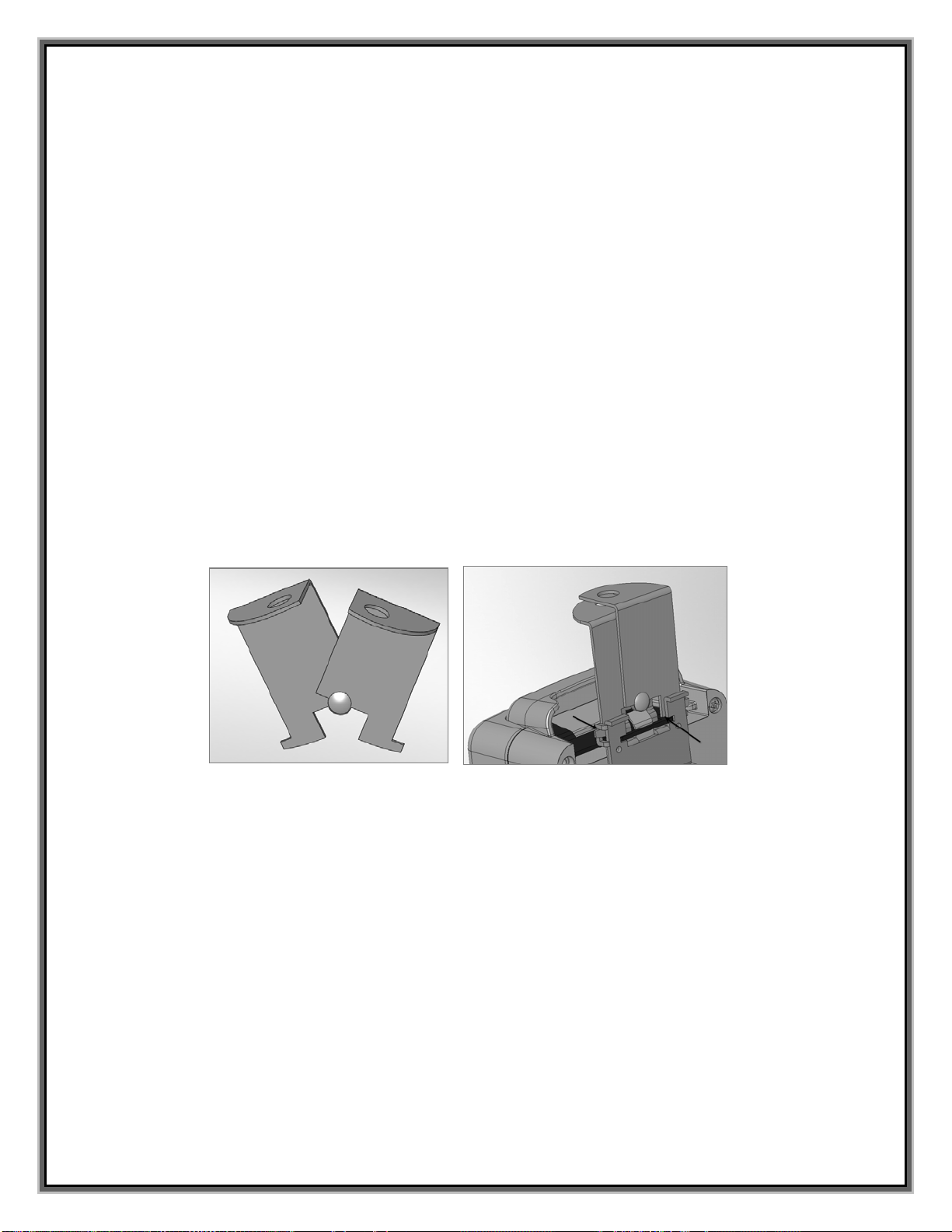
Locking Plate Assembly - The battery pack can be secured to the mounting plate using the provided
lock plate assembly. To install open the lock plate so that the bottom tabs are moved close to one another
to allow the lock plate to be inserted into the slots on the mounting plate secured to the lift. Close the lock
plate assembly so that the tabs are captured by the slots. Insert a padlock (not provided) through the
holes on the lock plate assembly to secure it.
Hand Control - The four button unit controls all lift movements. The arrows indicate direction of
movement. Control is fully waterproof and meets IP67 standards.
Seating System - The seat is manufactured from roto-molded plastic with a stainless steel
frame.
The seat belt must be used during each use. The footrest is removable and will float upwards to
prevent damage if the seat is lowered too far. It is recommended that the seat be rinsed off with
fresh water between each use and cleansed daily with a disinfectant solution of 1:100 dilution of
household bleach to fresh water and then rinsed with fresh water. In the event of a
contamination incident such as patient/user excreta - cleanse seat and seatbelt immediately with the
above disinfectant solution. Do not use seat or seatbelt if it is damaged or becomes worn out.
The optional armrests (US only - standard on export models) are designed for support when transferring
onto the seat. They can be rotated up out of the way during transfer. If the lift did not include the optional
arm rests (US only) they can be purchased separately and easily installed at a later date.

700-3000 6.21.201611
This lift seat assembly is designed to be used exclusively with S.R. Smith aquatic access lifts.
UNPACKING & ASSEMBLY INSTRUCTIONS
REFER TO THE DIAGRAM (page 6) FOR PARTS IDENTIFICATION.
READ THESE INSTRUCTIONS IN THEIR ENTIRETY BEFORE BEGINNING INSTALLATION
Prior to opening the shipping pallet, carefully inspect the external condition of the shipping
materials for any visible damage. It is important that any damage be noted on the Bill of Lading
prior to signing for the delivery. Contact either S.R. Smith or your dealer immediately to notify us
of any damage or missing parts.
Ensure mounting anchor has been installed in the correct location in the pool deck for proper lift
operation. It is recommended that the anchor be installed by a person familiar with installing pool
deck equipment.
The aXs is shipped on a covered pallet and is mostly assembled; no tools are required for installation and
setup. Position pallet close to deck anchor for easier assembly and set up.
Unpacking & Assembly Procedure for the aXs:
1. Carefully remove plastic covering from pallet.
2. Carefully remove any wood bracing from pallet.
3. Remove seat assembly and set aside for attachment.
4. Remove lift from pallet and place into deck anchor.
5. Remove and unwrap hand control from accessory carton. Insert plug into large connector on the
Control Box and hang hand control on handle. Make sure plug is secure.
6. Ensure pre-installed plugs are secure in sockets marked 1 and 2
7. Attach battery to Control Box. To remove battery pull slightly away from mounting plate and lift
battery pack off of the Control Box.
8. Cover Control Box and battery with Console/Battery Cover to protect from moisture.
9. Check up and down controls for proper operation - both touch pad and hand controls.
10. Check side to side controls for proper operation – both touch pad and hand controls (4 Button
Control only).
11. Check Emergency Stop button for operation/activation of internal sounder.
12. For Controls with the optional Activation Key – Key must be inserted into slot for operation. When
Key is removed lift with not operate. (Note – Emergency Stop button and alert will operate without
Key inserted into slot)
13. Attach battery to Control Box.
14. Rotate lift so that the seat arm is positioned over the pool deck.

700-3000 6.21.201612
15. Attach seat assembly with bolt and thumbnut in appropriate hole. For storage, seat can be
attached facing inward for less space.
16. Attach foot rest to seat with bolts and thumbnuts.
USING THE aXs LIFT
Obey all User Instructions listed in the Owner’s Manual whenever using lift. Obey all Caution,
Warning, Operating Instruction(s) and Labels located on the lift whenever using. It is the
responsibility of the lift Owner to ensure that the correct safety procedures have been put in place
and a risk assessment carried out. If a User is mentally challenged or has severe physical
disabilities these issues must be taken into account to determine the number of persons required
to complete the transfer onto the seat and the number of persons required to be in the water,
ready to receive the User. If the aXs will be used by a disabled person living on their own, a
communication device should be installed in the area of use to call for assistance in the event of
an emergency. Only persons healthy enough for water activities should use the aXs. Users should
consult with their physician to determine if water activities are appropriate for the User. Keep
fingers and hands clear of lift arms during use.

700-3000 6.21.201613
aXs Transferring Diagram
TRANSFERRING
Once the unit is positioned for use, use the following procedure to transfer to the seat and into the water.
Only persons healthy enough for water activities should use the aXs. Users should consult with their
physician to determine if water activities are appropriate for the User:
Rotate the seat to either side of lift for best transfer position.
Raise or lower the seat to proper transfer height.
Transfer onto the seat, ensuring that the user’s weight is centered on seat. Armrests can be
rotated up if necessary. If user has a wheelchair, keep the wheelchair close by for easy retrieval.
Fasten Seat Belt - thread loose end of belt strap through buckle - pull tight - to close - press latch
down on belt material.
Raise seat to allow enough leg room for rotation.
Rotate seat to the 12:00 position, over the water.
Lower the seat into the pool. The waterproof hand control can remain connected to seat if
swimmer is operating lift.
Unfasten Seat Belt - grasp latch and lift up, pull loose end from latch.
When finished, return to the seat, ensuring user’s weight is centered on seat.
Fasten Seat Belt.
Raise seat to allow enough leg room for rotation.
Rotate seat to original transfer position.
Raise or lower seat to proper transfer height.
Unfasten Seat Belt.
Transfer off of the seat.

700-3000 6.21.201614
IN CASE OF HAND CONTROL FAILURE
Lifting failure - In the event of a lifting failure, there are control buttons built into the control box. Press
the appropriate up or down/left or right button located on the front panel of the control box.
If the aXs will be used by a disabled person living on their own, a communication device should
be installed in the area of use to call for assistance in the event of an emergency.
POOL DECK INSTALLATION FOR THE aXs ANCHOR
Ensure Locking Anchor has been installed in the correct location in the pool deck for proper lift
operation. It is recommended that the anchor be installed by a person familiar with installing pool
deck equipment.
The optimal mounting distance for the deck anchor is between 12”/30.5 cm to 18”/46cm from the edge of
the pool. The aXs is designed to be used with simple pool edge designs without protruding gutters.
Please call S.R.Smith with any questions concerning deck anchor placement or if the aXs will work in
your installation.
Installing a Locking Anchor in a Concrete Deck
The proper installation of the anchor depends on the construction and condition of the deck. If the deck
meets the thickness and re-enforcing requirements shown in Appendix A then the anchor can be installed
according to the instructions outlined in Appendix A.
If the existing deck does not meet the requirements outlined in Appendix A then the anchor can be
installed per the instructions in Appendix B or you can consult with an engineering professional.
The deck anchor reaction loads can be found in the Specification Section of this manual.
Once installed, you can lock the aXs into place by removing the back housing of the base and use the
provided hardware with a 9/16 socket wrench to tighten it into place.
Properly bond the anchor socket using the attached bonding screw per local codes.
Locking Deck Anchor
(Install the anchor so the locking tab is either parallel to the Deck to Water (DW) edge
or perpendicular and furthest away from the DW edge)
DW EDGE
or

700-3000 6.21.201615
Turning failure - If the lift will not turn electronically, remove the housing cover and locate the toggle
clamp (red handle). Pull upward on the handle and rotate until the handle is horizontal. With the handle in
the horizontal position, pull on the handle to rotate the assembly in the clockwise direction. This will
disengage the gears and allow the lift to be turned manually. Follow the proceeding process in reverse to
reengage the gear assembly.
If the aXs will be used by a disabled person living on their own, a communication device should
be installed in the area of use to call for assistance in the event of an emergency.
STANDARD ACCESSORIES/OPTIONAL ACCESSORIES
The following items are included with all pool lift models:
Seat Belt Assembly - Nylon water-resistant belt for added security.
Battery/Charger – 24-volt rechargeable battery.
TOGGLE CLAMP
HANDLE
LIFT HANDLE
AND ROTATE
PULL HANDLE TO
DISENGAGE GEARS

700-3000 6.21.201616
Optional accessories may be purchased for your aXs lift through your Authorized Reseller. The following
accessories are available:
Console/Battery Cover – P/N 910-1000: Protects battery and control unit from exposure to moisture
Total Cover - P/N AX9005: Made of weather resistant nylon material to keep unit protected from
elements when not in use.
Spine Board Attachment - P/N 500-1000: Can be used to convert lift for use with any standard spine
board. (Spine Board not included)
Anchor & Cap – P/N 300-6200L - Lift Lock deck anchor measures 2.875”/ 7.30 cm OD, 2.75” / 6.98 cm
ID. Includes cap and bonding screw.
MAINTENANCE and CLEANSING
Minimal maintenance will prolong the life of your lift. Keep all electronic components clean and dry.
Excessive moisture collection can affect battery and lift performance and could lead to battery failure
and/or the lift failing to operate. If the lift is used outdoors, an optional full cover is available and
recommended.
Owners of lifts should be aware of any applicable local, state/provincial or federal/national regulations
regarding the inspection and or testing of lifts.
The following schedule shall be performed to insure proper operation with the Daily items
performed before each use:
Maintenance Performed Daily Weekly Monthly
Check battery level before each use / Charge battery daily
Wipe Control Box and battery connection with a clean dry rag
Examine lift for any damage, lose or missing hardware
Test for normal operation
Spray gear assembly with a heavy-duty rust inhibitor/lubricant
such as LPS 3 - Heavy-Duty Inhibitor
Make sure all cable connections are properly secured
Inspect lift frame, mast, support arm and seat assembly for rust
Cleansing Performed – after each use
Rinse seat and seatbelt with fresh water between each use -
Cleanse seat and seatbelt with a disinfectant solution of 1:100
dilution of household bleach to fresh water and then rinse with
fresh water and dry entire lift daily. In the event of a
contamination incident such patient/user excreta - cleanse seat
and seatbelt immediately with the disinfectant solution*
Cleanse all battery connections with a nylon scouring pad
Cleanse all metallic surfaces with a cleaner wax to maintain the
finish of the lift
* When using the disinfection solution avoid direct contact with the skin and eyes. In the event of
a contamination incident - immerse the seat belt or in the disinfection solution for 10 min. and
then rinse thoroughly with fresh water.

700-3000 6.21.201617
TROUBLE SHOOTING
Be sure the battery is fully charged before troubleshooting.
Lift does not rotate
Does lift raise or lower?
Yes.
1. Check connection to Control Box. Be sure plug is pushed in all the way.
2. Check hand control connection to Control Box for damaged pins.
3. Check connections on terminal block located on frame for loose wires.
4. Check connection cable for damage.
5. Try operating the lift using the control buttons on the front panel of the controller. If the
lift rotates when using the buttons on the control box, the hand control is likely the
problem.
6. If the lift does not rotate when using the buttons on the control box, reverse the motor
cables as follows: Locate the area on the Control Box where the cables are attached.
Swap the actuator cable from connector #2 with the 24v motor cable from connector #1.
Activate the up and down buttons on the hand control. If lift rotates, the problem is likely
the hand control. If lift does not rotate, the problem is likely the 24v motor.
7. Contact your Authorized Reseller or S.R. Smith for replacement information.
Does lift raise or lower?
No.
1. Check battery charge level.
2. Check battery connection.
3. Use another fully charged battery. If lift continues to not function, replace the Control
Box.
Lift does not Raise or Lower
Does lift rotate?
Yes.
1. Check connection to Control Box. Be sure plug is pushed in all the way.
2. Check hand control connection to Control Box for damaged pins.
3. Check connection cable for damage.
4. Activate the up and down buttons on the front panel of the control box. If lift raises
and lowers, the problem is likely the hand control.
5. If the lift does not raise and lower when using the buttons on the control box, reverse
the cables as follows: Locate the area on the Control Box where the cables are
attached. Swap the actuator cable from the connector #2 and the 24v motor cable
from connector #1. Activate the left and right buttons on the hand control. If the lift
raises and lowers, the problem is likely the hand control. If the lift does not raise and
lower, the problem is likely the Actuator.
6. Contact your Authorized Reseller or S.R. Smith for component replacement
information.
Does lift rotate?
No.
1. Check battery charge level.
2. Check battery connection.
3. Use another fully charged battery. If lift does not function, replace the Control Box.

700-3000 6.21.201618
LONG-TERM STORAGE
When storing the lift for an extended period of time:
Wash seat with disinfectant solution and then rinse with fresh water and dry entire lift
Spray gear assembly with a heavy duty rust inhibitor and lubricant such as LPS 3 - Heavy-Duty
Inhibitor
Keep the battery on the charger in a dry temperature controlled area
Cover unit and store in a dry location away from pool chemicals
information regarding Authorized Resellers worldwide visit www.srsmith.com
WARRANTY INFORMATION
The S.R. Smith warranty becomes effective on the date of manufacture.
To initiate a warranty replacement, Please follow the process outlined below.
1. Take photos of the damaged product.
a) The photo must include the entire unit
b) Also include one photo or more of the damaged area.
2. Write down or take a photo of the serial # sticker from the product.
S.R. Smith provides a serial # for every pool lift we produce. The sticker with the serial number
can be found at the bottom of the mast near the base.
3. Attach the photos and the serial # to a written request for replacement under the S.R.
Smith warranty. Please include the following information:
a) Product name and description.
b) Date of purchase and/or date of installation.
c) Description of damage.
d) Shipping address with a contact name and phone number.
4. Send photos, serial # sticker and your written request by email or mail to
S.R. Smith, LLC
PO Box 400
1017 SW Berg Pkwy
Canby, OR 97013
Attn: Warranty Specialist
**NOTE: Missing information will result in a processing delay and possibly denial of your claim.
Should you have any questions regarding this process, please contact
S.R. Smith's Warranty specialist at 800.824.4387 or 503.266.2231 or email warranty@srsmith.com
SPECIFICATIONS
aXs EU/K

700-3000 6.21.201619
1. Dimensions/Capacity
Mast Height 32”/81 cm
Height-Arm Raised 56.5”/143.5 cm
Seat Width 23”/58.5cm
Overall Length-extended 68.75”/174.6 cm
Storage Length-w/o chair 47”/19 cm
Unit Weight-inc. chair 81 lb/36.7 kg
Unit Weight-w/o chair 68 lb/30.8 kg
Power 24v DC
Battery Life 30 cycles (approx.)
Lifting Capacity 300 lb/136 kg
Anchor Reaction Load
Vertical 380 lb/172 kg
Torque 1400 ft lb/1898 NM
2. Actuator
Type Screw Type Mechanical Actuator
Maximum Thrust 1680 lb/7472N
Voltage 24v DC
Maximum Amp Draw 9
Maximum Speed 0.59 inch/sec./1.49cm/sec.
3. Motor
Rotation 24 VDC, 13 RPM
Gearing Ratio 9:1
4. Battery
Power 24 VDC, IP65 Gel Lead Acid
Temperature Range 41 F (5 C) to 104 F (40 C)
5. Range of Motion Information
Vertical Travel 46”/117 cm
Rotation Continuous
Widest Arc-inc. chair 61”/155 cm
Narrowest Arc-inc. chair 51”/129.5 cm
6. Noise
Noise level below 50 dB (A), measured according
to DS/EN ISO 3746”
7. Materials and Finish Information
Frame Powder Coated Stainless Steel
Housing Vacuum Formed ABS Plastic
Arms Powder Coated Aluminum
Mast Powder Coated Stainless Steel
Seat Assembly Seat: Rotomolded Plastic
Frame: Powder Coated Stainless Steel
Covers Urethane coated nylon

700-3000 6.21.201620
PARTS LIST
Item # Part # Description
1 AX5001 LA34 Actuator
2 1001499 4 Button Control
3 1001555 4 Button Control w/Activation Key (not shown)
4 1001495 Battery Pack
5 1001530 Battery Charger (not shown)
6 100-4000A Hand Control
7 AX1430 Hand Control Hanger
8 120-1100 24v Motor
9 120-1800 Motor Cord w/ O ring (not shown)
10 100-3100 Battery Bracket
11 AX2000 Mast
12 AX2100 Actuator Arm Assembly
13 AX2200 Support Arm Assembly
14 AX2300 Seat Arm
15 160-8000A Seat Assembly
16 AX3000 Large Gear
17 800-5065 Small Gear
18 800-5066 Toggle Clamp
19 AX4000 aXs Housing Back
20 AX4050 aXs Housing Front
21 AX9004* aXs Battery Console Cover (Green) (not shown)
22 AX9003 aXs Seat Belt Assembly (Gray)
23 AX8360 Long Bushings
24 AX8340 Short Bushings
25 AX8000 Sidewalk Bolt
26 AX8400 Threaded Shaft-Long
27 AX8500 Threaded Shaft-Short
28 AX8800 Speed Nut
29 300-6200*L Locking Deck Anchor (not shown)
30 AX3600 Hub/Spindle Assembly
31 170-3000A Arm Rest Assembly (Pair)
32 160-2300A Footrest Gray
33 AX9005 aXs Total Cover (Optional Accessory, Not Shown)
34 500-1000 Spine Board Attachment (Optional Accessory, Not Shown)
35 900-6000 Stability Strap (Optional Accessory, Not Shown)
36 970-5000 Seat Cover (Optional Accessory, Not Shown)
This manual suits for next models
1
Table of contents
Other S.R.Smith Lifting System manuals